


193-DNENCATR
Table of contents
 Loading...
User Manual
Bulletin 193 EtherNet/IP Communications Auxiliary
Catalog Number
193-DNENCAT, 193-DNENCATR
Important User Information
Solid-state equipment has operational characteristics differing from those of electromechanical equipment. Safety
Guidelines for the Application, Installation and Maintenance of Solid State Controls (publication SGI-1.1
available from
your local Rockwell Automation sales office or online at http://www.rockwellautomation.com/literature/
) describes some
important differences between solid-state equipment and hard-wired electromechanical devices. Because of this difference,
and also because of the wide variety of uses for solid-state equipment, all persons responsible for applying this equipment
must satisfy themselves that each intended application of this equipment is acceptable.
In no event will Rockwell Automation, Inc. be responsible or liable for indirect or consequential damages resulting from
the use or application of this equipment.
The examples and diagrams in this manual are included solely for illustrative purposes. Because of the many variables and
requirements associated with any particular installation, Rockwell Automation, Inc. cannot assume responsibility or
liability for actual use based on the examples and diagrams.
No patent liability is assumed by Rockwell Automation, Inc. with respect to use of information, circuits, equipment, or
software described in this manual.
Reproduction of the contents of this manual, in whole or in part, without written permission of Rockwell Automation,
Inc., is prohibited.
Throughout this manual, when necessary, we use notes to make you aware of safety considerations.
Allen-Bradley, Rockwell Software, Rockwell Automation, and TechConnect are trademarks of Rockwell Automation, Inc.
Trademarks not belonging to Rockwell Automation are property of their respective companies.
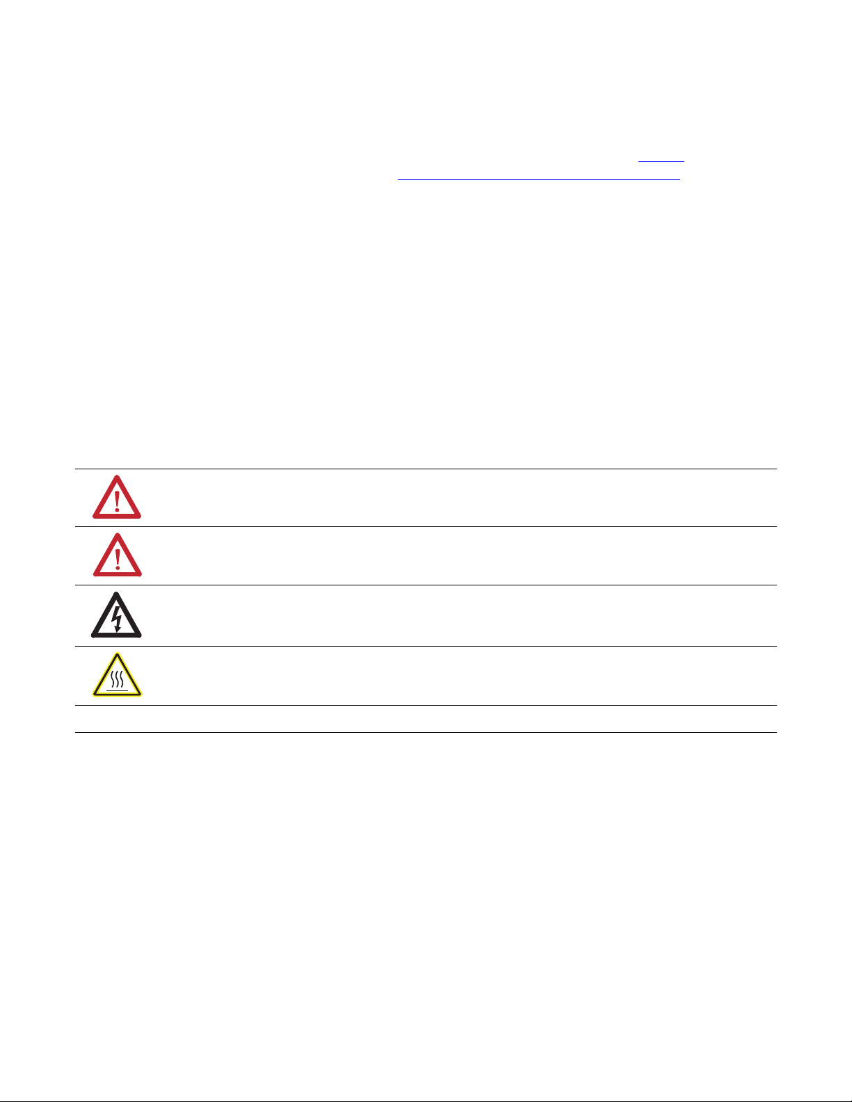
WARNING: Identifies information about practices or circumstances that can cause an explosion in a hazardous
environment, which may lead to personal injury or death, property damage, or economic loss.
ATTENTION: Identifies information about practices or circumstances that can lead to personal injury or death,
property damage, or economic loss. Attentions help you identify a hazard, avoid a hazard, and recognize the
consequence
SHOCK HAZARD: Labels may be on or inside the equipment, for example, a drive or motor, to alert people that
dangerous voltage may be present.
BURN HAZARD: Labels may be on or inside the equipment, for example, a drive or motor, to alert people that
surfaces may reach dangerous temperatures.
IMPORTANT
Identifies information that is critical for successful application and understanding of the product.

3 Rockwell Automation Publication 193-UM014B-EN-P - December 2011
Chapter 1
Installation & Wiring
Introduction . . . . . . . . . . . . . . . . . . . . . . . . . . . . . . . . . . . . . . . . . . . . . . . . . . . . . . 7
Overview . . . . . . . . . . . . . . . . . . . . . . . . . . . . . . . . . . . . . . . . . . . . . . . . . . . . . . . . . 7
Features . . . . . . . . . . . . . . . . . . . . . . . . . . . . . . . . . . . . . . . . . . . . . . . . . . . . . . . . . . 9
Installation . . . . . . . . . . . . . . . . . . . . . . . . . . . . . . . . . . . . . . . . . . . . . . . . . . . . . . . 9
Wiring . . . . . . . . . . . . . . . . . . . . . . . . . . . . . . . . . . . . . . . . . . . . . . . . . . . . . . . . . . 10
Dimensions . . . . . . . . . . . . . . . . . . . . . . . . . . . . . . . . . . . . . . . . . . . . . . . . . . . . . . 11
Network Design. . . . . . . . . . . . . . . . . . . . . . . . . . . . . . . . . . . . . . . . . . . . . . . . . . 12
Chapter 2
Configure the EtherNet/IP
Communications Auxiliary
Introduction . . . . . . . . . . . . . . . . . . . . . . . . . . . . . . . . . . . . . . . . . . . . . . . . . . . . . 15
Determining Network Parameters . . . . . . . . . . . . . . . . . . . . . . . . . . . . . . . . . 15
Setting the IP Network Address . . . . . . . . . . . . . . . . . . . . . . . . . . . . . . . . . . . 16
EtherNet/IP Node Address Selection Switches. . . . . . . . . . . . . . . . . . 16
Assign Network Parameters via the BOOTP/DHCP Utility. . . . . . . . . 17
Assign Network Parameters Via a Web Browser & MAC Scanner
Software . . . . . . . . . . . . . . . . . . . . . . . . . . . . . . . . . . . . . . . . . . . . . . . . . . . . . . . . . 19
Other Factors to Consider When Assigning Network Parameters. 22
Duplicate IP Address Detection . . . . . . . . . . . . . . . . . . . . . . . . . . . . . . . . . . . 22
Behavior of Modules With Duplicate IP Addresses . . . . . . . . . . . . . . 23
DNS Addressing . . . . . . . . . . . . . . . . . . . . . . . . . . . . . . . . . . . . . . . . . . . . . . . . . 23
Electronic Data Sheet (EDS) File Installation . . . . . . . . . . . . . . . . . . . . . . . 23
Download the EDS File . . . . . . . . . . . . . . . . . . . . . . . . . . . . . . . . . . . . . . . 24
Register the EDS File . . . . . . . . . . . . . . . . . . . . . . . . . . . . . . . . . . . . . . . . . 25
Chapter 3
Configure the DeviceNet
Network
Introduction . . . . . . . . . . . . . . . . . . . . . . . . . . . . . . . . . . . . . . . . . . . . . . . . . . . . . 31
Configuration. . . . . . . . . . . . . . . . . . . . . . . . . . . . . . . . . . . . . . . . . . . . . . . . . . . . 31
Chapter 4
Add Devices to the DeviceNet
Network
Introduction . . . . . . . . . . . . . . . . . . . . . . . . . . . . . . . . . . . . . . . . . . . . . . . . . . . . . 35
DeviceNet Node Addressing . . . . . . . . . . . . . . . . . . . . . . . . . . . . . . . . . . . . . . 35
Node Address Basics . . . . . . . . . . . . . . . . . . . . . . . . . . . . . . . . . . . . . . . . . . 36
Set the Node Address . . . . . . . . . . . . . . . . . . . . . . . . . . . . . . . . . . . . . . . . . . . . . 36
Using the Hardware Mechanism. . . . . . . . . . . . . . . . . . . . . . . . . . . . . . . 36
Using the DeviceNet Node Commissioning Tool . . . . . . . . . . . . . . . 37
Add DeviceNet Modules to the Scan List. . . . . . . . . . . . . . . . . . . . . . . . . . . 40
Simple . . . . . . . . . . . . . . . . . . . . . . . . . . . . . . . . . . . . . . . . . . . . . . . . . . . . . . . 40
User-Defined. . . . . . . . . . . . . . . . . . . . . . . . . . . . . . . . . . . . . . . . . . . . . . . . . 41

4 Rockwell Automation Publication 193-UM014B-EN-P - July 2011
Chapter 5
View & Configure Parameters
Introduction . . . . . . . . . . . . . . . . . . . . . . . . . . . . . . . . . . . . . . . . . . . . . . . . . . . . . 43
View & Edit . . . . . . . . . . . . . . . . . . . . . . . . . . . . . . . . . . . . . . . . . . . . . . . . . . . . . 43
Chapter 6
Automatic Device Recovery or
Replace
Introduction . . . . . . . . . . . . . . . . . . . . . . . . . . . . . . . . . . . . . . . . . . . . . . . . . . . . . 47
Setting ADR . . . . . . . . . . . . . . . . . . . . . . . . . . . . . . . . . . . . . . . . . . . . . . . . . . . . . 47
Chapter 7
Automation Controller
Communications
Introduction . . . . . . . . . . . . . . . . . . . . . . . . . . . . . . . . . . . . . . . . . . . . . . . . . . . . . 51
Ethernet Messaging. . . . . . . . . . . . . . . . . . . . . . . . . . . . . . . . . . . . . . . . . . . . . . . 51
I/O Messaging . . . . . . . . . . . . . . . . . . . . . . . . . . . . . . . . . . . . . . . . . . . . . . . . . . . 51
ControlLogix Configuration with Add-On Profiles . . . . . . . . . . . . . 51
EtherNet/IP Network Configuration with Add-On Profiles . . . . . 53
Accessing Module Data with Add-On Profiles . . . . . . . . . . . . . . . . . . 56
ControlLogix Generic Configuration . . . . . . . . . . . . . . . . . . . . . . . . . . 57
EtherNet/IP Generic Module Configuration . . . . . . . . . . . . . . . . . . . 58
Accessing Generic Module Data . . . . . . . . . . . . . . . . . . . . . . . . . . . . . . . 61
Logic Explicit Messaging . . . . . . . . . . . . . . . . . . . . . . . . . . . . . . . . . . . . . . . . . . 63
Chapter 8
E-mail/Text
Introduction . . . . . . . . . . . . . . . . . . . . . . . . . . . . . . . . . . . . . . . . . . . . . . . . . . . . . 67
E-mail Notifications . . . . . . . . . . . . . . . . . . . . . . . . . . . . . . . . . . . . . . . . . . . . . . 67
Events . . . . . . . . . . . . . . . . . . . . . . . . . . . . . . . . . . . . . . . . . . . . . . . . . . . . . . . 67
E-mail Contents . . . . . . . . . . . . . . . . . . . . . . . . . . . . . . . . . . . . . . . . . . . . . . 67
E-mail Configuration . . . . . . . . . . . . . . . . . . . . . . . . . . . . . . . . . . . . . . . . . 68
Configure Device Identity. . . . . . . . . . . . . . . . . . . . . . . . . . . . . . . . . . . . . 69
Text Notifications . . . . . . . . . . . . . . . . . . . . . . . . . . . . . . . . . . . . . . . . . . . . 70
Limitations . . . . . . . . . . . . . . . . . . . . . . . . . . . . . . . . . . . . . . . . . . . . . . . . . . . . . . 71
Chapter 9
Device Parameters
Introduction . . . . . . . . . . . . . . . . . . . . . . . . . . . . . . . . . . . . . . . . . . . . . . . . . . . . . 73
Parameter Programming . . . . . . . . . . . . . . . . . . . . . . . . . . . . . . . . . . . . . . . . . . 73
Parameter Listing. . . . . . . . . . . . . . . . . . . . . . . . . . . . . . . . . . . . . . . . . . . . . 73

Rockwell Automation Publication 193-UM014B-EN-P - July 2011 5
Chapter 10
Troubleshooting
Introduction . . . . . . . . . . . . . . . . . . . . . . . . . . . . . . . . . . . . . . . . . . . . . . . . . . . . . 79
EtherNet/IP Modules of Operation. . . . . . . . . . . . . . . . . . . . . . . . . . . . . . . . 79
Power-Up Reset Mode . . . . . . . . . . . . . . . . . . . . . . . . . . . . . . . . . . . . . . . . 80
Run Mode . . . . . . . . . . . . . . . . . . . . . . . . . . . . . . . . . . . . . . . . . . . . . . . . . . . 81
Recoverable Error Mode . . . . . . . . . . . . . . . . . . . . . . . . . . . . . . . . . . . . . . 82
Unrecoverable Error Mode . . . . . . . . . . . . . . . . . . . . . . . . . . . . . . . . . . . . 82
Troubleshooting Procedures . . . . . . . . . . . . . . . . . . . . . . . . . . . . . . . . . . . . . . 82
. . . . . . . . . . . . . . . . . . . . . . . . . . . . . . . . . . . . . . . . . . . . . . . . . . . . . . . . . . . . . 84
Appendix A
Specifications
Specifications . . . . . . . . . . . . . . . . . . . . . . . . . . . . . . . . . . . . . . . . . . . . . . . . . . . . 85
Appendix B
EtherNet/IP & DeviceNet
Information
Electronic Data Sheet (EDS) Files . . . . . . . . . . . . . . . . . . . . . . . . . . . . . . . . . 89
Common Industrial Protocol (CIP) Objects. . . . . . . . . . . . . . . . . . . . . . . . 89
Identity Object — CLASS CODE 0x01. . . . . . . . . . . . . . . . . . . . . . . . 89
Message Router Object — CLASS CODE 0x02. . . . . . . . . . . . . . . . . 90
DeviceNet Object — CLASS CODE 0x03 . . . . . . . . . . . . . . . . . . . . . 91
Assembly Object — CLASS CODE 0x04 . . . . . . . . . . . . . . . . . . . . . . 91
Connection Manager Object — CLASS CODE 0x06 . . . . . . . . . . . 95
Parameter Object — CLASS CODE 0x0F. . . . . . . . . . . . . . . . . . . . . . 96
Device Level Ring (DLR) Object — CLASS CODE 0x47 . . . . . . . 97
QoS Object — CLASS CODE 0x48 . . . . . . . . . . . . . . . . . . . . . . . . . . . 98
Non-Volatile Storage Object — CLASS CODE 0xA1 . . . . . . . . . . . 98
Port Object — CLASS CODE 0x0F4 . . . . . . . . . . . . . . . . . . . . . . . . . . 99
TCP/IP Interface Object — CLASS CODE 0xF5 . . . . . . . . . . . . . 100
Ethernet Link Object — CLASS CODE 0xF6 . . . . . . . . . . . . . . . . . 101

6 Rockwell Automation Publication 193-UM014B-EN-P - July 2011
Rockwell Automation Publication 193-UM014B-EN-P December 2011 7
Chapter
1
Installation & Wiring
Introduction
The purpose of this chapter is to provide the necessary instructions to successfully
install the Bulletin 193 Ethernet™/IP Communications Auxiliary and properly
connect it to an EtherNet/IP and DeviceNet™ network.
Overview
The Bulletin 193 EtherNet/IP Communications Auxiliary is an EtherNet/IP to
DeviceNet linking device. It provides a means for devices that primarily
communicate on a DeviceNet network (e.g., a Bulletin 193 or 592 E3 Plus
Overload Relay or a Bulletin 825-P Electronic Overload Relay) to communicate
to EtherNet/IP-based scanners. The EtherNet/IP Communications Auxiliary
allows up to six (6) DeviceNet-based devices to be scanned via Implicit Messaging
and can bridge explicit messaging for all nodes on a DeviceNet network. The
EtherNet/IP Communications Auxiliary uses an internal web server to configure
the module, the DeviceNet network, and DeviceNet-based devices that fully
support the Parameter Object.
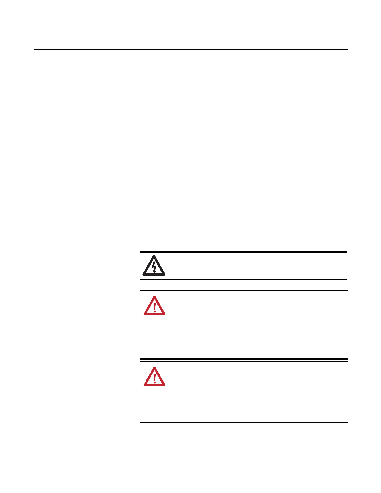
SHOCK HAZARD: To prevent electrical shock, disconnect the EtherNet/
IP Communications Auxiliary from its power source before installing or
servicing. Install in suitable enclosure. Keep free from contaminants.
ATTENTION: The EtherNet/IP Communications Auxiliary contains ESD
(electrostatic discharge) sensitive parts and assemblies. Static control
precautions are required when installing, testing, servicing, or repairing
the EtherNet/IP Commuications Auxiliary. Component damage may result
if ESD control procedures are not followed. If you are not familiar with
static control procedures, refer to Rockwell Automation publication 8000-
4.5.2, “Guarding Against Electrostatic Damage”, or any other applicable
ESD protection handbook.
ATTENTION: The purpose of this document is to serve as a guide for
proper installation. The National Electrical Code (NEC) and any other
governing regional or local code will take precedence. Rockwell
Automation cannot assume responsibility for the compliance or proper
installation of the EtherNet/IP Communications Auxiliary or associated
equipment. A hazard of personal injury and/or equipment damage exists if
codes are ignored during installation.
8 Rockwell Automation Publication 193-UM014B-EN-P December 2011
Chapter 1
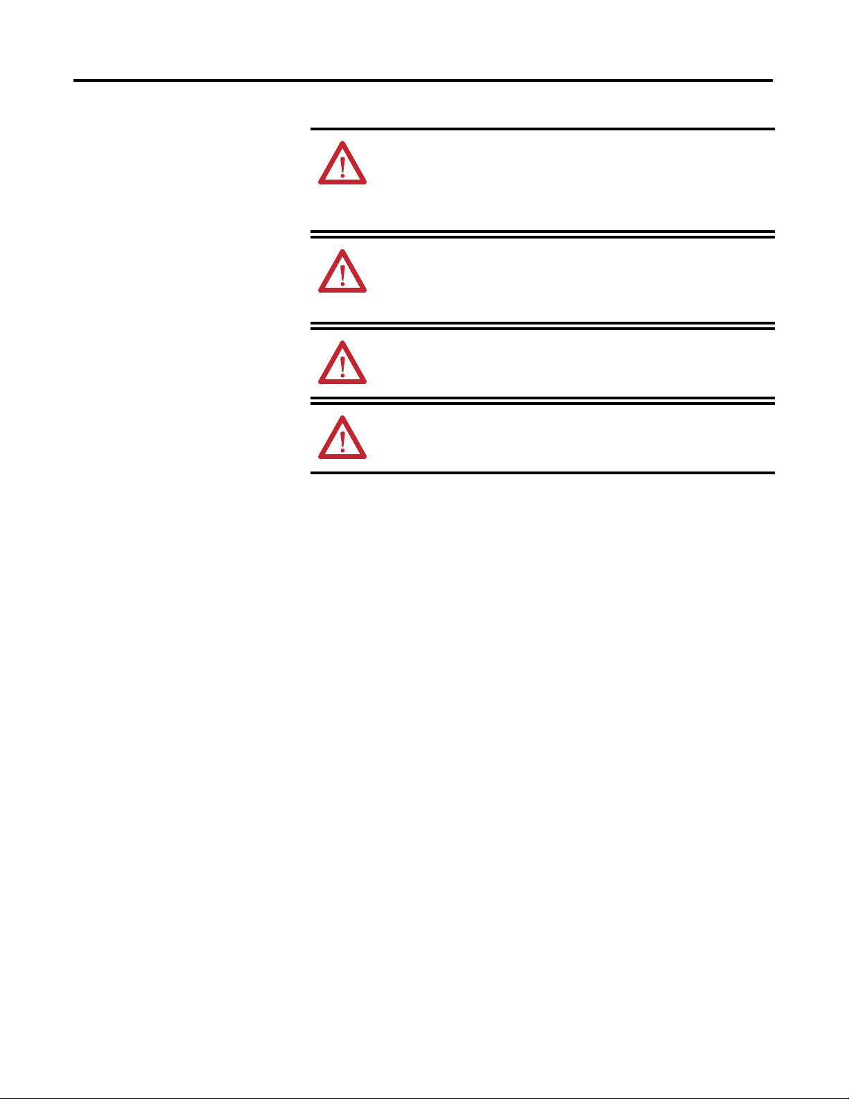
ATT ENTI ON: An incorrectly applied or installed EtherNet/IP
Communications Auxiliary can result in damage to the components or
reduction in product life. Wiring or application errors (e.g., supplying
incorrect or inadequate supply voltage or operating/storing in excessive
ambient temperatures) may result in malfunction of the product.
ATT ENTI ON: Only personnel familiar with the EtherNet/IP
Communications Auxiliary and associated machinery should plan to
install, set up, and maintain the system. Failure to comply may result in
personal injury and/or equipment damage.
ATT ENTI ON: This is a Class A product. In a domestic environment, this
product may cause radio interference in which case the user may be
required to take adequate measures.
ATT ENTI ON: To remain compliant with UL/CSA Certifications, the
DeviceNet power supply must meet NEC Class 2 Requirements.
Rockwell Automation Publication 193-UM014B-EN-P December 2011 9
Chapter 1
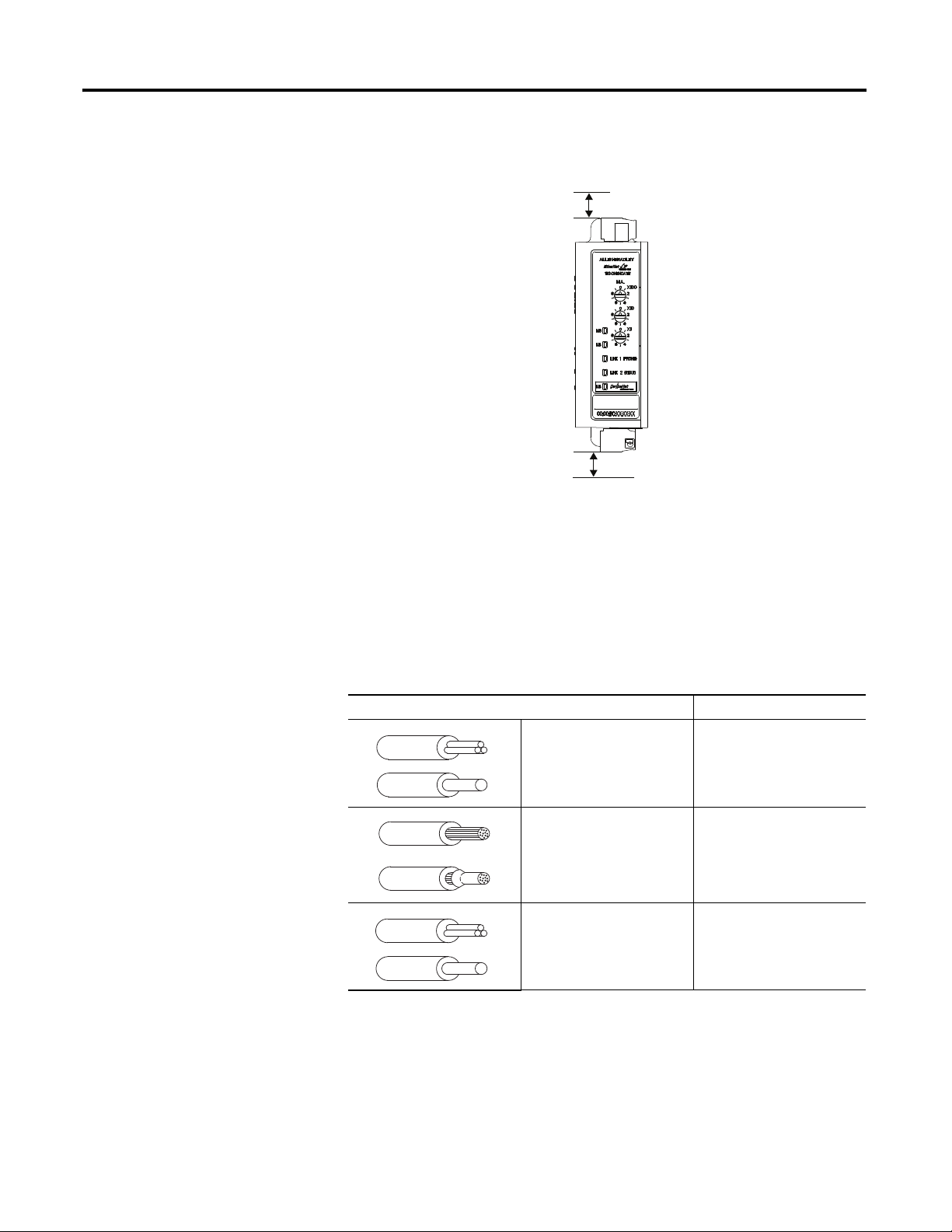
Features
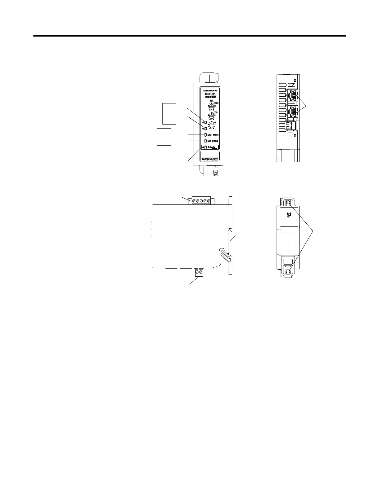
Figure 1 - Features
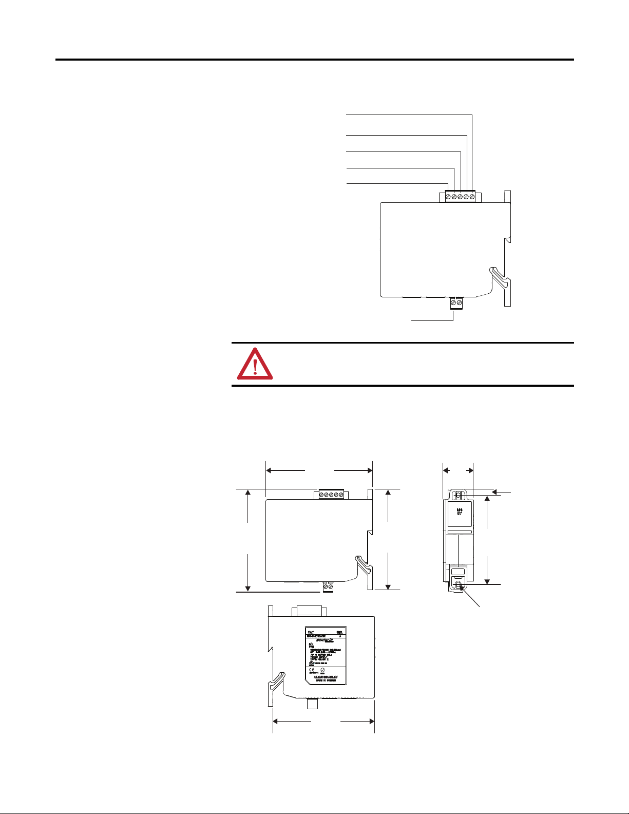
Installation
The EtherNet/IP Communications Auxiliary may be DIN Rail or panel
mounted. To avoid overheating, the unit must be mounted vertically and
requires 37.4 mm (1-1/2 in.) of clearance at the top and bottom to allow proper
air flow. The temperature ratings for the unit will be derated if not mounted in
this manner.
Front View
Module
Ethernet/IP
Network
Front Port Link
Rear Port Link
DeviceNet Network
Status LED
Status
LEDs
Activity
LEDs
Earth Ground Connector
DIN
Rail Mounting
DeviceNet Connector
Panel Mounting
Ethernet Connectors
RJ-45
Side View
Rear View
Top View
10 Rockwell Automation Publication 193-UM014B-EN-P December 2011
Chapter 1
Figure 2 - Installation
Wiring
The EtherNet/IP Communications Auxiliary can accept all forms of DeviceNet
cable. However, DeviceNet shielded cable is recommended. The EtherNet/IP
Communications Auxiliary complies with the Open Device Vendors Association
(ODVA) DeviceNet compliance testing when the distance between end nodes is
100 m or less with 60 or fewer network drops.
Table 1 - Wire & Torque Specifications
Front View
37.44 mm
(1-1/2 in.)
37.44 mm
(1-1/2 in.)
Wire Torque
1X
2X
24…12 AWG
24…16 AWG
5 lb.•in.
1X
2X
0.2…2.5 mm
2
0.25…1 mm
2
0.56 N•m
1X
2X
0.2…2.5 mm
2
0.2…1 mm
2
0.56 N•m
Rockwell Automation Publication 193-UM014B-EN-P December 2011 11
Chapter 1
Figure 3 - Wiring Diagram
Dimensions
Figure 4 - Dimension Diagram
ATTENTION: Use a shielded DeviceNet cable to comply with CISPR 22
and CISPR 24.
DNET (Black)
24V -
CAN L (Blue)
Shield
CAN H (White)
DNET (Red)
24V +
Earth Ground
5.85
(0.23)
105.0
(4.13)
100.5
(3.95)
98.0
(3.86)
110.0
(4.33)
Ø 4.50
(0.16)
87.0
(3.43)
31.3
(1.23)
Dimensions are shown in millimeters (inches).
12 Rockwell Automation Publication 193-UM014B-EN-P December 2011
Chapter 1
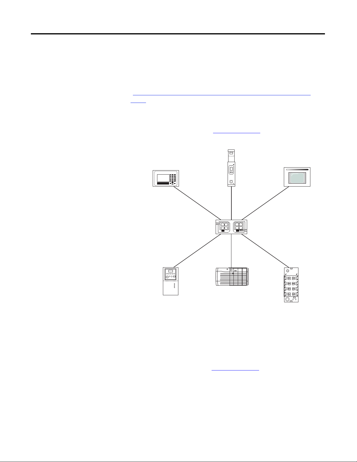
Network Design
The EtherNet/IP Communications Auxiliary is available as a single Ethernet port
(Cat. No. 193-DNENCAT) and dual Ethernet port (Cat. No.
193-DNENCATR) module that has RJ-45 ports to connect to Ethernet cable
CAT5 type or better . Rockwell Automation offers a wide variety of
Allen-Bradley Ethernet patch cables with its Bulletin 1585 line of Ethernet cables
(http://ab.rockwellautomation.com/Connection-Devices/RJ45-Network-
Media).
Both the 193-DNENCAT and 193-DNENCATR devices support a Star
Ethernet topology in which all Ethernet nodes wire back to a central Ethernet
switch, hub, or router as shown in Figure 5 on page 12
.
Figure 5 - Star Ethernet Topology
Rockwell Automation also offers a line of managed and unmanaged
Allen-Bradley Ethernet Switches with its Stratix™ family of Ethernet switches.
Refer to
http://ab.rockwellautomation.com/Networks-and-Communications/
Ethernet-IP-Infrastructure
for more information.
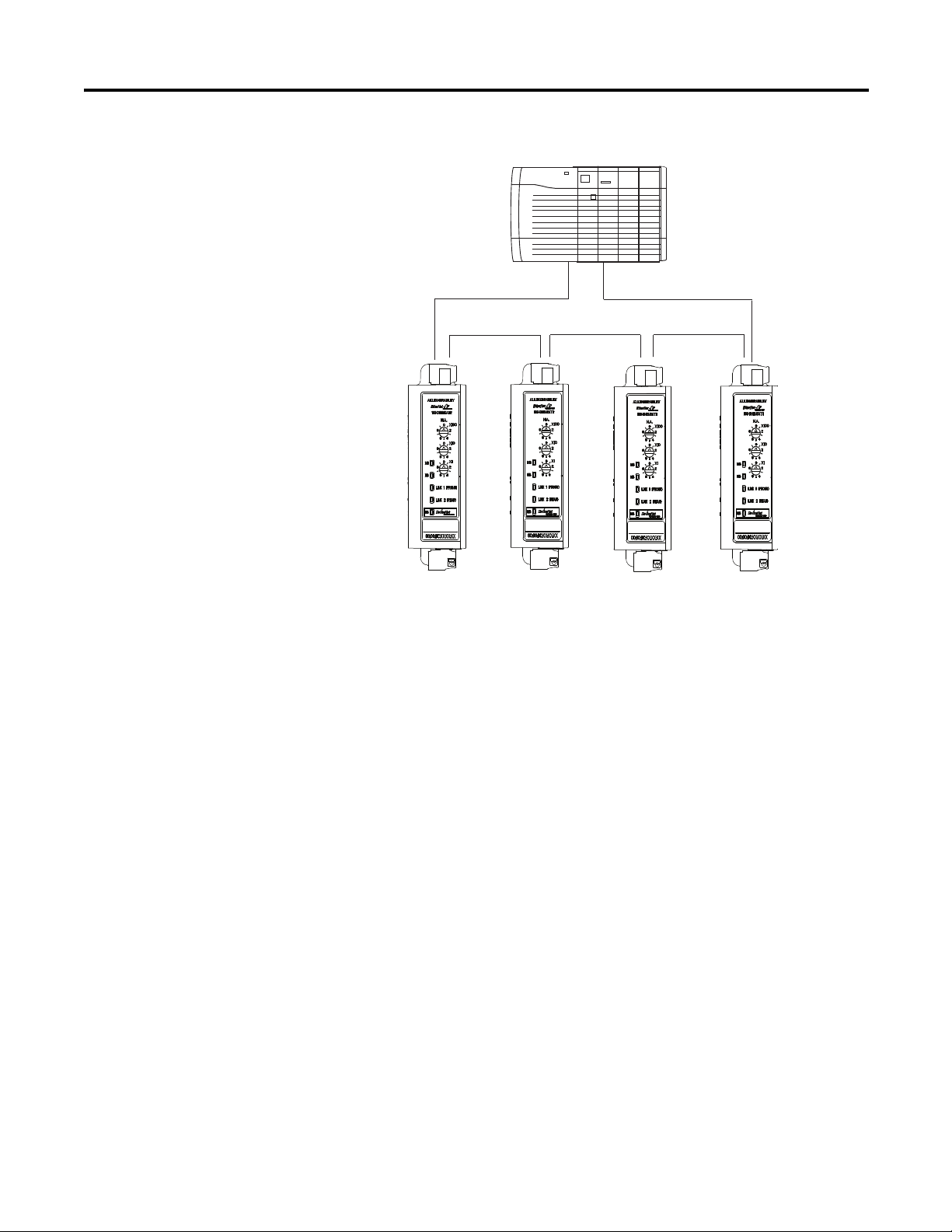
The Cat. No. 193-DNENCATR Module also supports a Ring Ethernet topology
in which all Ethernet nodes are wired in series with one another until a complete
network ring is made as shown in Figure 6 on page 13
.
Rockwell Automation Publication 193-UM014B-EN-P December 2011 13
Chapter 1
Figure 6 - Ring Ethernet Topology
The Cat. No. 193-DNENCATR Module supports Rockwell Automation’s
Device Level Ring (DLR) topology as a slave device in which the EtherNet/IP
network will still continue to communicate in the event that one of the network
chains is disrupted.

14 Rockwell Automation Publication 193-UM014B-EN-P December 2011
Chapter 1

Rockwell Automation Publication 193-UM014B-EN-P December 2011 15
Chapter
2
Configure the EtherNet/IP Communications
Auxiliary
Introduction
This chapter describes how to configure an EtherNet/IP Communications
Auxiliary to operate on an EtherNet/IP network.
When you first install an EtherNet/IP Communications Auxiliary, the module is
Dynamic Host Configuration Protocol (DHCP) enabled.
Determining Network
Parameters
To operate an EtherNet/IP network, you must define these parameters.
Table 2 - EtherNet/IP Network Parameters
If DNS addressing is used or if the module is referenced via a host name in an
MSG instruction, the following parameters must be defined.
Network Parameter Description
IP Address The IP address uniquely identifies the module. The IP address
is in the form xxx.xxx.xxx.xxx where each xxx is a number from
0...255. Do not use the following IP addresses, as these are
reserved values:
• 0.0.0.1...0.255.255.255
• 127.0.0.0...127.255.255.255
• 224.255.255.255...255.255.255.255
Subnet Mask Subnet addressing is an extension of the IP address scheme
that allows a site to use a single network ID for multiple
physical networks. Routing outside of the site continues by
dividing the IP address into a net ID and a host ID via the
class. Inside a site, the subnet mask is used to redivide the IP
address into a custom network ID portion and host ID portion.
NOTE: If you change the subnet mask of an already-
configured module, you must cycle power to the module for
the change to take effect.
Gateway A gateway connects individual physical networks into a
system of networks. When a node needs to communicate
with a node on another network, a gateway transfers the data
between the two networks.
NOTE: Consult with your Ethernet network administrator to determine if these
parameters need to be specified.

16 Rockwell Automation Publication 193-UM014B-EN-P December 2011
Chapter 2
Table 3 - EtherNet/IP Network Parameters for DNS Addressing
Setting the IP Network
Address
An EtherNet/IP Communications Auxiliary ships with DHCP enabled. You can
set the network Internet Protocol (IP) address by using:
• the EtherNet/IP node address selection switches,
• a Bootstrap Protocol (BOOTP)/Dynamic Host Configuration Protocol
(DHCP) server (e.g., the Rockwell Automation BOOTP-DHCP Server
Utility, which is included with Rockwell Software’s RSLinx™ Classic
software), OR
• a web browser and MAC scanner software.
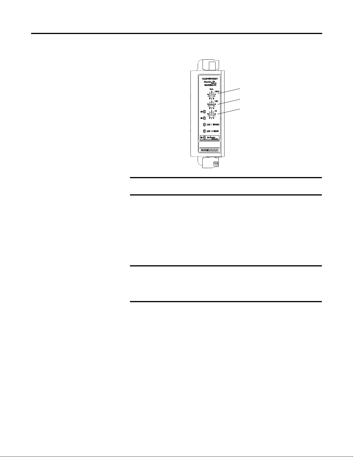
EtherNet/IP Node Address Selection Switches
The EtherNet/IP Communications Auxiliary comes with three node address
selection switches that allow the user to select the last octet for the IP address
192.168.1.xxx.
Network Parameter Description
Host Name A host name is part of a text address that identifies the
module. The full text address of a module is:
host_name.domain_name.
Domain Name A domain name is part of a text address that identifies the
domain in which the module resides. The full text address of a
module is: host_name.domain_name. The domain name has a
48-character limit.
Primary DNS Server Address This identifies any DNS servers used in the network. You must
have a DNS server configured if you specify an SMTP server
with a name. The DNS server converts the domain name or
host name to an IP address that can be used by the network.
For more information on DNS addressing, refer to page 23.
Secondary DNS Server Address
Rockwell Automation Publication 193-UM014B-EN-P December 2011 17
Chapter 2
Figure 7 - Last Octet Selection
When the node address selection switches are set to a value greater than 255, the
IP address is set to DHCP Enabled or programmed for a static IP address.
Assign Network
Parameters via the BOOTP/
DHCP Utility
By default, the EtherNet/IP Communications Auxiliary is DHCP Enabled. The
BOOTP/DHCP utility is a standalone program that is located in the BOOTP-
DHCP Server folder accessed from the Start menu.
This utility recognizes DHCP-enabled devices and provides an interface to
configure a static IP address for each device.
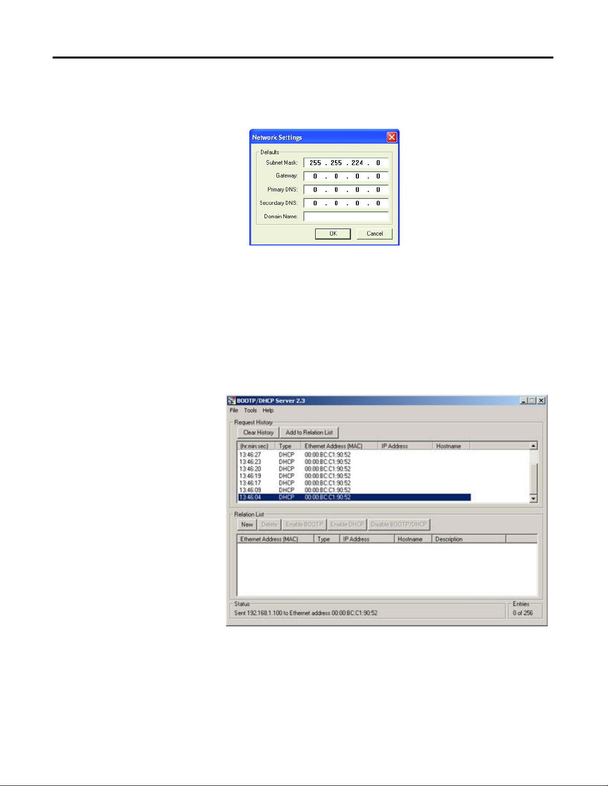
To assign network parameters via the BOOTP/DHCP utility, perform this
procedure:
1. Execute the BOOTP/DHCP software.
2. Choose Tool >Network Settings.
EXAMPLE
When the top dial is set to 1, the middle dial is set to 2, and the bottom
dial is set to 3, the resulting IP address is: 192.168.1.123.
x 100 Digit
x 1 Digit
x 10 Digit
IMPORTANT
Before starting the BOOTP/DHCP utility: Make sure you have the
hardware MAC ID of the module, which is printed on the front of the
EtherNet/IP Communications Auxiliary. The MAC ID has a format
similar to: 00-0b-db-14-55-35.
18 Rockwell Automation Publication 193-UM014B-EN-P December 2011
Chapter 2
3. If appropriate for the network, type the subnet mask, gateway address,
primary/secondary server addresses, and domain name in their respective
fields.
4. Click OK.
The Request History panel displays the hardware addresses of modules
issuing BOOTP or DHCP requests.
5. Double-click the MAC address of the module to be configured.
NOTE: The MAC address is printed on the front of the EtherNet/IP Communications
Auxiliary. The format of the hardware address resembles:
00-0b-db-14-55-35

Rockwell Automation Publication 193-UM014B-EN-P December 2011 19
Chapter 2
The New Entry window appears with the module’s Ethernet Address
(MAC).
6. Type the IP address, host name, and a module description.
7. Click OK.
8. Cycle power to the module by removing and reapplying the DeviceNet
connector.
9. To permanently assign this configuration to the module: Select the module
in the Relation List panel and click Disable BOOTP/DHCP.
When module power is cycled, it uses the assigned configuration and does
not issue a DHCP request.
If you do not click Disable BOOTP/DHCP, on a power cycle, the module
clears the current IP configuration and will again begin sending DHCP
requests.
Assign Network
Parameters Via a Web
Browser & MAC Scanner
Software
In the event that a user does not have access to a DHCP software utility, a user
can assign network parameters via a web browser (e.g., Microsoft® Internet
Explorer) and Media Access Control (MAC) scanner software (e.g., MAC
Scanner from Colasoft® - http://www.colasoft.com/
). Follow these steps to
configure the module using this method.
1. Locate and identify the MAC ID printed on the label of the EtherNet/IP
Communications Auxiliary. This address has a format that is similar to:
00-0b-db-14-55-35
2. Connect the EtherNet/IP Communications Auxiliary to the same wide
area network (WAN) as your personal computer.
3. Initiate the MAC scanner software.
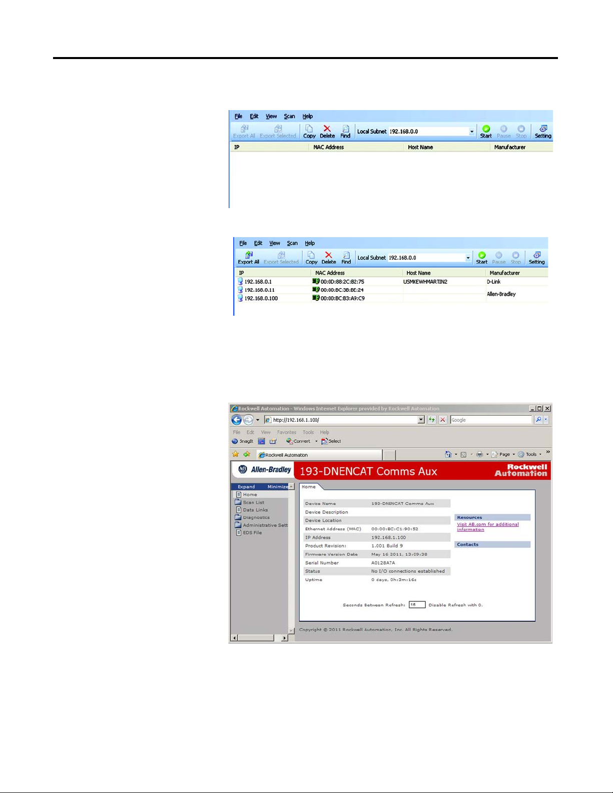
20 Rockwell Automation Publication 193-UM014B-EN-P December 2011
Chapter 2
4. Select the appropriate subnet to scan for available MAC addresses.
5. Scan the Subnet for all available MAC addresses.
6. Identify the IP address assigned to the MAC ID of the EtherNet/IP
Communications Auxiliary. The IP address will have a format that is
similar to 192.168.0.100.
7. Open a web browser and type the IP address on the address line to view the
internal web server of the EtherNet/IP Communications Auxiliary.
8. Select Administration Settings>Network Configuration to change the IP
address of the EtherNet/IP Communications Auxiliary to a static IP
address.
Rockwell Automation Publication 193-UM014B-EN-P December 2011 21
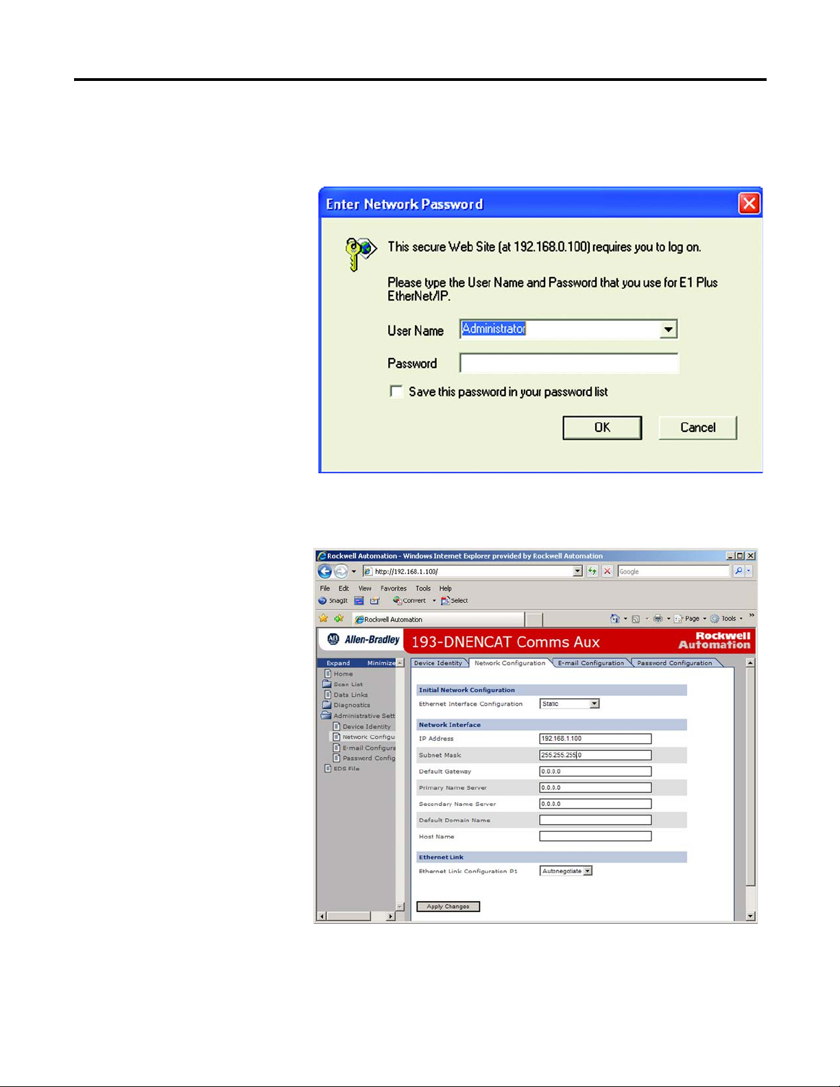
Chapter 2
9. The module will prompt the user for a User Name and Password. Type
“Administrator” as the user name, leave the password field blank, then click
OK.
10. Assign the appropriate network settings per the recommendation of the
network administrator for the network that this module will be
communicating on and click Apply.
11. Remove and reapply the DeviceNet connector to allow the
communications changes to take affect.

22 Rockwell Automation Publication 193-UM014B-EN-P December 2011
Chapter 2
Other Factors to Consider When Assigning Network Parameters
There are other factors to consider when assigning networks parameters, which
include the:
• network isolation from or integration into the plant/enterprise network.
• network size.
For large networks, even isolated networks, it might be more convenient
and safer to use a BOOTP/DHCP server rather than RSLinx software.
The BOOTP/DHCP server also limits the possibility of assigning
duplicate IP addresses.
• company policies and procedures associated with plant floor network
installation and maintenance.
• level of involvement by information technology personnel in plant floor
network installation and maintenance.
• type of training offered to control engineers and maintenance personnel.
If the Rockwell Automation BOOTP or DHCP server is used in an uplinked
subnet where an enterprise DHCP server exists, a module may get an address
from the enterprise server before the Rockwell Automation utility even sees the
module. In this case, disconnect the uplink to set the address and configure the
module to retain its static address before reconnecting to the uplink. This is not a
problem if you have node names configured in the module and leave DHCP
enabled.
Duplicate IP Address
Detection
When you change the IP address or connect the module to an EtherNet/IP
network, the module checks to make sure that the IP address assigned to this
module does not match the address of any other network device. If the module
determines that another device on the network with a matching IP address, the
EtherNet/IP port of the module goes into conflict mode where the Network
Status LED indicator is solid red.
To resolve this conflict, use the instructions below to change the IP address of the
module. Then, cycle power to the module or reset the modules by disconnecting
and then reconnecting the Ethernet cable.
Two modules could possibly detect a conflict simultaneously. If this occurs,
perform this procedure.
1. Remove the module with the incorrect IP address and correct its conflict.
2. Cycle power or disconnect the Ethernet cable from the second module and
reconnect it.
ATT ENTI ON: The EtherNet/IP Communications Auxiliary must be
assigned a fixed network address. The IP address of this module must not
be dynamically provided. Failure to observe this precaution may result in
unintended machine motion or loss of process control.

Rockwell Automation Publication 193-UM014B-EN-P December 2011 23
Chapter 2
Behavior of Modules With Duplicate IP Addresses
Devices in conflict over an IP address behave differently depending on whether
connections have been established to either of the modules and whether both
modules support duplicate IP address detection.
Table 4 - Device Conflict over Duplicate IP Addresses
DNS Addressing
To further qualify a module’s address, use DNS addressing to specify a host name
for a module, which also includes specifying a domain name and DNS servers.
DNS addressing makes it possible to set up similar network structures and IP
address sequences under different domains.
DNS addressing is only necessary if you refer to the module by host name, such as
in path descriptions in MSG instructions.
To use DNS addressing, perform this procedure.
1. Assign a host name to the module.
2. Configure the module's parameters.
3. In addition to the IP address, subnet mask, and gateway address, configure
a host name for the module, domain name, and primary/secondary DNS
server addresses.
Electronic Data Sheet (EDS)
File Installation
Before the EtherNet/IP Communications Auxiliary is configured to
communicate on an EtherNet/IP network, it must be registered to the software
that configures the network (e.g., Rockwell Automation RSLinx Classic and
RSNetWorx for EtherNet/IP software). A user registers the module by installing
an EDS file. The EDS file for the EtherNet/IP Communications Auxiliary can
be obtained from one of two locations:
If then
both modules support duplicate IP
address detection,
the first started module uses and retains its IP address.
The other module will detect a conflict, give up the IP
address and enter conflict mode.
both modules support duplicate IP
address detection and are started at
roughly the same time,
one of the modules surrenders the IP address and enters
conflict mode.
one module supports duplicate IP address
detection and a second module does not,
the second module generally keeps its IP address,
regardless of which module first obtains the IP address.
The module that supports duplicate IP address detection
will detect the conflict and give up the IP address.
NOTE: Contact the network administrator ro have a host name assigned. Valid host
names should be IEC-1131-3 compliant.
24 Rockwell Automation Publication 193-UM014B-EN-P December 2011
Chapter 2
• embedded in the module OR
• the Allen-Bradley EDS file download website.
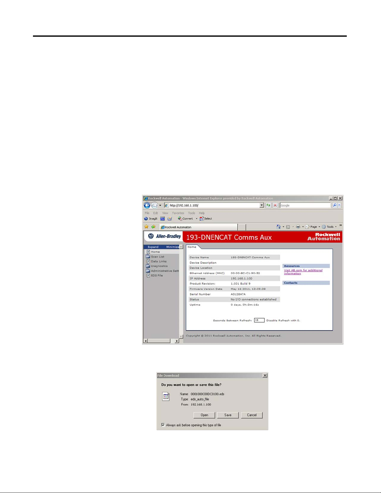
Download the EDS File
Embedded in the Module
The EDS file for the EtherNet/IP Communications Auxiliary is embedded
within the module. After the IP address for the module has been configured,
connect the module to same Ethernet network as a personal computer. Using a
web browser on the personal computer, a user can download the EDS file using a
web browser by following these steps:
1. Type the IP address of the EtherNet/IP Communications Auxiliary on the
address line of the web browser.
2. Select EDS File link
3. Click Save to save the EDS file to the personal computer.
Rockwell Automation Publication 193-UM014B-EN-P December 2011 25
Chapter 2
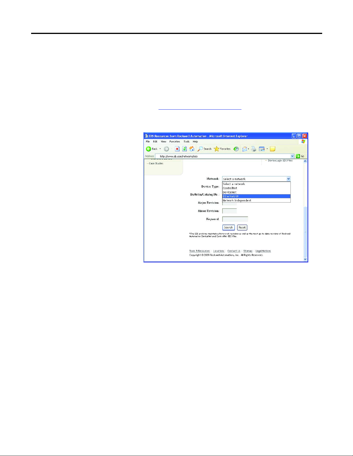
From the EDS File Download Site
The EDS file for the EtherNet/IP Communications Auxiliary can also be
downloaded from the Allen-Bradley EDS File download site. Using a web
browser on the personal computer that is connected to the internet, a user can
download the EDS file by following these steps:
1. Ty p e http://www.ab.com/networks/eds
on the address line of the web
browser.
2. Select EtherNet/IP as the network type, then click Search.
3. Locate the EDS file for the EtherNet/IP Communications Auxiliary and
download it to the personal computer.
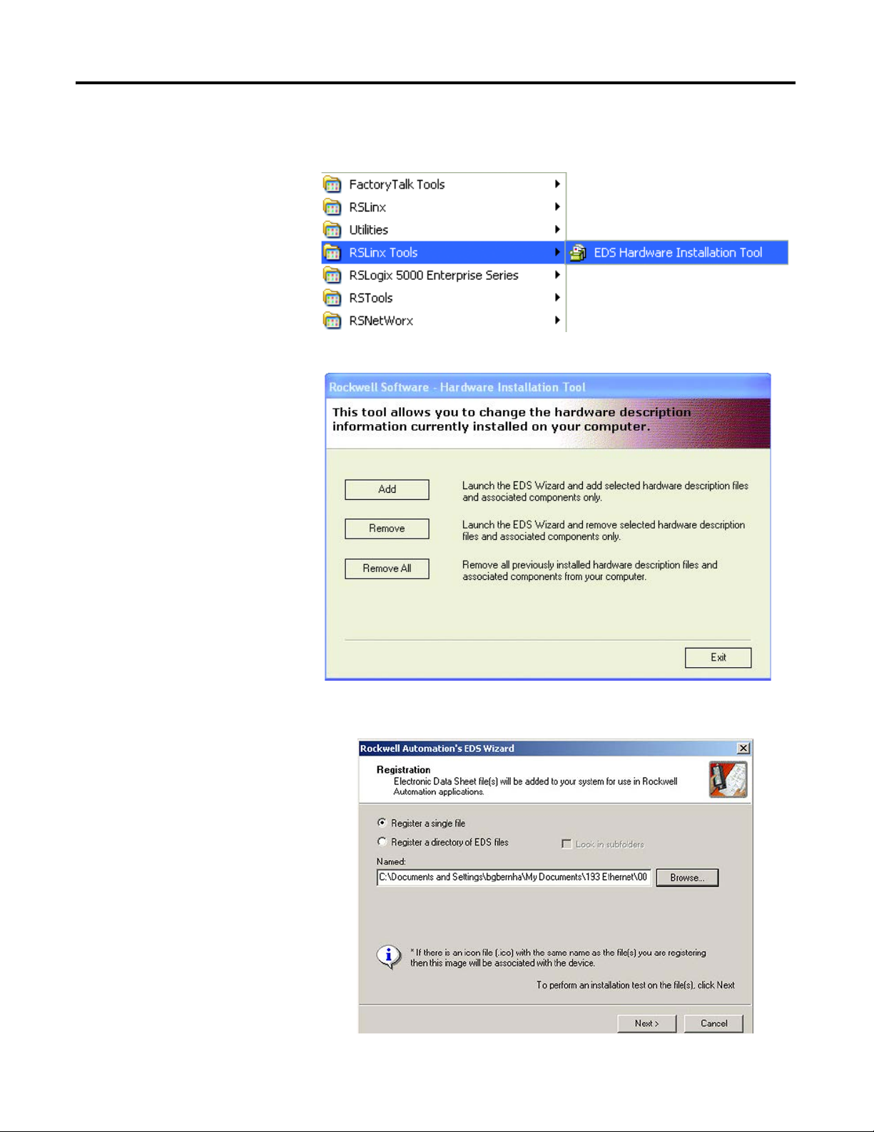
Register the EDS File
After the EDS file has been downloaded, a user will need to register the EDS file
with the software that configures the EtherNet/IP network. The following
example lists the steps needed to register an EDS file with Rockwell Automation’s
RSLinx Classic software.
26 Rockwell Automation Publication 193-UM014B-EN-P December 2011
Chapter 2
1. Start the EDS Hardware Installation Tool located at Start>Programs>
Rockwell Software>RSLinx Tools.
2. Click Add to register a new device.
3. Click the “Register a single file” radio button, then browse to the location
where the EDS file is located. Click Next.
Rockwell Automation Publication 193-UM014B-EN-P December 2011 27
Chapter 2
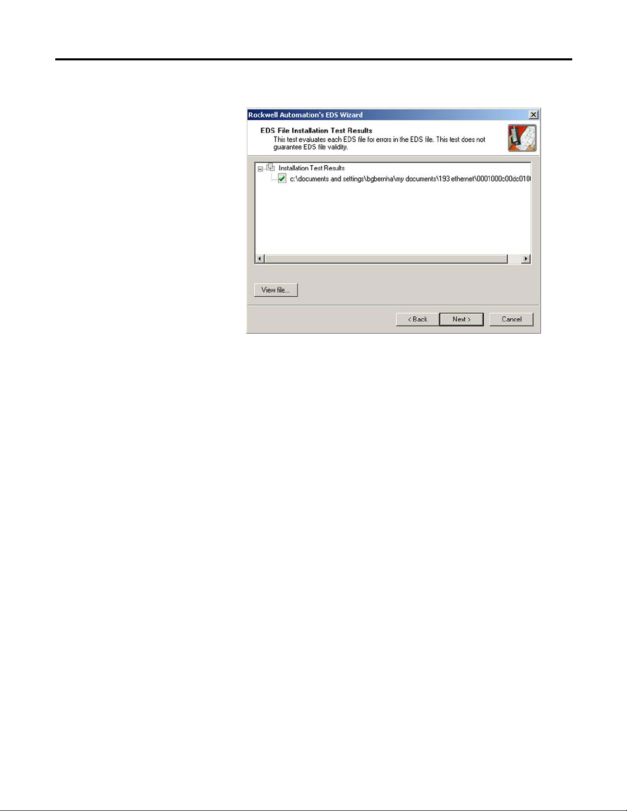
4. Click Next to accept the installation test results.
28 Rockwell Automation Publication 193-UM014B-EN-P December 2011
Chapter 2
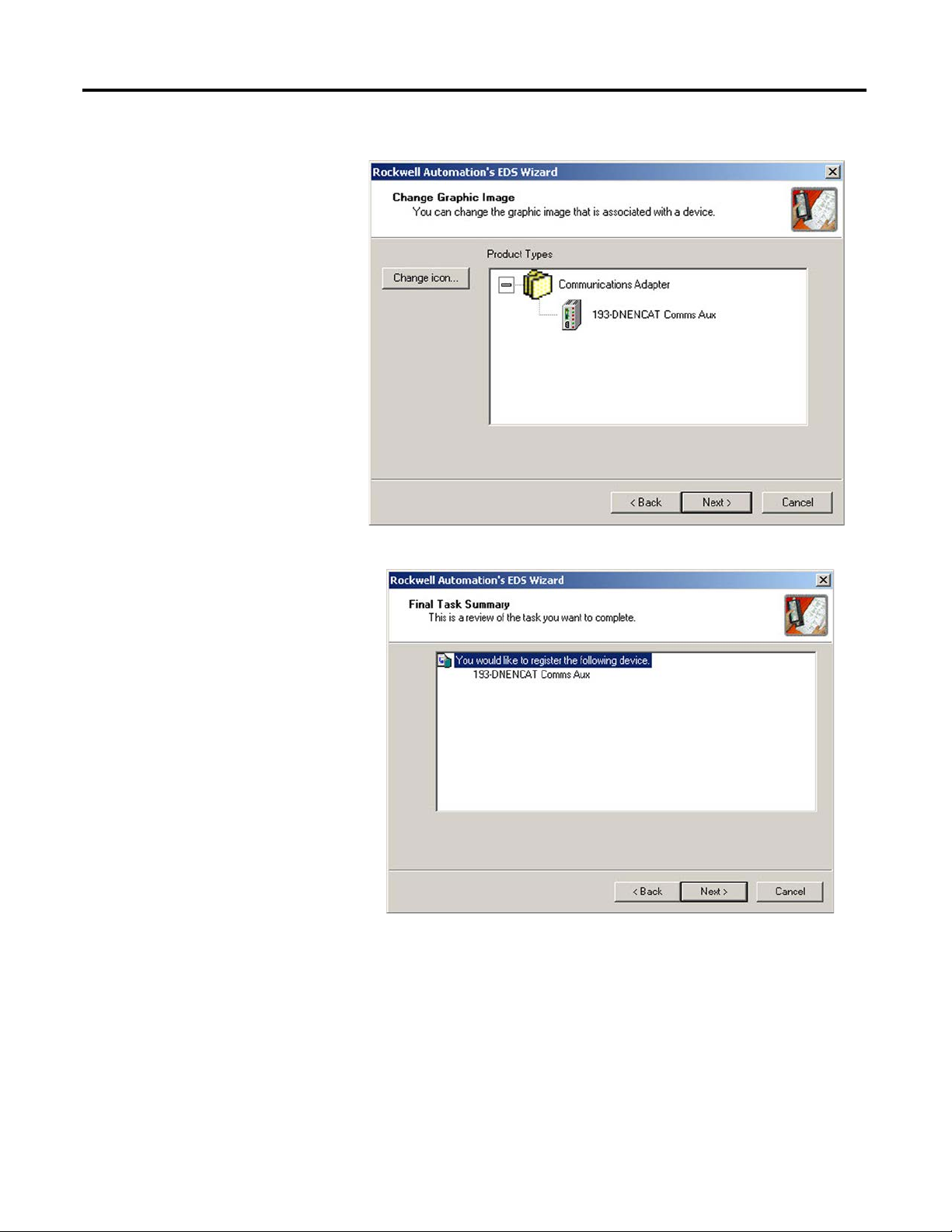
5. Click Next to accept the graphic image.
6. Click Next to register the device.
Rockwell Automation Publication 193-UM014B-EN-P December 2011 29
Chapter 2
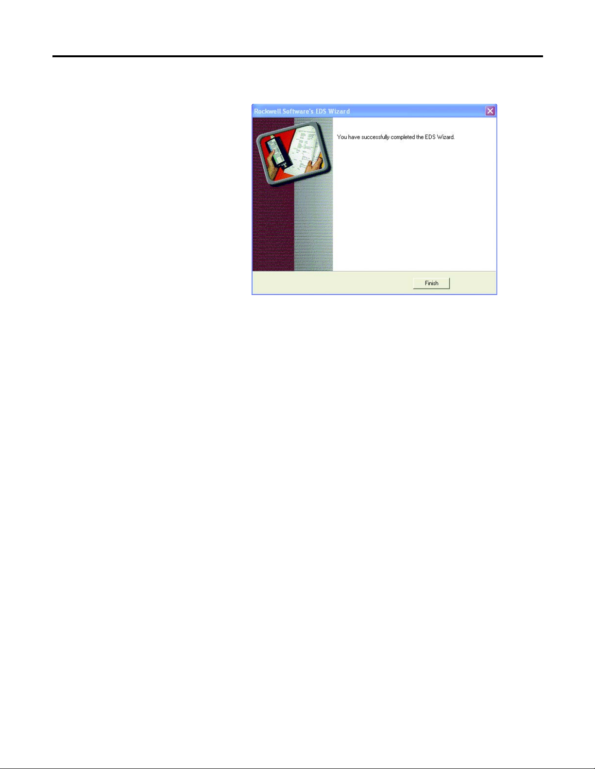
7. Click Finish to successfully register the module.

30 Rockwell Automation Publication 193-UM014B-EN-P December 2011
Chapter 2
Loading...