


 Loading...
User Manual
PowerFlex 25-COMM-E2P Dual-Port EtherNet/IP Adapter

Important User Information
Solid-state equipment has operational characteristics differing from those of electromechanical equipment. Safety Guidelines for the Application, Installation and Maintenance of Solid State Controls (publication SGI-1.1 available from your local Rockwell Automation® sales office or online at http://www.rockwellautomation.com/literature/) describes some important differences between solid-state equipment and hard-wired electromechanical devices. Because of this difference, and also because of the wide variety of uses for solid-state equipment, all persons responsible for applying this equipment must satisfy themselves that each intended application of this equipment is acceptable.
In no event will Rockwell Automation, Inc. be responsible or liable for indirect or consequential damages resulting from the use or application of this equipment.
The examples and diagrams in this manual are included solely for illustrative purposes. Because of the many variables and requirements associated with any particular installation, Rockwell Automation, Inc. cannot assume responsibility or liability for actual use based on the examples and diagrams.
No patent liability is assumed by Rockwell Automation, Inc. with respect to use of information, circuits, equipment, or software described in this manual.
Reproduction of the contents of this manual, in whole or in part, without written permission of Rockwell Automation, Inc., is prohibited.
Throughout this manual, when necessary, we use notes to make you aware of safety considerations.
WARNING: Identifies information about practices or circumstances that can cause an explosion in a hazardous environment, which may lead to personal injury or death, property damage, or economic loss.
ATTENTION: Identifies information about practices or circumstances that can lead to personal injury or death, property damage, or economic loss. Attentions help you identify a hazard, avoid a hazard, and recognize the consequence.
SHOCK HAZARD: Labels may be on or inside the equipment, for example, a drive or motor, to alert people that dangerous voltage may be present.
BURN HAZARD: Labels may be on or inside the equipment, for example, a drive or motor, to alert people that surfaces may reach dangerous temperatures.
ARC FLASH HAZARD: Labels may be on or inside the equipment, for example, a motor control center, to alert people to potential Arc Flash. Arc Flash will cause severe injury or death. Wear proper Personal Protective Equipment (PPE). Follow ALL Regulatory requirements for safe work practices and for Personal Protective Equipment (PPE).
IMPORTANT Identifies information that is critical for successful application and understanding of the product.
Allen-Bradley, Rockwell Automation, Rockwell Software, PowerFlex, Studio 5000, and Connected Components Workbench are trademarks of Rockwell Automation, Inc.
Trademarks not belonging to Rockwell Automation are property of their respective companies.

|
|
Table of Contents |
|
Important User Information . . . . . . . . . . . . . . . . . . . . . . . . . . . . . . |
. . . . . . . . . 2 |
|
Preface |
|
Overview |
Recommended Documentation . . . . . . . . . . . . . . . . . . . . . . . . . . . . |
. . . . . . . . 7 |
|
Manual Conventions . . . . . . . . . . . . . . . . . . . . . . . . . . . . . . . . . . . . . . |
. . . . . . . . 7 |
|
Chapter 1 |
|
Getting Started |
Components. . . . . . . . . . . . . . . . . . . . . . . . . . . . . . . . . . . . . . . . . . . . . . |
. . . . . . . . 9 |
|
Features . . . . . . . . . . . . . . . . . . . . . . . . . . . . . . . . . . . . . . . . . . . . . . . . . . |
. . . . . . . 10 |
|
Understanding Parameter Types. . . . . . . . . . . . . . . . . . . . . . . . . . . . |
. . . . . . . 10 |
|
Compatible Products . . . . . . . . . . . . . . . . . . . . . . . . . . . . . . . . . . . . . . |
. . . . . . . 11 |
|
Required Equipment . . . . . . . . . . . . . . . . . . . . . . . . . . . . . . . . . . . . . . |
. . . . . . . 11 |
|
Safety Precautions . . . . . . . . . . . . . . . . . . . . . . . . . . . . . . . . . . . . . . . . . |
. . . . . . . 12 |
|
Quick Start . . . . . . . . . . . . . . . . . . . . . . . . . . . . . . . . . . . . . . . . . . . . . . . |
. . . . . . . 13 |
|
Chapter 2 |
|
Installing the Adapter |
Preparing for Set-Up . . . . . . . . . . . . . . . . . . . . . . . . . . . . . . . . . . . . . . |
. . . . . . . 15 |
|
Setting the Node Address . . . . . . . . . . . . . . . . . . . . . . . . . . . . . . . . . . |
. . . . . . . 16 |
|
Connecting the Adapter to the Drive . . . . . . . . . . . . . . . . . . . . . . . |
. . . . . . . 18 |
|
Connecting the Adapter to the Network . . . . . . . . . . . . . . . . . . . . |
. . . . . . . 20 |
|
Applying Power . . . . . . . . . . . . . . . . . . . . . . . . . . . . . . . . . . . . . . . . . . . |
. . . . . . . 22 |
|
Commissioning the Adapter . . . . . . . . . . . . . . . . . . . . . . . . . . . . . . . |
. . . . . . . 24 |
|
Chapter 3 |
|
Configuring the Adapter |
Configuration Tools. . . . . . . . . . . . . . . . . . . . . . . . . . . . . . . . . . . . . . . |
. . . . . . . 25 |
|
Using the Drive Keypad Interface to Access Parameters . . . . . . |
. . . . . . . 25 |
|
Using the PowerFlex 4-Class HIM to Access Parameters. . . . . . |
. . . . . . . 27 |
|
Setting the Adapter Node Address . . . . . . . . . . . . . . . . . . . . . . . . . . |
. . . . . . . 27 |
|
Using a BOOTP or DHCP Server . . . . . . . . . . . . . . . . . . . . . . . . . . |
. . . . . . . 28 |
|
Using Adapter Parameters . . . . . . . . . . . . . . . . . . . . . . . . . . . . . . . . . |
. . . . . . . 31 |
|
Setting the Data Rate . . . . . . . . . . . . . . . . . . . . . . . . . . . . . . . . . . . . . . |
. . . . . . . 32 |
|
Using Master-Slave Hierarchy . . . . . . . . . . . . . . . . . . . . . . . . . . . . . . |
. . . . . . . 33 |
|
Setting a Fault Action . . . . . . . . . . . . . . . . . . . . . . . . . . . . . . . . . . . . . |
. . . . . . . 34 |
|
Resetting the Adapter . . . . . . . . . . . . . . . . . . . . . . . . . . . . . . . . . . . . . |
. . . . . . . 36 |
|
Restoring Adapter Parameters to Factory Defaults . . . . . . . . . . . |
. . . . . . . 36 |
|
Viewing the Adapter Status Using Parameters . . . . . . . . . . . . . . . |
. . . . . . . 37 |
|
Updating the Adapter Firmware. . . . . . . . . . . . . . . . . . . . . . . . . . . . |
. . . . . . . 37 |
|
Chapter 4 |
|
Configuring the I/O |
Using RSLinx Classic . . . . . . . . . . . . . . . . . . . . . . . . . . . . . . . . . . . . . . |
. . . . . . . 39 |
|
CompactLogix Example . . . . . . . . . . . . . . . . . . . . . . . . . . . . . . . . . . . |
. . . . . . . 40 |
|
Limitations in Using MicroLogix 1100/1400 . . . . . . . . . . . . . . . . |
. . . . . . . 62 |
Rockwell Automation Publication 520COM-UM003A-EN-E - June 2013 |
3 |

Table of Contents |
|
|
|
Chapter 5 |
|
Using the I/O |
About I/O Messaging . . . . . . . . . . . . . . . . . . . . . . . . . . . . . . . . . . . . . . . . . . . . |
63 |
|
Understanding the I/O Image . . . . . . . . . . . . . . . . . . . . . . . . . . . . . . . . . . . . . |
64 |
|
Using Logic Command/Status . . . . . . . . . . . . . . . . . . . . . . . . . . . . . . . . . . . . |
65 |
|
Using Reference/Feedback . . . . . . . . . . . . . . . . . . . . . . . . . . . . . . . . . . . . . . . . |
65 |
|
Using Datalinks . . . . . . . . . . . . . . . . . . . . . . . . . . . . . . . . . . . . . . . . . . . . . . . . . . |
66 |
|
Example Ladder Logic Program Information . . . . . . . . . . . . . . . . . . . . . . . |
67 |
|
CompactLogix Example . . . . . . . . . . . . . . . . . . . . . . . . . . . . . . . . . . . . . . . . . . |
67 |
|
Chapter 6 |
|
Using Explicit Messaging |
About Explicit Messaging . . . . . . . . . . . . . . . . . . . . . . . . . . . . . . . . . . . . . . . . . |
73 |
|
Performing Explicit Messaging . . . . . . . . . . . . . . . . . . . . . . . . . . . . . . . . . . . . |
74 |
|
CompactLogix Controller Examples . . . . . . . . . . . . . . . . . . . . . . . . . . . . . . . |
74 |
|
Chapter 7 |
|
Using Multi-Drive Mode |
Single-Drive Mode vs. Multi-Drive Mode . . . . . . . . . . . . . . . . . . . . . . . . . . |
87 |
|
System Wiring . . . . . . . . . . . . . . . . . . . . . . . . . . . . . . . . . . . . . . . . . . . . . . . . . . . |
89 |
|
Understanding the I/O Image . . . . . . . . . . . . . . . . . . . . . . . . . . . . . . . . . . . . . |
90 |
|
Configuring the RS-485 Network . . . . . . . . . . . . . . . . . . . . . . . . . . . . . . . . . |
91 |
|
Using Multi-Drive Add-On Profile . . . . . . . . . . . . . . . . . . . . . . . . . . . . . . . . |
91 |
|
Multi-Drive Ladder Logic Program for Generic Profile . . . . . . . . . . . . . |
102 |
|
CompactLogix Controller Example Using Generic Profile . . . . . . . . . . |
103 |
|
Multi-Drive Mode Explicit Messaging . . . . . . . . . . . . . . . . . . . . . . . . . . . . |
111 |
|
Additional Information. . . . . . . . . . . . . . . . . . . . . . . . . . . . . . . . . . . . . . . . . . |
112 |
|
Chapter 8 |
|
Troubleshooting |
Understanding the Status Indicators . . . . . . . . . . . . . . . . . . . . . . . . . . . . . . |
115 |
|
PORT Status Indicator . . . . . . . . . . . . . . . . . . . . . . . . . . . . . . . . . . . . . . . . . . |
116 |
|
MOD Status Indicator. . . . . . . . . . . . . . . . . . . . . . . . . . . . . . . . . . . . . . . . . . . |
116 |
|
NET A Status Indicator . . . . . . . . . . . . . . . . . . . . . . . . . . . . . . . . . . . . . . . . . |
116 |
|
NET B Status Indicator. . . . . . . . . . . . . . . . . . . . . . . . . . . . . . . . . . . . . . . . . . |
117 |
|
Viewing Adapter Diagnostic Items. . . . . . . . . . . . . . . . . . . . . . . . . . . . . . . . |
117 |
|
Viewing and Clearing Events . . . . . . . . . . . . . . . . . . . . . . . . . . . . . . . . . . . . . |
120 |
|
Appendix A |
|
Specifications |
Communication . . . . . . . . . . . . . . . . . . . . . . . . . . . . . . . . . . . . . . . . . . . . . . . . |
123 |
|
Electrical . . . . . . . . . . . . . . . . . . . . . . . . . . . . . . . . . . . . . . . . . . . . . . . . . . . . . . . |
123 |
|
Mechanical . . . . . . . . . . . . . . . . . . . . . . . . . . . . . . . . . . . . . . . . . . . . . . . . . . . . . |
123 |
|
Environmental . . . . . . . . . . . . . . . . . . . . . . . . . . . . . . . . . . . . . . . . . . . . . . . . . . |
123 |
|
Regulatory Compliance . . . . . . . . . . . . . . . . . . . . . . . . . . . . . . . . . . . . . . . . . . |
123 |
|
Appendix B |
|
Adapter Parameters |
Device Parameters . . . . . . . . . . . . . . . . . . . . . . . . . . . . . . . . . . . . . . . . . . . . . . . |
125 |
4 |
Rockwell Automation Publication 520COM-UM003A-EN-E - June 2013 |

|
|
Table of Contents |
|
Appendix C |
|
EtherNet/IP Objects |
Supported Data Types . . . . . . . . . . . . . . . . . . . . . . . . . . . . . . . . . . . . |
. . . . . . . 129 |
|
Identity Object. . . . . . . . . . . . . . . . . . . . . . . . . . . . . . . . . . . . . . . . . . . . |
. . . . . . 130 |
|
Assembly Object . . . . . . . . . . . . . . . . . . . . . . . . . . . . . . . . . . . . . . . . . . |
. . . . . . 132 |
|
Register Object. . . . . . . . . . . . . . . . . . . . . . . . . . . . . . . . . . . . . . . . . . . . |
. . . . . . 133 |
|
Parameter Object . . . . . . . . . . . . . . . . . . . . . . . . . . . . . . . . . . . . . . . . . |
. . . . . . 136 |
|
PCCC Object . . . . . . . . . . . . . . . . . . . . . . . . . . . . . . . . . . . . . . . . . . . . |
. . . . . . 139 |
|
DPI Device Object . . . . . . . . . . . . . . . . . . . . . . . . . . . . . . . . . . . . . . . . |
. . . . . . 142 |
|
DPI Parameter Object . . . . . . . . . . . . . . . . . . . . . . . . . . . . . . . . . . . . . |
. . . . . . 145 |
|
DPI Fault Object. . . . . . . . . . . . . . . . . . . . . . . . . . . . . . . . . . . . . . . . . . |
. . . . . . 151 |
|
TCP/IP Interface Object . . . . . . . . . . . . . . . . . . . . . . . . . . . . . . . . . . |
. . . . . . 153 |
|
Ethernet Link Object . . . . . . . . . . . . . . . . . . . . . . . . . . . . . . . . . . . . . . |
. . . . . . 155 |
|
Appendix D |
|
Logic Command/Status Words: |
Logic Command Word . . . . . . . . . . . . . . . . . . . . . . . . . . . . . . . . . . . . |
. . . . . . 157 |
PowerFlex 525 Drives |
Logic Status Word . . . . . . . . . . . . . . . . . . . . . . . . . . . . . . . . . . . . . . . . |
. . . . . . 158 |
|
Glossary |
|
|
Index |
|
Rockwell Automation Publication 520COM-UM003A-EN-E - June 2013 |
5 |

Table of Contents
Notes:
6 |
Rockwell Automation Publication 520COM-UM003A-EN-E - June 2013 |

Preface
Recommended
Documentation
Overview
This manual provides information about the Dual-port EtherNet/IP adapter and using it with PowerFlex 520-series drives for network communication.
For information on… |
See page… |
|
|
Recommended Documentation |
7 |
|
|
Manual Conventions |
7 |
|
|
All the recommended documentation listed in this section is available online at http://www.rockwellautomation.com/literature.
The following publications provide additional information:
For... |
See... |
Publication |
|
|
|
EtherNet/IP™ |
EtherNet/IP Media Planning and Installation Manual(1) |
ODVA Pub. 148 |
|
EtherNet/IP Network Infrastructure Guidelines(1) |
ODVA Pub. 35 |
|
EtherNet/IP Network Configuration User Manual |
ENET-UM001 |
|
|
|
|
Troubleshoot EtherNet/IP Networks |
ENET-AT003 |
|
|
|
|
EtherNet/IP Design, Commissioning, and |
IASIMP-QR023 |
|
Troubleshooting Quick Reference Drawings |
|
|
Ethernet Design Considerations Reference Manual |
ENET-RM002 |
|
|
|
PowerFlex®520-Series Drives |
PowerFlex 525 Adjustable Frequency AC Drive User Manual |
520-UM001 |
|
|
|
|
PowerFlex 520-Series Communication Adapters Installation |
520COM-IN001 |
|
Instructions |
|
HIM (Human Interface Module) |
PowerFlex 4-Class HIM (DSI) Quick Reference |
22HIM-QR001 |
|
|
|
RSLinx® Classic |
RSLinx Classic Getting Results Guide(2) |
LINX-GR001 |
RSLogix™ 5000 |
RSLogix 5000 online help(2) |
– |
CompactLogix™ 5370 |
CompactLogix 5370 Controllers User Manual (1769-L36ERM) |
1769-UM021 |
|
|
|
MicroLogix™ 1100 |
MicroLogix 1100 Programmable Controllers User Manual |
1763-UM001 |
|
|
|
MicroLogix™ 1400 |
MicroLogix 1400 Programmable Controllers User Manual |
1766-UM001 |
|
|
|
(1)For ODVA publications, see the ODVA Ethernet/IP library at http://odva.org/Home/ODVATECHNOLOGIES/EtherNetIP/EtherNetIPLibrary/tabid/76/lng/en-US/Default.aspx
(2)The online help is installed with the software.
Manual Conventions
The following conventions are used throughout this manual:
•Parameter names are shown in the format Device parameter xx [*] or Host parameter axxx [*]. The xx/xxx represents the parameter number and the a represents the parameter group. The * represents the parameter name— for example Device parameter 01 [MultiDrv Sel].
•Menu commands are shown in bold type face and follow the format Menu > Command. For example, if you read “Select File > Open,” you should click the File menu and then click the Open command.
Rockwell Automation Publication 520COM-UM003A-EN-E - June 2013 |
7 |

Preface Overview
•The Studio 5000™ Engineering and Design Environment combines engineering and design elements into a common environment. The first element in the Studio 5000 environment is the Logix Designer application. The Logix Designer application is the rebranding of RSLogix 5000 software and will continue to be the product to program Logix 5000 controllers for discrete, process, batch, motion, safety, and drive-based solutions. The Studio 5000 environment is the foundation for the future of Rockwell Automation engineering design tools and capabilities. It is the one place for design engineers to develop all the elements of their control system.
•RSLogix 5000 software (version 20) was used for the screen captures in this manual. Different versions of the software may differ in appearance and procedures.
•The PowerFlex 520-series Adjustable Frequency AC Drive consists of PowerFlex 525 (used in the examples throughout this manual) and PowerFlex 523.
8 |
Rockwell Automation Publication 520COM-UM003A-EN-E - June 2013 |
Chapter 1
Getting Started
Components
The Dual-port EtherNet/IP adapter is a communication option intended for installation into a PowerFlex 520-series drive. The Multi-Drive feature (see Using Multi-Drive Mode on page 87) also provides a means for other supported PowerFlex drives and DSI Hosts to connect to an EtherNet/IP network.
Topic |
Page |
|
|
Components |
9 |
|
|
Features |
10 |
|
|
Understanding Parameter Types |
10 |
|
|
Compatible Products |
11 |
|
|
Required Equipment |
11 |
|
|
Safety Precautions |
12 |
|
|
Quick Start |
13 |
|
|
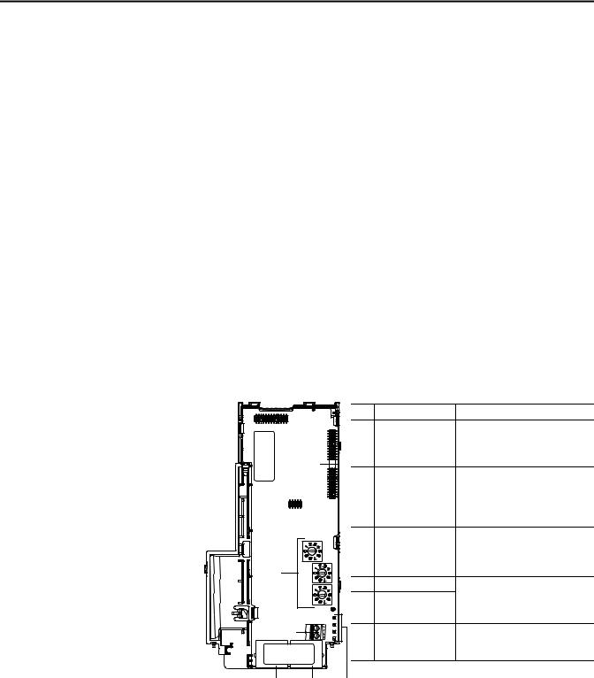
Components of the Dual-Port EtherNet/IP Adapter
25-COMM-E2P
|
|
Item |
Part |
Description |
|
|
|
Communication |
A 40-pin, double-row shrouded female |
|
|
|
card-Drive header |
header. An interface connector is used to |
|
|
|
|
connect this header to a header on the |
|
|
|
|
drive. |
|
|
Node Address switches |
Sets the network node address of the |
|
|
|
|
||
|
|
|
|
adapter when not using: |
|
|
|
|
• A BOOTP or DHCP server |
|
|
|
|
• Adapter parameters |
|
|
|
|
See Setting the Node Address on page 16. |
|
|
|
CS1/CS2 terminals |
Provides a clean ground for the |
|
|
|
|
communication bus cable shields. |
|
|
|
|
CS1 or CS2 should be connected to a clean |
|
|
|
|
ground or PE ground on the drive. |
|
|
ENET1 Network port |
An RJ-45 connector for the Ethernet |
|
|
|
|
||
|
|
|
ENET2 Network port |
cable. It is CAT-5 compliant to ensure |
|
|
reliable data transfer on 100Base-Tx |
||
|
|
|
|
|
|
|
|
|
Ethernet connections. |
|
|
|
Status indicators |
Four LEDs that indicate the status of the |
|
|
|
|
connected drive, adapter and network. |
|
|
|
|
See Troubleshooting on page 115. |
|
|
|
|
|
Rockwell Automation Publication 520COM-UM003A-EN-E - June 2013 |
9 |

Chapter 1 |
Getting Started |
|
|
Features
Understanding Parameter
Types
The features of the Dual-port EtherNet/IP adapter include:
•Industrial Ethernet switch, and ENET1 and ENET2 network ports that provide connections for EtherNet/IP star, linear, or device-level ring (DLR) network topologies.
•Switches to set a network node address before applying power to the drive—or you can disable the switches and use a BOOTP server, a Dynamic Host Configuration Protocol (DHCP) server, or adapter parameters to configure the IP address.
•Compatibility with various configuration tools to configure the adapter and host drive. The tools include the PowerFlex 4/40-class HIM (Human Interface Module 22-HIM-A3 or 22-HIM-C2S), and drive-configuration software such as RSLogix 5000 (version 17 or greater), Logix Designer (version 21 or greater), and Connected Components Workbench (version 3 or greater).
•Status indicators that report the status of the adapter and network communications.
•Parameter-configured 16-bit Datalinks in the I/O to meet application requirements (four Datalinks to write data from the network to the drive, and four Datalinks to read data to the network from the drive).
•Explicit Messaging support.
•Master-Slave hierarchy that can be configured to transmit data to and from a controller on the network.
•Multi-drive mode which allows up to five drives to share a single EtherNet/IP node.
•User-defined fault actions to determine how the adapter and its host PowerFlex 520-series drive respond to:
–I/O messaging communication disruptions (Comm Flt Action)
–Controllers in idle mode (Idle Flt Action)
•Automatic Device Configuration (ADC) is an RSLogix 5000 (version 20 or greater) and Logix Designer (version 21 or greater) software feature that supports the automatic download of configuration data upon the Logix controller establishing an EtherNet/IP network connection to a PowerFlex 520-series drive and its associated peripherals.
This manual references two types of parameters:
•Device parameters are used to configure the adapter to operate on the network. These parameters reside on the adapter.
•Host parameters are used to configure the drive, including the datalink configuration for the datalinks used by the adapter. These parameters reside on the drive.
10 |
Rockwell Automation Publication 520COM-UM003A-EN-E - June 2013 |
Getting Started |
Chapter 1 |
|
|
Compatible Products
You can view adapter Device parameters and Host parameters with any of the following drive configuration tools:
•PowerFlex 4-class HIM (22-HIM-A3 or 22-HIM-C2S)
•Connected Components Workbench software – click the tab for the adapter at the bottom of the window, and click the Parameters icon in the tool bar.
At the time of publication, the adapter is compatible with Allen-Bradley PowerFlex 525 and PowerFlex 523 drives.
Required Equipment |
Equipment Shipped with the Drive |
When you unpack the adapter, verify that the package includes:
One PowerFlex 520-series Dual-port EtherNet/IP communications adapter (25-COMM-E2P) (installed in a PowerFlex 520-series drive control module back cover)
Two interface connectors (for connecting the Communication card-Drive header to the header on the drive)
One PowerFlex 520-series Communication Adapters Installation Instructions, publication 520COM-IN001
User-Supplied Equipment
The adapter parameters can be configured using the drive keypad interface (see Using the Drive Keypad Interface to Access Parameters on page 25). In addition, you must supply:
Ethernet cable (see the EtherNet/IP Media Planning and Installation Manual, ODVA publication 148 available on the ODVA web site at http://odva.org/Home/ODVATECHNOLOGIES/EtherNetIP/EtherNetIPLibrary/tabid/76/Default.aspx for details)
Ethernet switch (see the Ethernet Design Considerations Reference Manual, Rockwell Automation publication ENET-RM002 for details)
Optional configuration tool, such as:
–PowerFlex 22-HIM-A3/-C2S HIM
–DHCP/BOOTP Utilities
Controller configuration software, such as:
–RSLinx Classic (version 2.50 or later)
–RSLogix 5000 (version 17 or greater) or Logix Designer (version 21 or greater) when using drive-specific Add-On Profile (AOP)
–Connected Components Workbench (version 3 or greater)
A PC connection to the EtherNet/IP network
Rockwell Automation Publication 520COM-UM003A-EN-E - June 2013 |
11 |
Chapter 1 |
Getting Started |
|
|
Safety Precautions
Please read the following safety precautions carefully.
ATTENTION: Risk of injury or death exists. The PowerFlex drive may contain high voltages that can cause injury or death. Remove all power from the PowerFlex drive, and then verify power has been removed before installing or removing an adapter.
ATTENTION: Risk of injury or equipment damage exists. Only personnel familiar with drive and power products and the associated machinery should plan or implement the installation, start up, configuration, and subsequent maintenance of the drive using this Dual-port EtherNet/IP adapter. Failure to comply may result in injury and/or equipment damage.
ATTENTION: Risk of equipment damage exists. The adapter contains ESD (Electrostatic Discharge) sensitive parts that can be damaged if you do not follow ESD control procedures. Static control precautions are required when handling the adapter. If you are unfamiliar with static control procedures, see Guarding Against Electrostatic Damage, publication 8000-4.5.2.
ATTENTION: Risk of injury or equipment damage exists. If the adapter is transmitting control I/O to the drive, the drive may fault when you reset the adapter. Determine how your drive will respond before resetting the adapter.
ATTENTION: Risk of injury or equipment damage exists. Device parameters 23 [Comm Flt Action] and 24 [Idle Flt Action] let you determine the action of the adapter and drive if I/O communication is disrupted, the controller is idle, or explicit messaging for drive control is disrupted. By default, these parameters fault the drive. You may configure these parameters so that the drive continues to run, however, precautions should be taken to ensure that the settings of these parameters do not create a risk of injury or equipment damage. When commissioning the drive, verify that your system responds correctly to various situations (for example, a disconnected cable or a controller in idle state).
ATTENTION: Risk of injury or equipment damage exists. When a system is configured for the first time, there may be unintended or incorrect machine motion. Disconnect the motor from the machine or process during initial system testing.
ATTENTION: Risk of injury or equipment damage exists. The examples in this publication are intended solely for purposes of example. There are many variables and requirements with any application. Rockwell Automation, Inc. does not assume responsibility or liability (to include intellectual property liability) for actual use of the examples shown in this publication.
12 |
Rockwell Automation Publication 520COM-UM003A-EN-E - June 2013 |

Getting Started |
Chapter 1 |
|
|
Quick Start
This section is provided to help experienced users quickly start using the adapter. If you are unsure how to complete a step, refer to the referenced chapter.
Step |
Action |
See... |
|
|
|
1 |
Review the safety precautions for the adapter. |
Throughout this manual |
|
|
|
2 |
Verify that the PowerFlex drive is properly installed. |
PowerFlex 525 |
|
|
Adjustable Frequency AC |
|
|
Drive User Manual, |
|
|
publication 520-UM001 |
3 |
Commission the adapter. |
Chapter 2, |
|
Set the adapter IP address. When using the adapter node address switches, set the IP |
Installing the Adapter |
|
address now and proceed with step 4. When using a DHCP or BOOTP server, or adapter |
|
|
parameters instead to set the IP address, proceed with step 4. |
|
4 |
Install the adapter. |
PowerFlex 520-Series |
|
Verify that the PowerFlex drive is not powered. Then, connect the adapter to the drive |
Communication Adapters |
|
using the interface connector (included with adapter). |
Installation Instructions, |
|
|
publication 520COM- |
|
|
IN001 and |
|
|
Chapter 2, |
|
|
Installing the Adapter |
5 |
Connect the adapter to the EtherNet/IP network. |
Chapter 2, |
|
Verify that the PowerFlex drive is not powered. Then, connect the adapter to the |
Installing the Adapter |
|
network using an Ethernet cable. |
|
6 |
Apply power to the drive. |
|
|
a. Replace the control module cover. |
|
|
b. The adapter receives power from the drive. Apply power to the drive. The status |
|
|
indicators should be green. If they flash red, there is a problem. See |
|
|
Troubleshooting on page 115. |
|
|
c. Configure and verify key drive parameters. |
|
7 |
Configure the adapter for your application. |
Chapter 3, |
|
Set adapter parameters for the following functions as required by your application: |
Configuring the Adapter |
|
– IP address, subnet mask, and gateway address (only when not using adapter |
|
|
node address switches) |
|
|
– Data rate |
|
|
– I/O configuration |
|
|
– Master-Slave hierarchy |
|
|
– Fault actions |
|
8 |
Configure the controller to communicate with the adapter. |
Chapter 4, |
|
Use a controller configuration tool such as RSLogix 5000 or Logix Designer to configure |
Configuring the I/O |
|
the master on the EtherNet/IP network to recognize the adapter and drive. |
|
9 |
Create a ladder logic program. |
Chapter 5, |
|
Use a controller configuration tool such as RSLogix 5000 or Logix Designer to create a |
Using the I/O |
|
ladder logic program that enables you to: |
Chapter 6, |
|
– Control the adapter and connected drive using I/O. |
Using Explicit Messaging |
|
– Monitor or configure the drive using Explicit messages. |
|
Rockwell Automation Publication 520COM-UM003A-EN-E - June 2013 |
13 |

Chapter 1 |
Getting Started |
|
|
Notes:
14 |
Rockwell Automation Publication 520COM-UM003A-EN-E - June 2013 |

Chapter 2
Installing the Adapter
Preparing for Set-Up
Chapter 2 provides instructions for installing the Dual-port EtherNet/IP adapter in a PowerFlex 520-series drive.
Topic |
Page |
|
|
Preparing for Set-Up |
15 |
|
|
Setting the Node Address |
16 |
|
|
Connecting the Adapter to the Drive |
18 |
|
|
Connecting the Adapter to the Network |
20 |
|
|
Applying Power |
22 |
|
|
Commissioning the Adapter |
24 |
|
|
Before installing the adapter, do the following:
•Make sure the Ethernet switch is the correct type. A “managed” switch that supports IGMP snooping is usually recommended. An “unmanaged” switch can be used instead if RSLogix 5000 software (version 18 or greater) is used and all devices on the network are configured for “unicast” I/O. For more details, see the following documents:
–EtherNet/IP Media Planning and Installation Manual, ODVA publication 148
–EtherNet/IP Network Infrastructure Guidelines, ODVA publication 35
–Ethernet Design Considerations Reference Manual, publication ENET-RM002
•Understand IGMP Snooping/Ethernet Switches
The adapter is a multicast device. In most situations, an IGMP snooping (managed) switch is required. If more than one or two adapters are connected to the switch, a managed switch is required—otherwise the drive may fault on a Net I/O Timeout network loss. The adapter, RSLogix 5000 (version 18 or greater), Logix Designer (version 21 or greater), and a ControlLogix or CompactLogix controller will support unicast. Unicast setup is required when adding the drive to the I/O. When all adapters are set up as unicast devices, then an IGMP snooping (managed) switch is not needed.
Much of EtherNet/IP implicit (I/O) messaging uses IP multicast to distribute I/O control data, which is consistent with the CIP producer/ consumer model. Historically, most switches have treated multicast packets the same as broadcast packets. That is, all multicast packets are retransmitted to all ports.
Rockwell Automation Publication 520COM-UM003A-EN-E - June 2013 |
15 |

Chapter 2 Installing the Adapter
IGMP snooping constrains the flooding of multicast traffic by dynamically configuring switch ports so that multicast traffic is forwarded only to ports associated with a particular IP multicast group.
Switches that support IGMP snooping (managed switches) “learn” which ports have devices that are part of a particular multicast group and only forward the multicast packets to the ports that are part of the multicast group.
Be careful as to what level of support a switch has of IGMP snooping. Some layer 2 switches that support IGMP snooping require a router (which could be a layer 3 switch) to send out IGMP polls to learn what devices are part of the multicast group. Some layer 2 switches can use IGMP snooping without a router sending polls. If your control system is a stand-alone network or is required to continue performing if the router is out of service, make sure the switch you are using supports IGMP snooping without a router being present.
•See Specifications on page 123 for the number of CIP connections supported by the adapter.
•Verify that you have all required equipment. See Required Equipment on page 11.
ATTENTION: Risk of equipment damage exists. The adapter contains ESD (Electrostatic Discharge) sensitive parts that can be damaged if you do not follow ESD control procedures. Static control precautions are required when handling the adapter. If you are unfamiliar with static control procedures, see Guarding Against Electrostatic Damage, publication 8000-4.5.2.
IMPORTANT The adapter has EtherNet/IP embedded switch technology, and ENET1 and ENET2 network ports to connect to a linear or device-level ring (DLR) network in a single subnet.
You cannot use ENET1 and ENET 2 network ports as two network interface cards connected to two different subnets.
Setting the Node Address |
There are four methods for configuring the adapter’s node address: |
|
• Node Address Switches — Use these switches when working on a simple |
|
isolated network (for example, 192.168.1.xxx) that has other products |
|
with switches to set their IP addresses, does not need to be accessed from |
|
outside the network, and you prefer a simplified node addressing method. |
|
The three rotary switches are read when the drive powers up, and represent |
|
three decimal digits from top to bottom (see Setting the Node Address |
|
Switches on page 18). When set to a valid address (001...254), the adapter |
|
will use that value as the lower octet of its IP address (192.168.1.xxx, where |
|
xxx = rotary switch settings), along with a subnet mask of 255.255.255.0, |
|
and a gateway address of 0.0.0.0 when switches are set to 001, or a gateway |
|
address of 192.168.1.1 when switches are set from 002...254. Also, the |
|
setting for Device parameter 04 [Net Addr Sel] is automatically ignored. |
16 |
Rockwell Automation Publication 520COM-UM003A-EN-E - June 2013 |

Installing the Adapter |
Chapter 2 |
|
|
See Setting the Node Address Switches on page 18 and its accompanying table for all possible switch settings and their related descriptions.
IMPORTANT When using the Node Address switches, set the network node address before power is applied because the adapter uses the node address it detects when it first receives power.
•Adapter Parameters — Use adapter parameters when you want more flexibility in setting up the IP address, or need to communicate outside the control network using a gateway. To use parameters as the source for the IP address, the Node Address switches must be set to a value other than 001...254 or 888, and Device parameter 04 [Net Addr Sel] must be set to 1“Parameters”. The IP address, subnet mask, and gateway addresses will then come from the parameters you set. See Using Adapter Parameters on page 31for more information.
IMPORTANT If parameter values are invalid or the adapter was not reset for the values to take effect, the node address is established by using DHCP.
•BOOTP Server — Use BOOTP when you want to configure a temporary IP address, subnet mask, and gateway address for the adapter using a BOOTP server. To use BOOTP as the source for the IP address, the Node Address switches must be set to a value other than 001...254 or 888, and Device parameter 04 [Net Addr Sel] must be set to 2 “BOOTP”.
Note the adapter’s hardware Ethernet Address (MAC) on the adapter’s data nameplate label located on the provided control module back cover, which will be used in Step 7 when configuring the BOOTP server (see Using a BOOTP or DHCP Server on page 28 for details).
•DHCP (Dynamic Host Configuration Protocol) — Use DHCP, the default, when you want additional flexibility and ease-of-use compared to BOOTP in configuring the IP address, subnet mask, and gateway address for the adapter using a DHCP server. To use DHCP as the source for the IP address, the Node Address switches must be set to a value other than 001…254 or 888, and Device parameter 04 [Net Addr Sel] must be set to 3 “DHCP”.
Note the adapter’s hardware Ethernet Address (MAC) on the adapter’s data nameplate label located on the provided control module back cover, which will be used in Step 7 when configuring the DHCP server (see Using a BOOTP or DHCP Server on page 28 for details).
IMPORTANT Regardless of the method used to set the adapter’s node address, each node on the EtherNet/IP network must have a unique IP address. To change a node address, you must set the new value and then remove and reapply power to (or reset) the drive.
Rockwell Automation Publication 520COM-UM003A-EN-E - June 2013 |
17 |
Chapter 2 Installing the Adapter
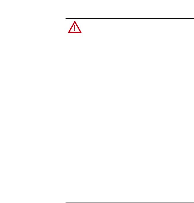
Setting the Node Address Switches
Connecting the Adapter to the Drive
Hundreds
position
Tens position
Ones position
Setting Description
001...254 The adapter will use the Node Address switch settings for the network node address (192.168.1.xxx, where xxx = rotary switch settings). The value stored in Device parameter 04 [Net Addr Sel] is automatically ignored.
888Resets the adapter network node address to factory defaults. Thereafter, the drive must be powered down, the Node Address switches must be set to a correct value (001…254), and then the drive must be powered up again to accept the new address.
Any other |
Disables the Node Address switches, and requires using Device parameter 04 [Net Addr Sel] to select |
||
setting |
the source for the adapter’s network node address: |
||
|
• |
1 |
= Parameters of the adapter |
|
• |
2 |
= BOOTP server |
|
• |
3 |
= DHCP server (Default) |
The Node Address switch settings can be verified by viewing Diagnostic Item number 58 (see page 118 and page 120) with a PowerFlex 22-HIM-A3 or 22- HIM-C2S HIM, or Connected Components Workbench (version 3 or greater) software. Also, you can use Device parameter 05 [Net Addr Src], a read-only parameter, to verify the selected setting for Device parameter 04 [Net Addr Sel].
ATTENTION: Risk of injury or death exists. The PowerFlex drive may contain high voltages that can cause injury or death. Remove all power from the PowerFlex drive, and then verify power has been removed before installing or removing an adapter.
1.Remove power from the drive.
2.Use static control precautions.
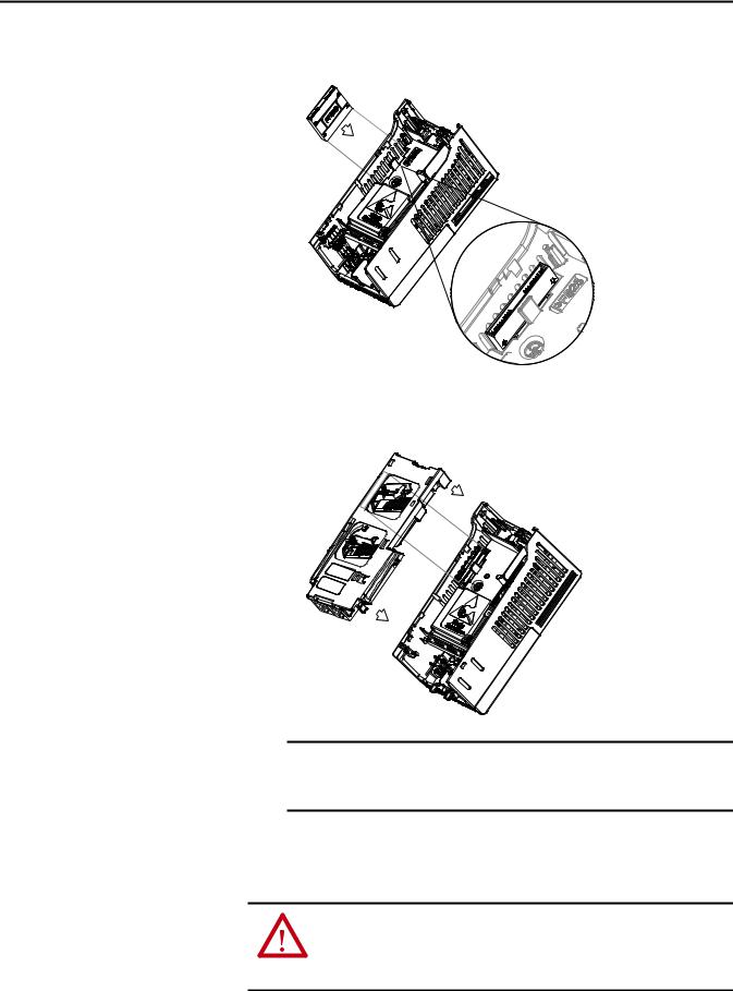
3.Separate the drive’s control module from the power module.
18 |
Rockwell Automation Publication 520COM-UM003A-EN-E - June 2013 |
Installing the Adapter |
Chapter 2 |
|
|
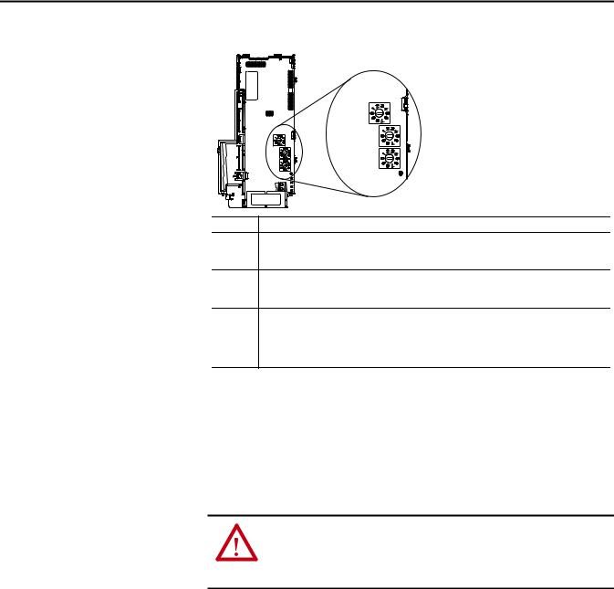
a.Press and hold down the catch on both sides of the frame cover, then pullout and swing upwards to remove (Frames B...E only).
b.Press down and slide out the top cover of the control module to unlock it from the power module.
c.Hold the sides and top of the control module firmly, then pull out to separate it from the power module.
Rockwell Automation Publication 520COM-UM003A-EN-E - June 2013 |
19 |
Chapter 2 Installing the Adapter
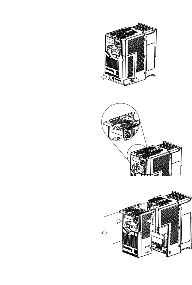
4.Insert the interface connector for the adapter into the header located at the back of the control module.
5.Align the Communication card-Drive header on the adapter with the interface connector. Then, press down firmly around the adapter. The adapter snaps into the back of the control module.
Connecting the Adapter to the Network
IMPORTANT The CS1/CS2 terminals on the adapter provide a clean ground for the communication bus cable shields. You should connect the CS1 or CS2 terminal to a clean ground or PE ground on the drive.
6. Attach the control module to the power module.
ATTENTION: Risk of injury or death exists. The PowerFlex drive may contain high voltages that can cause injury or death. Remove power from the drive, and then verify power has been discharged before connecting the adapter to the network.
20 |
Rockwell Automation Publication 520COM-UM003A-EN-E - June 2013 |
Installing the Adapter |
Chapter 2 |
|
|
1.Remove power from the drive.
2.Use static control precautions.
3.Connect one end of an Ethernet cable to the network.
Examples of different EtherNet/IP network topologies are shown in Connecting the Ethernet Cable in a Star Topology Network on page 21, Connecting the Ethernet Cable in a Linear Topology Network on page 21, and Connecting the Ethernet Cable in a DLR Topology Network on page 22. For information about linear and device-level ring (DLR) topologies, see EtherNet/IP Embedded Switch Technology, publication ENET-AP005.
IMPORTANT The adapter has EtherNet/IP embedded switch technology, and ENET1 and ENET2 network ports to connect to a linear or device-level ring (DLR) network in a single subnet.
You cannot use ENET1 and ENET 2 network ports as two network interface cards connected to two different subnets.
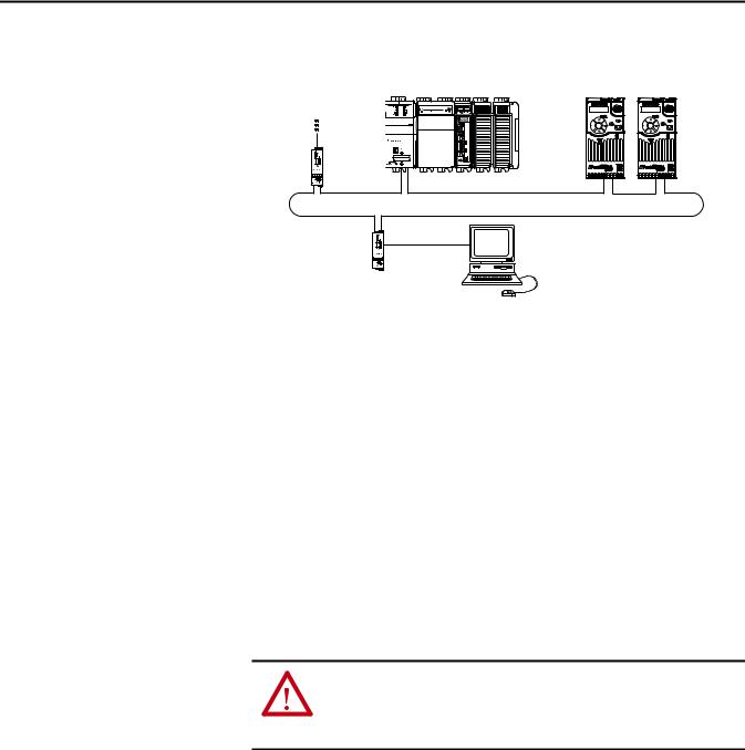
Connecting the Ethernet Cable in a Star Topology Network
1769-L36ERM CompactLogix controller with embedded EtherNet/IP bridge
To other |
|
|
EtherNet/IP |
|
|
networks |
21 |
(Rear) |
|
00:00:BC:2E:69:F6 |
|
|
|
(Front) |
PowerFlex 520-series drives with 25-COMM-E2P adapter(1) (Frame A shown)
Esc |
Sel |
Esc |
Sel |
External |
Computer with |
Ethernet |
Ethernet Connection |
switch |
|
(1) The Ethernet cable may be connected to the adapter’s ENET1 or ENET 2 network port.
Connecting the Ethernet Cable in a Linear Topology Network
1769-L36ERM CompactLogix controller with embedded EtherNet/IP bridge
To other |
|
|
EtherNet/IP |
|
|
networks |
21 |
(Rear) |
|
00:00:BC:2E:69:F6 |
|
|
|
(Front) |
PowerFlex 520-series drives with 25-COMM-E2P adapter(1) (Frame A shown)
Esc |
Sel |
Esc |
Sel |
External |
Computer with |
|
Ethernet Connection |
||
Ethernet |
||
|
||
switch |
|
(1) The adapter’s ENET1 and ENET2 network ports are used.
Rockwell Automation Publication 520COM-UM003A-EN-E - June 2013 |
21 |
Chapter 2 Installing the Adapter
Connecting the Ethernet Cable in a DLR Topology Network
To other |
1769-L36ERM CompactLogix controller |
|
with embedded EtherNet/IP bridge |
||
EtherNet/IP |
|
|
networks |
|
|
1783-ETAP |
00:00:BC:2E:69:F6 |
|
|
1 |
(Front) |
|
2 |
(Rear) |
PowerFlex 520-series drives with 25-COMM-E2P adapter(1) (Frame A shown)
Esc |
Sel |
Esc |
Sel |
1783-ETAP |
Computer with |
Ethernet Connection |
(1) The adapter’s ENET1 and ENET2 network ports are used.
Applying Power
4.Depending on the network topology, do one of the following:
•Star Network Topology—Route the other end of the Ethernet cable from the network through the bottom of the drive, and insert its cable plug into the option module’s ENET1 or ENET2 network port.
•Linear or DLR Network Topology—Route the other end of the Ethernet cable from the network through the bottom of the first drive, and insert its cable plug into the option module ENET1 network port.
To connect to the second drive, attach another Ethernet cable between the first drive’s option module ENET2 network port and the second drive’s option module ENET1 network port.
To connect additional drives, repeat these daisy-chain connections in the same way.
ATTENTION: Risk of equipment damage, injury, or death exists. Unpredictable operation may occur if you fail to verify that parameter settings are compatible with your application. Verify that settings are compatible with your application before applying power to the drive.
Apply power to the drive. The adapter receives its power from the drive.
Startup Status Indication
After power has been applied, the status indicators can be viewed on the front of the drive. When you apply power to the adapter for the first time, the status indicators should be green after an initialization. If the status indicators go red, there is a problem. See Troubleshooting on page 115.
22 |
Rockwell Automation Publication 520COM-UM003A-EN-E - June 2013 |
Installing the Adapter |
Chapter 2 |
|
|
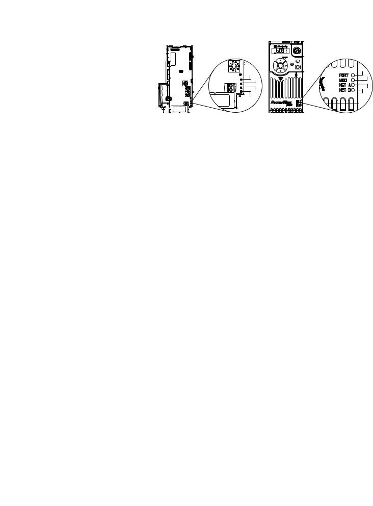
Drive and Adapter Status Indicators
25-COMM-E2P |
PowerFlex 525 Frame A shown |
FWD |
|
ENET LINK |
|
EtherNet/IP |
|
Esc |
Sel |
|
|
|
|
Item |
Status Indicator |
Status(1) |
Description |
|
PORT |
Flashing green |
Normal operation. The adapter is establishing an I/O |
|
|
|
connection to the drive. This status indicator will turn |
|
|
|
steady green or red. |
|
|
Steady green |
Normal operation. The adapter is properly connected and is |
|
|
|
communicating with the drive. |
|
MOD |
Flashing green |
Normal operation. The adapter is operating but is not |
|
|
|
transferring I/O data to a controller. |
|
|
Steady green |
Normal operation. The adapter is operating and transferring |
|
|
|
I/O data to a controller. |
|
NET A |
Flashing green |
Normal operation. The adapter is properly connected but is |
|
|
|
not communicating with any devices on the network. |
|
|
Steady green |
Normal operation. The adapter is properly connected and |
|
|
|
communicating on the network to a controller. |
|
NET B |
Off |
Normal operation. The adapter is properly connected, but is |
|
|
|
idle. |
|
|
Flashing green |
Normal operation. The adapter is properly connected and |
|
|
|
transmitting on the network. |
(1) If all status indicators are off, the adapter is not receiving power. If any other conditions occur, see Troubleshooting on page 85.
For more details on status indicator operation see Understanding the Status Indicators on page 115.
Configuring/Verifying Key Drive Parameters
The PowerFlex 525 drive can be separately configured for the control and Reference functions in various combinations. For example, you could set the drive to have its control come from a peripheral or terminal block with the Reference coming from the network. Or you could set the drive to have its control come from the network with the Reference coming from another peripheral or terminal block. Or you could set the drive to have both its control and Reference come from the network.
Configuring the Host parameters can be done using the drive’s keypad, a HIM, and software such as RSLogix 5000 or Logix Designer, or Connected Components Workbench. In the following example, the drive will receive the Logic Command and Reference from the network.
1.Set the value of Host parameter P046 [Start Source 1] to 4 “Network Opt”.
Rockwell Automation Publication 520COM-UM003A-EN-E - June 2013 |
23 |

Chapter 2 Installing the Adapter
2.Set the value of Host parameter P047 [Speed Reference1] to 4 “Network Opt”.
TIP |
The PowerFlex 525 drive supports up to three control functions and |
|
three Reference functions. |
For more information on how to set different combinations of the control and Reference functions, see the PowerFlex 525 drive user manual,
publication 520-UM001.
Commissioning the Adapter |
To commission the adapter, you must set a unique network node address. See the |
|
Glossary on page 161 for details about IP addresses. When using the Node |
|
Address switches, see Setting the Node Address on page 15 for details. When not |
|
using these switches, a BOOTP or DHCP server, or adapter parameters can be |
|
used to set the node address after connecting the adapter to the network and |
|
applying power to the drive. |
|
By default, the adapter is configured so that you must set the node address using a |
|
DHCP server. For details, see Using a BOOTP or DHCP Server on page 28. To |
|
set the node address using adapter parameters, see Using Adapter Parameters on |
|
page 31. |
|
|
|
IMPORTANT New settings for some adapter parameters (for example, Device parameters 06 |
|
[IP Addr Cfg 1] through 09 [IP Addr Cfg 4]) are recognized only when power |
|
is applied to the adapter or it is reset. After you change parameter settings, |
|
cycle drive power or reset the adapter. |
|
|
24 |
Rockwell Automation Publication 520COM-UM003A-EN-E - June 2013 |

Chapter 3
Configuration Tools
Using the Drive Keypad Interface to Access Parameters
Configuring the Adapter
This chapter provides instructions and information for setting the parameters to configure the Dual-port EtherNet/IP adapter.
Topic |
Page |
|
|
Configuration Tools |
25 |
|
|
Using the Drive Keypad Interface to Access Parameters |
25 |
|
|
Using the PowerFlex 4-Class HIM to Access Parameters |
27 |
|
|
Using a BOOTP or DHCP Server |
28 |
|
|
Using Adapter Parameters |
31 |
|
|
Setting the Data Rate |
32 |
|
|
Using Master-Slave Hierarchy |
33 |
|
|
Setting a Fault Action |
34 |
|
|
Resetting the Adapter |
36 |
|
|
Viewing the Adapter Status Using Parameters |
37 |
|
|
For a list of parameters, see Adapter Parameters on page 125. For definitions of terms in this chapter, see the Glossary on page 161.
The parameters can be configured using the drive keypad interface (see page 25) or a PowerFlex 4-class HIM (Human Interface Module, see page 27).
Software such as RSLogix 5000 (version 17 or greater), Logix Designer (version 21 or greater), and Connected Components Workbench (version 3 or greater) can also be used to access the parameters.
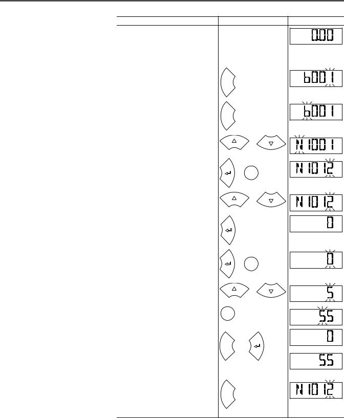
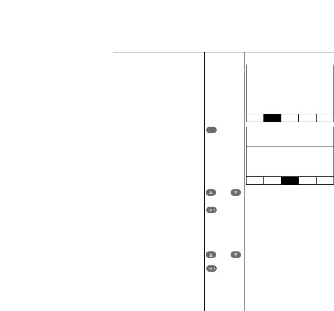
The following is an example of basic integral keypad and display functions. This example provides basic navigation instructions and illustrates how to program a parameter.
IMPORTANT The Dual-port EtherNet/IP adapter Device parameters can be accessed on the drive keypad via the “N” (Network) group. Note that the parameters in the “N” group will appear offset from the Device parameter numbers referenced in this manual by 1000 (decimal) on the LCD display.
Rockwell Automation Publication 520COM-UM003A-EN-E - June 2013 |
25 |
Chapter 3 Configuring the Adapter
Step |
Key(s) |
Example Display |
|
1. |
When power is applied, the last user-selected |
|
|
|
Basic Display Group parameter number is briefly |
|
FWD |
|
|
|
|
|
displayed with flashing characters. The display |
|
HERTZ |
|
|
|
|
|
then defaults to that parameter’s current value |
|
|
|
(Example shows the value of b001 [Output |
|
|
|
Freq] with the drive stopped). |
|
|
2. |
Press Esc to display the Basic Display Group |
|
|
|
parameter number shown on power-up. The |
|
FWD |
|
parameter number will flash. |
Esc |
|
3. |
Press Esc to enter the parameter group list. The |
|
|
|
parameter group letter will flash. |
|
FWD |
|
|
Esc |
|
4. |
Press the Up Arrow or Down Arrow to scroll |
|
or |
|
through the group list (b, P, t, C, L, d, A, f, N, M, |
|
|
|
|
FWD |
|
|
and Gx). |
|
|
5. |
Press Enter or Sel to enter a group. The right |
|
|
|
digit of the last viewed parameter in that group |
or |
FWD |
|
will flash. |
Sel |
|
6. |
Press the Up Arrow or Down Arrow to scroll |
|
or |
|
through the parameter list. |
|
|
|
|
FWD |
|
7. Press Enter to view the value of the parameter.
Or |
FWD |
|
Press Esc to return to the parameter list.
8. |
Press Enter or Sel to enter Program Mode and |
|
|
|
|
edit the value. The right digit will flash and the |
|
or Sel |
FWD |
|
word Program on the LCD display will light up. |
|
PROGRAM |
|
9. |
Press the Up Arrow or Down Arrow to change |
|
or |
|
|
the parameter value. |
|
FWD |
|
|
|
|
||
|
|
|
|
PROGRAM |
10. If desired, press Sel to move from digit to digit |
|
|
|
|
|
or bit to bit. The digit or bit that you can change |
Sel |
|
FWD |
|
will flash. |
|
|
PROGRAM |
11. Press Esc to cancel a change and exit Program |
|
|
|
|
|
Mode. |
|
|
FWD |
|
|
|
|
|
|
Or |
Esc |
or |
or |
|
Press Enter to save a change and exit Program |
|
|
|
|
|
|
|
|
|
Mode. |
|
|
FWD |
|
The digit will stop flashing and the word |
|
|
|
|
Program on the LCD display will turn off. |
|
|
|
12. |
Press Esc to return to the parameter list. |
|
|
|
|
Continue to press Esc to back out of the |
|
|
FWD |
|
programming menu. |
Esc |
|
|
|
If pressing Esc does not change the display, then |
|
|
|
|
b001 [Output Freq] is displayed. Press Enter or |
|
|
|
|
Sel to enter the group list again. |
|
|
|
26 |
Rockwell Automation Publication 520COM-UM003A-EN-E - June 2013 |
Configuring the Adapter |
Chapter 3 |
|
|
Using the PowerFlex 4-Class HIM to Access Parameters
The PowerFlex 4-class HIM can be used to access parameters in the drive (see basic steps shown below). It is recommended that you read through the steps for your HIM before performing the sequence. For additional HIM information, refer to the HIM Quick Reference card, publication 22HIM-QR001.
Step |
Key(s) |
Example Display |
|
1. |
Power up the drive. Then connect the HIM |
|
|
Parameters |
|
||
|
|||
|
to the DSI port of the drive. The Parameters |
|
|
|
tab for the drive will be displayed. |
|
|
|
Groups |
|
|
|
|
||
|
|
|
|
|
|
|
|
|
|
Linear List |
|
|
|
Changed Params |
|
DIAG PARAM DSEL MEM SEL 
2. Press Sel until the DSEL tab is selected. |
|
|
|
|
Sel |
Device Select |
|||
|
||||
|
|
|
|
|
|
|
|
|
|
|
|
|
DSI Devices |
|
|
|
|
|
|
DIAG PARAM DSEL MEM SEL 
3. Select DSI Device in the DSEL tab if it is not |
|
and |
|
|
|
DSI Devices |
|||
already selected using the Up Arrow or |
|
|||
Down Arrow. |
|
|
|
|
|
|
PowerFlex 525 |
||
Press Enter to select DSI Device. |
|
|
||
|
|
25-COMM-E2P |
||
|
|
|||
|
|
|
||
|
|
|
|
|
|
|
|
|
|
4. Press the Up Arrow or Down Arrow to scroll |
|
|
|
|
|
|
and |
DSI Devices |
|||
to 25-COMM-E2P. |
|
||||
|
|
|
|
|
|
Press Enter to reload the HIM to browse |
|
|
|
PowerFlex 525 |
|
|
|
|
|||
only the Communication Adapter (25- |
|
|
|
|
|
|
|
|
25-COMM-E2P |
||
COMM-E2P) parameters. |
|
|
|
|
|
|
|
|
|
|
|
|
|
|
|
|
|
Setting the Adapter Node
Address
To display the Host parameters, repeat steps 1 through 3 and select “PowerFlex 525” at step 3.
When the Node Address switches (see Setting the Node Address Switches on page 18) are set to a value other than 001...254 or 888, Device parameter 04 [Net Addr Sel] determines the source for the adapter node address. By default, the Node Address switches are set to 999 and Device parameter 04 [Net Addr Sel] is set to 3 “DHCP”. This combination selects a DHCP server as the source for the node address. To use a BOOTP or DHCP server to set the node address, see Using a BOOTP or DHCP Server on page 28. To use adapter parameters, see Using Adapter Parameters on page 31.
Rockwell Automation Publication 520COM-UM003A-EN-E - June 2013 |
27 |
Chapter 3 Configuring the Adapter
Using a BOOTP or DHCP Server
By default, the adapter is configured to accept an IP address, subnet mask, and gateway address from a DHCP server. You can select from a variety of DHCP/ BOOTP utilities.
The instructions below use the DHCP/BOOTP Utility (version 2.3 or greater), a free stand-alone program from Rockwell Automation that incorporates the functionality of standard DHCP/BOOTP utilities with a graphical interface. It is available from http://www.ab.com/networks/ethernet/bootp.html. See the Readme file and online Help for directions and more information.
TIP |
If desired, you can disable BOOTP and configure the IP address, subnet mask, |
|
and gateway address using parameters. For details, see Using Adapter |
|
Parameters on page 31. |
Configuring the Adapter Using a DHCP/BOOTP Utility
1.Depending on the type of server (BOOTP or DHCP) being used, set Device parameter 04 [Net Addr Sel] to either 2 “BOOTP” or 3 “DHCP” respectively.
Options 1 “Parameters”
2 “BOOTP”
3“DHCP” (Default)
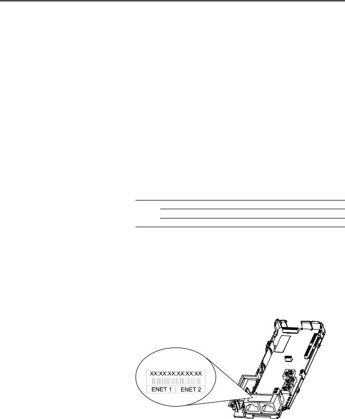
2.Verify and note the adapter’s hardware Ethernet Address (MAC), which will be used in Step 7. There are two ways to do this:
•Use the PowerFlex 525 drive’s keypad or a HIM to access the diagnostic items of the drive. Scroll to items 34 [HW Addr 1] through 39 [HW Addr 6] to view the adapter’s hardware Ethernet Address (MAC). Finally, convert these decimal values to a hex value.
•Locate the adapter’s hardware Ethernet Address (MAC) label on the ENET1/ENET2 ports (provided with the adapter).
Ethernet Address label example
28 |
Rockwell Automation Publication 520COM-UM003A-EN-E - June 2013 |
Configuring the Adapter |
Chapter 3 |
|
|
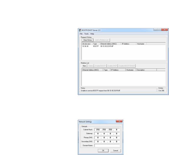
3.On a computer connected to the EtherNet/IP network, start the BOOTP/DHCP software. The BOOTP/DHCP Server window appears.
4.To properly configure devices on your EtherNet/IP network, you must configure settings in the BOOTP/DHCP software to match the network. Select Tools > Network Settings to display the Network Settings window.
5. Edit the following:
Box |
Type |
Subnet Mask(1) |
The subnet mask for the adapter’s network. |
Gateway(1) |
The IP address of the gateway device on the adapter’s network. |
Primary DNS |
The address of the primary DNS server to be used on the local end of the link for |
|
negotiating with remote devices. |
Secondary DNS |
Optional – the address of the secondary DNS server to be used on the local end of the |
|
link for negotiating with remote devices when the primary DNS server is unavailable. |
Domain Name |
The text name corresponding to the numeric IP address that was assigned to the server |
|
that controls the network. |
(1)For definitions of these terms, see the Glossary on page 161.
6.Click OK to apply the settings. Devices on the network issuing BOOTP/ DHCP requests appear in the BOOTP/DHCP Request History list.
Rockwell Automation Publication 520COM-UM003A-EN-E - June 2013 |
29 |
Chapter 3 Configuring the Adapter
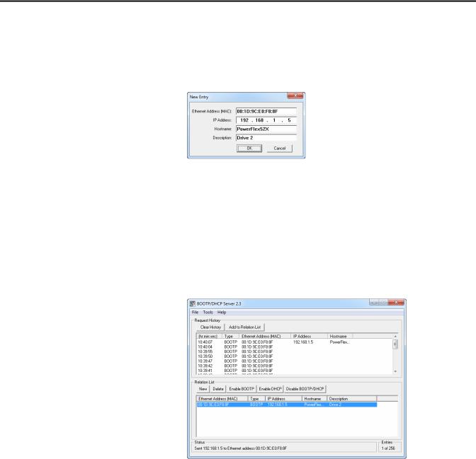
7.In the BOOTP/DHCP Request History list, either double-click the adapter’s Ethernet Address (MAC) noted in Step 2, or click New in the Relation List. The New Entry window appears. In the first case, the Ethernet Address (MAC) is automatically entered. In the latter case, you must manually enter it.
8. Edit the following:
Box |
Type |
IP Address(1) |
A unique IP address for the adapter |
Host Name |
Optional |
|
|
Description |
Optional |
(1)For definitions of these terms, see the Glossary on page 161.
9.Click OK to apply the settings. The adapter appears in the Relation List with the new settings.
10.To assign this configuration to the adapter, select the device in the Relation List and click Disable BOOTP/DHCP. When power is cycled on the drive, the adapter will use the configuration you assigned it and not issue new BOOTP/DHCP requests.
TIP |
To enable BOOTP for an embedded adapter that has had BOOTP |
|
disabled, first select the adapter in the Relation List. Then, depending |
|
on the type of server, click Enable BOOTP or Enable DHCP and, |
|
lastly, reset the adapter or power cycle the drive. |
11. To save the Relation List, select File > Save.
30 |
Rockwell Automation Publication 520COM-UM003A-EN-E - June 2013 |
Loading...