


 Loading...
DeviceLogix System
User Manual
Important User Information
Solid state equipment has operational characteristics differing from those of electromechanical equipment. Safety Guidelines for the Application, Installation and Maintenance of Solid State Controls (publication SGI-1.1 available from your local Rockwell Automation sales office or online at http://www.rockwellautomation.com/literature/) describes some important differences between solid state equipment and hard-wired electromechanical devices. Because of this difference, and also because of the wide variety of uses for solid state equipment, all persons responsible for applying this equipment must satisfy themselves that each intended application of this equipment is acceptable.
In no event will Rockwell Automation, Inc. be responsible or liable for indirect or consequential damages resulting from the use or application of this equipment.
The examples and diagrams in this manual are included solely for illustrative purposes. Because of the many variables and requirements associated with any particular installation, Rockwell Automation, Inc. cannot assume responsibility or liability for actual use based on the examples and diagrams.
No patent liability is assumed by Rockwell Automation, Inc. with respect to use of information, circuits, equipment, or software described in this manual.
Reproduction of the contents of this manual, in whole or in part, without written permission of Rockwell Automation, Inc., is prohibited.
Throughout this manual, when necessary, we use notes to make you aware of safety considerations.
WARNING
Identifies information about practices or circumstances that can cause an explosion in a hazardous environment, which may lead to personal injury or death, property damage, or economic loss.
IMPORTANT Identifies information that is critical for successful application and understanding of the product.
ATTENTION
Identifies information about practices or circumstances that can lead to personal injury or death, property damage, or economic loss. Attentions help you identify a hazard, avoid a hazard, and recognize the consequence
SHOCK HAZARD
Labels may be on or inside the equipment, for example, a drive or motor, to alert people that dangerous voltage may be present.
BURN HAZARD
Labels may be on or inside the equipment, for example, a drive or motor, to alert people that surfaces may reach dangerous temperatures.
Allen-Bradley, Rockwell Automation, Rockwell Software, DeviceLogix, and TechConnect are trademarks of Rockwell Automation, Inc.
Trademarks not belonging to Rockwell Automation are property of their respective companies.

Introduction
Updated Information
Summary of Changes
The release of this document contains new and updated information. To find new and updated information, look for change bars, as shown next to this paragraph.
This document contains the following changes.
Topic |
Page |
|
|
|
|
|
|
Screen format options for download to device |
61, 121 |
|
|
|
|
||
|
|
|
|
PID instruction supported in Function Block Editor and in New |
Chapters 2, 3, 6, and 7 |
|
|
|
|
||
Ladder Editor |
|
|
|
|
|
|
|
ACC binding for Timer/Counter instructions supported in |
Chapters 2 and 6 |
|
|
|
|
||
Function Block Editor and in New Ladder Editor |
|
|
|
|
|
|
|
Macro function supported in Function Block Editor and in New |
Chapters 3 and 7 |
|
|
|
|
||
Ladder Editor |
|
|
|
|
|
|
|
New Ladder Editor introduced |
Chapters 6 and 7 |
|
|
|
|
||
|
|
|
|
Publication RA-UM003B-EN-P - February 2010 |
3 |

Chapter 1 Summary of Changes
Notes:
4 |
Publication RA-UM003B-EN-P - February 2010 |

Table of Contents
Preface
What is DeviceLogix
Functionality?
Navigate the Function Block
Editor Interface
Bind Function Blocks with I/O
Purpose of This Manual. . . . . . . . . . . . . . . . . . . . . . . . . . . . . 9
Who Should Use
This Manual . . . . . . . . . . . . . . . . . . . . . . . . . . . . . . . . . . . . . 9
Related Terms. . . . . . . . . . . . . . . . . . . . . . . . . . . . . . . . . . . . 9
Common Techniques Used in This Manual. . . . . . . . . . . . . . 10
Introduction . . . . . . . . . . . . . . . . . . . . . . . . . . . . . . . . . . . . 11 Inputs and Outputs . . . . . . . . . . . . . . . . . . . . . . . . . . . . 12 Local Function Block Logic . . . . . . . . . . . . . . . . . . . . . . 13 Local Ladder Logic . . . . . . . . . . . . . . . . . . . . . . . . . . . . . 14 DeviceLogix Functionality and Associated Host Software . . . 14 RSNetWorx for DeviceNet Software Operating Modes . . . 15 Drive Tools Software Operating Modes. . . . . . . . . . . . . . 15 DeviceLogix Operating Modes . . . . . . . . . . . . . . . . . . . . 15 Launch the DeviceLogix Editor . . . . . . . . . . . . . . . . . . . . . . 16
What This Chapter Contains . . . . . . . . . . . . . . . . . . . . . . . . 19
Components . . . . . . . . . . . . . . . . . . . . . . . . . . . . . . . . . . . . 19
DeviceLogix Function Block Elements . . . . . . . . . . . . . . . . . 20
I/O Components . . . . . . . . . . . . . . . . . . . . . . . . . . . . . . 21
Function Block Instructions . . . . . . . . . . . . . . . . . . . . . . 23
Enable Line Feature . . . . . . . . . . . . . . . . . . . . . . . . . . . . 50
Configuration Toolbars . . . . . . . . . . . . . . . . . . . . . . . . . . . . 52
Standard Toolbar . . . . . . . . . . . . . . . . . . . . . . . . . . . . . . 52
Tabbed Instruction Toolbars. . . . . . . . . . . . . . . . . . . . . . 53
Macro Block Category Toolbar . . . . . . . . . . . . . . . . . . . . 58
Online Toolbar . . . . . . . . . . . . . . . . . . . . . . . . . . . . . . . 58
Schematic View. . . . . . . . . . . . . . . . . . . . . . . . . . . . . . . . . . 59
Message Pane . . . . . . . . . . . . . . . . . . . . . . . . . . . . . . . . . . . 60
Status Bar . . . . . . . . . . . . . . . . . . . . . . . . . . . . . . . . . . . . . 60
Menus . . . . . . . . . . . . . . . . . . . . . . . . . . . . . . . . . . . . . . . . 61
File Menu . . . . . . . . . . . . . . . . . . . . . . . . . . . . . . . . . . . 61
Edit Menu . . . . . . . . . . . . . . . . . . . . . . . . . . . . . . . . . . . 62
View Menu . . . . . . . . . . . . . . . . . . . . . . . . . . . . . . . . . . 63
Communication Menu . . . . . . . . . . . . . . . . . . . . . . . . . . 64
Tools Menu . . . . . . . . . . . . . . . . . . . . . . . . . . . . . . . . . . 65
Help Menu . . . . . . . . . . . . . . . . . . . . . . . . . . . . . . . . . . 66
What This Chapter Contains . . . . . . . . . . . . . . . . . . . . . . . . 67 Overview of Inputs and Outputs . . . . . . . . . . . . . . . . . . . . . 68 Inputs . . . . . . . . . . . . . . . . . . . . . . . . . . . . . . . . . . . . . . 68 Outputs . . . . . . . . . . . . . . . . . . . . . . . . . . . . . . . . . . . . . 69 Connect I/O points and function block instructions . . . . . . . 69 Determine the status of a connection . . . . . . . . . . . . . . . . . . 70 Negate Data. . . . . . . . . . . . . . . . . . . . . . . . . . . . . . . . . . 70 Set Assume Data Available . . . . . . . . . . . . . . . . . . . . . . . 71 Function Block Properties and Parameters . . . . . . . . . . . 72
Publication RA-UM003B-EN-P - February 2010 |
5 |

Table of Contents
Navigate the Old Ladder Editor
Interface
Create Logic in the Old
DeviceLogix Ladder Editor
Configure the Macro Instruction. . . . . . . . . . . . . . . . . . . . . . 74
Work with the Macro Instruction . . . . . . . . . . . . . . . . . . 74
Edit the Macro Definition and Parameters . . . . . . . . . . . . 80
Offline Operations . . . . . . . . . . . . . . . . . . . . . . . . . . . . . . . 83
Online Operations . . . . . . . . . . . . . . . . . . . . . . . . . . . . . . . 83
Go Online . . . . . . . . . . . . . . . . . . . . . . . . . . . . . . . . . . . 83
Online Animation . . . . . . . . . . . . . . . . . . . . . . . . . . . . . 85
Change Logic. . . . . . . . . . . . . . . . . . . . . . . . . . . . . . . . . 86
Enable and Disable Logic . . . . . . . . . . . . . . . . . . . . . . . . 87
Verify Logic . . . . . . . . . . . . . . . . . . . . . . . . . . . . . . . . . . 87
Compare Logic . . . . . . . . . . . . . . . . . . . . . . . . . . . . . . . 88
Upload and Download Logic . . . . . . . . . . . . . . . . . . . . . 89
Forcing . . . . . . . . . . . . . . . . . . . . . . . . . . . . . . . . . . . . . 91
What This Chapter Contains . . . . . . . . . . . . . . . . . . . . . . . . 95
Components . . . . . . . . . . . . . . . . . . . . . . . . . . . . . . . . . . . . 95
Ladder Elements . . . . . . . . . . . . . . . . . . . . . . . . . . . . . . . . . 96
Rung Element . . . . . . . . . . . . . . . . . . . . . . . . . . . . . . . . 97
Bit Element . . . . . . . . . . . . . . . . . . . . . . . . . . . . . . . . . . 98
Latch Element . . . . . . . . . . . . . . . . . . . . . . . . . . . . . . . . 98
Counter Element . . . . . . . . . . . . . . . . . . . . . . . . . . . . . 100
Timer Element . . . . . . . . . . . . . . . . . . . . . . . . . . . . . . . 102
Configuration Toolbars . . . . . . . . . . . . . . . . . . . . . . . . . . . 106
Standard Toolbar . . . . . . . . . . . . . . . . . . . . . . . . . . . . . 106
Ladder Element Toolbars . . . . . . . . . . . . . . . . . . . . . . . 107
Online Toolbar . . . . . . . . . . . . . . . . . . . . . . . . . . . . . . 109
Ladder Logic View . . . . . . . . . . . . . . . . . . . . . . . . . . . . . . 110
Message Pane . . . . . . . . . . . . . . . . . . . . . . . . . . . . . . . . . . 110
Status Bar . . . . . . . . . . . . . . . . . . . . . . . . . . . . . . . . . . . . 111
Menus . . . . . . . . . . . . . . . . . . . . . . . . . . . . . . . . . . . . . . . 111
File Menu . . . . . . . . . . . . . . . . . . . . . . . . . . . . . . . . . . 112
Edit Menu . . . . . . . . . . . . . . . . . . . . . . . . . . . . . . . . . . 112
View Menu . . . . . . . . . . . . . . . . . . . . . . . . . . . . . . . . . 113
Communication Menu . . . . . . . . . . . . . . . . . . . . . . . . . 114
Tools Menu . . . . . . . . . . . . . . . . . . . . . . . . . . . . . . . . . 115
Help Menu . . . . . . . . . . . . . . . . . . . . . . . . . . . . . . . . . 116
What This Chapter Contains . . . . . . . . . . . . . . . . . . . . . . . 117 Understanding and Working With I/O Tags . . . . . . . . . . . . 117 Online Operations . . . . . . . . . . . . . . . . . . . . . . . . . . . . . . 118 Communication with Devices . . . . . . . . . . . . . . . . . . . . 118 Go On Line . . . . . . . . . . . . . . . . . . . . . . . . . . . . . . . . . 119 Online Animation . . . . . . . . . . . . . . . . . . . . . . . . . . . . 120 Change Logic. . . . . . . . . . . . . . . . . . . . . . . . . . . . . . . . 120 Change the Value of Timers and Counters . . . . . . . . . . 121 Enable and Disable Logic . . . . . . . . . . . . . . . . . . . . . . . 121
6 |
Publication RA-UM003B-EN-P - February 2010 |

Table of Contents
Navigate the New Ladder Editor
Interface
Create Logic in the New Ladder
Editor
Verify Logic . . . . . . . . . . . . . . . . . . . . . . . . . . . . . . . . . 122
Compare Logic . . . . . . . . . . . . . . . . . . . . . . . . . . . . . . 123
Upload and Download Logic . . . . . . . . . . . . . . . . . . . . 123
Forcing . . . . . . . . . . . . . . . . . . . . . . . . . . . . . . . . . . . . 125
Clear Latched Hardware Faults . . . . . . . . . . . . . . . . . . . 126
Recovery Mode . . . . . . . . . . . . . . . . . . . . . . . . . . . . . . 126
What This Chapter Contains . . . . . . . . . . . . . . . . . . . . . . . 127
Components . . . . . . . . . . . . . . . . . . . . . . . . . . . . . . . . . . . 127
Ladder Elements . . . . . . . . . . . . . . . . . . . . . . . . . . . . . . . . 128
Rung Element . . . . . . . . . . . . . . . . . . . . . . . . . . . . . . . 129
Configuration Toolbars . . . . . . . . . . . . . . . . . . . . . . . . . . . 129
Standard Toolbar . . . . . . . . . . . . . . . . . . . . . . . . . . . . . 130
Tabbed Instruction Toolbar . . . . . . . . . . . . . . . . . . . . . 130
Online Toolbar . . . . . . . . . . . . . . . . . . . . . . . . . . . . . . 134
Ladder Logic View . . . . . . . . . . . . . . . . . . . . . . . . . . . . . . 135
Message Pane . . . . . . . . . . . . . . . . . . . . . . . . . . . . . . . . . . 135
Status Bar . . . . . . . . . . . . . . . . . . . . . . . . . . . . . . . . . . . . . 135
Menus . . . . . . . . . . . . . . . . . . . . . . . . . . . . . . . . . . . . . . . 136
File Menu . . . . . . . . . . . . . . . . . . . . . . . . . . . . . . . . . . 137
Edit Menu . . . . . . . . . . . . . . . . . . . . . . . . . . . . . . . . . . 137
View Menu . . . . . . . . . . . . . . . . . . . . . . . . . . . . . . . . . 139
Communications Menu. . . . . . . . . . . . . . . . . . . . . . . . . 140
Tools Menu . . . . . . . . . . . . . . . . . . . . . . . . . . . . . . . . . 141
Help Menu . . . . . . . . . . . . . . . . . . . . . . . . . . . . . . . . . 142
What This Chapter Contains . . . . . . . . . . . . . . . . . . . . . . . 143 About I/O Tags. . . . . . . . . . . . . . . . . . . . . . . . . . . . . . . . . 143 Working with the Tag Database . . . . . . . . . . . . . . . . . . 144 About Screen Format Elements . . . . . . . . . . . . . . . . . . . . . 145 Configure the Macro Instruction. . . . . . . . . . . . . . . . . . . . . 146 Work with the Macro Instruction . . . . . . . . . . . . . . . . . 147 Edit the Macro Definition and Parameters . . . . . . . . . . . 154 Interface Changes Related to Macro Instruction . . . . . . . 158 Online Operations . . . . . . . . . . . . . . . . . . . . . . . . . . . . . . 158 Edit Parameter Values When Online . . . . . . . . . . . . . . . 158 Online Animation . . . . . . . . . . . . . . . . . . . . . . . . . . . . 159 Enable and Disable Logic . . . . . . . . . . . . . . . . . . . . . . . 159 Verify Logic . . . . . . . . . . . . . . . . . . . . . . . . . . . . . . . . . 160 Upload and Download Logic . . . . . . . . . . . . . . . . . . . . 161
Force Inputs and Outputs. . . . . . . . . . . . . . . . . . . . . . . 162
Publication RA-UM003B-EN-P - February 2010 |
7 |

Table of Contents
Register EDS Files and Add
Devices Offline/Online
RSNetWorx for DeviceNet Software and the DeviceLogix Editors
What This Appendix Contains . . . . . . . . . . . . . . . . . . . . . . 165 EDS Files . . . . . . . . . . . . . . . . . . . . . . . . . . . . . . . . . . . . . 165 Unregister EDS files . . . . . . . . . . . . . . . . . . . . . . . . . . . 165 Register EDS Files . . . . . . . . . . . . . . . . . . . . . . . . . . . . 170 Add Devices offline. . . . . . . . . . . . . . . . . . . . . . . . . . . . . . 174 Add Devices online. . . . . . . . . . . . . . . . . . . . . . . . . . . . . . 174
What This Appendix Contains . . . . . . . . . . . . . . . . . . . . . . 177
Access Device Properties. . . . . . . . . . . . . . . . . . . . . . . . . . 177
Check General Information . . . . . . . . . . . . . . . . . . . . . 178
Enter Device Parameters . . . . . . . . . . . . . . . . . . . . . . . 180
Understand Parameters . . . . . . . . . . . . . . . . . . . . . . . . 184
Determine Parameters . . . . . . . . . . . . . . . . . . . . . . . . . 188
Access I/O Data Information . . . . . . . . . . . . . . . . . . . . 195
Access EDS Information . . . . . . . . . . . . . . . . . . . . . . . . 196
Launch the DeviceLogix Editor . . . . . . . . . . . . . . . . . . . 198
8 |
Publication RA-UM003B-EN-P - February 2010 |

Preface
Purpose of This Manual
This manual describes how to install and configure devices using DeviceLogix. It also describes how to navigate and use the old DeviceLogix Ladder Editor, the new DeviceLogix Ladder Editor, and the DeviceLogix Function Block Editor.
See the Following Sections |
See Page |
|
|
Who Should Use This Manual |
9 |
|
|
Related Terms |
9 |
|
|
Common Techniques Used in This Manual |
10 |
|
|
Who Should Use
This Manual
Related Terms
This manual is intended for engineers and technicians who use DeviceLogix to control outputs and manage information locally within devices.
This document assumes that you are familiar with one or more of the following working environments:
•RSNetWorx for DeviceNet software (including the configuration of distributed I/O devices)
•Drive Tools (including DriveExplorer, DriveTools SP, and Drive Add-On Profiles)
Refer to the Related Terms table to become familiar with DeviceLogix.
Related Terms
Name |
Description |
|
|
Download |
The transfer of logic from the software memory to the device. |
|
|
Logic |
Logic consists of function blocks or ladder logic and their interconnnections |
|
that can reside on a DeviceLogix device. |
|
|
MAC ID |
Media Access Control Identifier - An integer identification value assigned to |
|
each node on DeviceNet. This value distinguishes a node among all other |
|
nodes on the same link. |
|
|
NAN |
Not a Number - Value that is typically produced as a the result of an |
|
operation on invalid input operands, especially in floating-point calculations. |
|
|
Upload |
The transfer of logic from the device memory to the software memory. |
|
|
Publication RA-UM003B-EN-P - February 2010 |
9 |

Chapter 1 |
Preface |
|
|
Common Techniques Used
in This Manual
The following conventions are used throughout this manual:
•Bulleted lists provide information, not procedural steps.
•Numbered lists provide sequential steps.
•Pictures of keys and/or dialogs represent the actual keys you press or the dialogs you use.
•Actions you must perform appear in bold and look like the following example: Select Unregister a device.
•A menu item in this format Network > Online identifies the menu item (Network) and the submenu item (Online) after the caret (>).
TIP |
Tips contain helpful information. |
|
|
|
|
10 |
Publication RA-UM003B-EN-P - February 2010 |
Chapter 1
What is DeviceLogix Functionality?
Introduction
DeviceLogix functionality has been added to a number of Rockwell Automation devices to control outputs and manage status information locally within the device.
The configuration of the DeviceLogix functionality is accomplished through the DeviceLogix Editor. The DeviceLogix Editor includes two kinds of logic configuration tools for DeviceLogix devices to meet different configuration preferences:
•Function Block Editor - provides a graphical interface for configuring function blocks to provide local control within DeviceLogix-capable devices.
•Ladder Editor - provides a ladder-style configuration tool for DeviceLogix-capable devices. Beginning with firmware revision 4, two Ladder Editors are available within DeviceLogix. The Old Ladder Editor supports DeviceLogix, firmware revision 3 and earlier. The New Ladder Editor supports DeviceLogix, firmware revision 4.
The DeviceLogix Editor is an applet of RSNetWorx for DeviceNet software and Drive Tools software, and it can be launched directly from those hosts.
With DeviceLogix-capable devices, you can enable a logic operation using the DeviceLogix Editor to provide local control over the device’s operation. A DeviceLogix device consists of:
•a specific number of inputs and/or outputs.
•local logic that determines its behavior.
Publication RA-UM003B-EN-P - February 2010 |
11 |

Chapter 1 What is DeviceLogix Functionality?
Inputs and Outputs
Inputs and outputs can be one of two types.
•Physical - Inputs and outputs realized by physical connections to the device. These are referred to as Discrete/Analog Inputs or Discrete/Analog Outputs.
•Networked - Inputs consumed by the device from the network and outputs produced by the device onto the network.
Input and Output Bits
There are five types of DeviceLogix inputs. Inputs are read from the Electronic Data Sheet (EDS) file or are created dynamically during logic configuration. The inputs that are read from the EDS file cannot be modified. The DeviceLogix inputs are:
•Device Input - A physical input of the device. Device inputs represent the actual inputs, such as sensors and switches, attached to a particular device.
•Network Input - Formerly called the Consumed Network Bit (CNB), network input is data sent from a master that can be used in the device’s logic.
•Device Status - Status inputs indicate the state of the device. For example, if an explicit message connection exists between the device and a master, an input called ‘explicit connection exists’ is set to true and possibly affects the logic the device performs.
•Device Fault - Faults are conditions that report device errors. For example, if a device detects a short circuit on an output, a fault input is set to true and possibly affects the logic the device performs.
12 |
Publication RA-UM003B-EN-P - February 2010 |

What is DeviceLogix Functionality? |
Chapter 1 |
|
|
There are two types of DeviceLogix outputs:
•Device Output - Hardware outputs that are the actual outputs, such as lights and actuators, attached to a particular device. Without DeviceLogix functionality, the master would normally control the outputs via consumed data. In fact, if there is no local logic controlling an output, the master controls the output as it would if DeviceLogix functionality were not running on the device. However, within DeviceLogix functionality, if the local logic controls an output, the master no longer controls the output. The only way the master can affect the state of an output that is under local control is to route requests to the local logic by using network inputs. Some outputs can be under local control while others can still be controlled by the master.
•Network Output - Formerly called Produced Network Bit (PNB), Network outputs report the results of the local logic to a master and are part of the produced data from the device.
Local Function Block Logic
The local logic of a DeviceLogix device consists of function blocks, inputs, outputs, and connections (wires) between them. Function blocks contain connection points (called pins) and perform a specific function. Inputs and outputs also have connection pins and represent the actual hardware devices, networked data, and fault and status bits that are available for use in the local logic.
A connection (wire) between function blocks is defined when an input pin of one function block is bound to an output pin of another function block. A pin can be bound to a:
•pin of another function block.
•physical input/output.
•networked input/output.
•fault or status bit.
•miscellaneous bit.
•block input enable bit and block output enable bit.
Function blocks may also have attributes that influence their function.
Configuring a DeviceLogix device consists of defining or editing the local logic that is present on the device along with the EDS parameters for that device.
Publication RA-UM003B-EN-P - February 2010 |
13 |

Chapter 1 What is DeviceLogix Functionality?
DeviceLogix Functionality
and Associated Host
Software
Local Ladder Logic
The local logic of a DeviceLogix device consists of rung, branch, contact, output coil, and box instructions. A box instruction performs a specific function (such as Timer or Counter). Contact and coil instructions could be hardware data, networked data, and fault and status bits that are available for use in the local logic. Additionally, contact could also refer the output of a box instruction.
The DeviceLogix Editor is a graphical tool for building DeviceLogix functionality in DeviceLogix-enabled products. With the editor, you can create logic, bind logic input and output, verify logic, upload/download logic and enable/disable logic in DeviceLogix-enabled products. When logic is running (in online mode and when logic is enabled), real-time data is animated in the editor and you can also implement forces or perform online parameter modification for some function types.
You configure DeviceLogix features through RSNetWorx for DeviceNet software and Drives Tools software. The DeviceLogix Editor ships as part of RSNetWorx for DeviceNet software, starting with revision 3.0. EDS files that enable DeviceLogix functionality are also shipped with RSNetWorx for DeviceNet software in a separate folder labeled
Additional EDS Files.
For more information on registering EDS files, see Appendix A.
For more information on configuring RSNetWorx for DeviceNet software for use with the DeviceLogix Editors, see Appendix B.
14 |
Publication RA-UM003B-EN-P - February 2010 |

What is DeviceLogix Functionality? |
Chapter 1 |
|
|
RSNetWorx for DeviceNet Software Operating Modes
RSNetWorx for DeviceNet software lets you select online or offline mode, as described below.
•Offline - RSNetWorx for DeviceNet software is not connected to the network.
•Online - RSNetWorx for DeviceNet software is connected to the network and is capable of communicating with devices on the network.
Drive Tools Software Operating Modes
Drive Tools software lets you select online mode, as described below.
•Online - Drive Tools software is connected to the network and is capable of communicating with devices on the network.
DeviceLogix Operating Modes
The mode that RSNetWorx for DeviceNet software is in directly affects the way the DeviceLogix Editor behaves when it is launched. When online with the device, DeviceLogix functionality provides two alternative states: Pending Edits and Animated.
Mode |
|
Description |
|
|
|
Offline |
|
The DeviceLogix Editor does not communicate with the |
|
|
device. If RSNetWorx software is offline, the DeviceLogix |
|
|
Editor is also offline. When offline, you can edit existing |
|
|
DeviceLogix configurations or create new configurations. |
|
|
|
Online |
Pending |
When online with a device, pressing the edit button or |
|
Edits |
selecting Tools > Edit enables Pending Edits. Pending Edits |
|
|
allows a device’s configuration to be edited while online. |
|
|
When your edits are complete, the configuration must be |
|
|
downloaded to the device. |
|
|
|
|
Animated |
When online and animated, DeviceLogix functionality allows |
|
|
a device’s configuration to be monitored in “real time”. Real |
|
|
time includes comms throughput latencies. Depending on the |
|
|
device, you may be able to change presets and accumulated |
|
|
values. |
|
|
|
Publication RA-UM003B-EN-P - February 2010 |
15 |
Chapter 1 What is DeviceLogix Functionality?
Launch the DeviceLogix
Editor
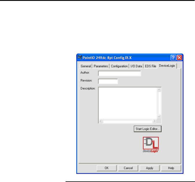
After you configure the properties for your DeviceLogix-enabled device (for more information, see Appendix A), you can launch the DeviceLogix Editor. You see an additional tab in the device properties dialog box for all DeviceLogix-enabled devices. This tab is labeled DeviceLogix. This tab provides access to the start-up window for the DeviceLogix Editor. You have the option to fill in your name, a revision number, and a description of your configuration (all optional fields)..
|
If you are on line and you click on either the Parameters or the |
|
IMPORTANT |
||
DeviceLogix tab, you may be prompted to upload or download |
||
|
||
|
||
|
the device. When you are on line, the dialog checks the |
|
|
configuration in the device and compares it to the current |
|
|
configuration. If the configurations are not the same, you must |
|
|
upload from or download to the device to make the |
|
|
configurations the same before you can make changes. If you |
|
|
need to make changes without uploading or downloading, you |
|
|
can exit the dialog box, go off line and re-enter the dialog box |
|
|
to make the desired changes. |
|
|
|
16 |
Publication RA-UM003B-EN-P - February 2010 |
What is DeviceLogix Functionality? |
Chapter 1 |
|
|
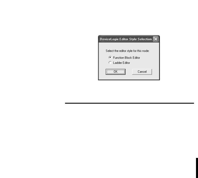
To start the DeviceLogix Editor for a DeviceLogix-enabled device, click Start Logic Editor. On the DeviceLogix Editor Style Selection dialog, you are prompted to select the editor type that you want to launch. After selecting an editor type, click OK.
If the current device does not support one of the editor types, that editor type will be grayed out.
|
If you select an editor type for a particular device and that type |
|
IMPORTANT |
||
is committed to the .dnt file (clicking OK or Apply), that editor |
||
|
||
|
||
|
style is registered. Therefore, you cannot switch to another |
|
|
editor style in that same .dnt file (the next time you launch the |
|
|
DeviceLogix Editor Style Selection dialog, the other editor style |
|
|
is grayed out). If you want to change the editor type (and a |
|
|
device supports both editor types), you must create a new |
|
|
project file, add this device again, and then select the other |
|
|
editor type. |
|
|
|
For more information on the Function Block Editor, refer to Chapters 2 and 3. For more information on the Old Ladder Editor, refer to Chapters 4 and 5. For more information on the New Ladder Editor, refer to Chapters 6 and 7.
Publication RA-UM003B-EN-P - February 2010 |
17 |

Chapter 1 What is DeviceLogix Functionality?
Notes:
18 |
Publication RA-UM003B-EN-P - February 2010 |

Chapter 2
Navigate the Function Block Editor Interface
What This Chapter Contains Read this chapter to learn more information about the Function Block Editor interface. The following table lists what this chapter contains
and where to find specific information.
Topic |
Page |
|
|
Components |
19 |
|
|
DeviceLogix Function Block Elements |
20 |
|
|
I/O Components |
21 |
|
|
Function Block Instructions |
23 |
|
|
Configuration Toolbars |
52 |
|
|
Schematic View |
59 |
|
|
Message Pane |
60 |
|
|
Status Bar |
60 |
|
|
Menus |
61 |
|
|
Components
To help you configure your logic, the Function Block Editor consists of:
•Function Block Elements
•Configuration toolbars
•Schematic view
•Message pane
•Status bar
•Menus
Publication RA-UM003B-EN-P - February 2010 |
19 |

Chapter 2 Navigate the Function Block Editor Interface
Menus
|
|
Tabbed Instruction |
|
Standard toolbar |
|||
toolbar |
|||
|
|
||
Online toolbar |
|
||
Schematic view |
Function block |
||
elements |
|||
Status bar
Message pane
DeviceLogix Function
Block Elements
Function Block elements consist of:
•I/O components: the input and output source of the product, or I/O information from the network
•Function block instructions: all types of DeviceLogix instructions. An instruction’s I/O path needs to be bound with I/O components or the inputs and outputs of another instruction.
• Text comments
20 |
Publication RA-UM003B-EN-P - February 2010 |
Navigate the Function Block Editor Interface |
Chapter 2 |
|
|
I/O Components
In the following sections, we will briefly describe each of the I/O components and include their graphic from the Function Block Editor.
You can drag each of these I/O components from the instruction toolbar, or click the icon and have it added into the current schematic, or select Edit > Add Element to add the I/O component. Each newly added I/O component does not have a binding name; you can click it to display a drop down list related to this component type, and then select the one you needed.
Digital Input Point (DIP)
The following kinds of digital inputs are supported:
•physical local Boolean input point
•local Boolean fault status
•network Boolean input point
•local Boolean miscellaneous point
Digital Output Point (DOP)
The following kinds of digital outputs are supported:
•physical local Boolean output point
•network Boolean output point
Publication RA-UM003B-EN-P - February 2010 |
21 |
Chapter 2 Navigate the Function Block Editor Interface
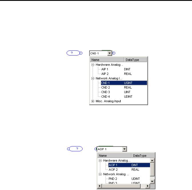
Analog Input Point (AIP)
The following kinds of analog inputs are supported:
•physical local analog input point
•network analog input point
•local analog miscellaneous point
Analog Output Point (AOP)
The following kinds of analog outputs are supported:
•physical local analog output point
•network analog output point
22 |
Publication RA-UM003B-EN-P - February 2010 |

Navigate the Function Block Editor Interface |
Chapter 2 |
|
|
Function Block Instructions
The DeviceLogix Function Block Editor has several categories of function block types:
•Process
•Filter
•Select/Limit
•Statistical
•Timer/Counter
•Compare
•Compute/Math
•Move/Logical
•Macro Block
Each function block type has the following tabs on its property pages:
•General tab - displays general information about this function block instruction. You can also select the function data type (if available) and input a comment for this block. Once any changes have been applied, a sequence number is allocated for this block.
•Parameter tab - Lists all of the parameters available for this function block type. Preset data can be entered in all editable fields. Once logic runs, the real-time value will be updated in the Value column. Note the read-only data is grayed out and cannot be edited.
Process Category
The Process category includes the following instruction types:
•Alarm
•Timing Diagnosis
•PID
Publication RA-UM003B-EN-P - February 2010 |
23 |

Chapter 2 Navigate the Function Block Editor Interface
Alarm
The Alarm function block initiates an alert based on the comparison between the input value and the threshold. The output of the DeviceLogix Alarm function block contains these alerts.
•High-High alarm
•High alarm
•Low alarm
•Low-Low alarm
The details of the Alarm function block are outlined in the table.
Condition |
Output |
Fault State |
|
|
|
INPUT > HHLimit (including the case when |
0x000C |
0 |
HLimit==HHLimit) |
|
|
|
|
|
HLimit < INPUT < HHLimit |
0x0004 |
0 |
|
|
|
LLimit < INPUT < HLimit |
0x0000 |
0 |
|
|
|
LLLimit < INPUT < LLimit |
0x0002 |
0 |
|
|
|
INPUT < LLLimit (including the case when |
0x0003 |
0 |
LLimit==LLLimit) |
|
|
|
|
|
INPUT is NAN* |
Keep the output |
2 |
|
unchanged |
|
|
|
|
INPUT is positive infinity |
0x000C |
2 |
|
|
|
INPUT is negative infinity |
0x0003 |
2 |
|
|
|
Input value from binding source is out of the |
Keep the output |
1 |
object's range |
unchanged |
|
|
|
|
*The condition is only possible when Operation Data Type is REAL.
The valid parameter range is shown below:
Parameters |
Data Range |
|
|
HHLimit |
-2147483648 ~ 2147483647 (DINT) |
|
-3.402823466e+38F ~ 3.402823466e+38F (REAL) |
|
|
HLimit |
-2147483648 ~ 2147483647 (DINT) |
|
-3.402823466e+38F ~ 3.402823466e+38F (REAL) |
|
|
LLimit |
-2147483648 ~ 2147483647 (DINT) |
|
-3.402823466e+38F ~ 3.402823466e+38F (REAL) |
|
|
LLLimit |
-2147483648 ~ 2147483647 (DINT) |
|
-3.402823466e+38F ~ 3.402823466e+38F (REAL) |
|
|
Note: HHLimit >=HLimit >=LLimit >=LLimit
24 |
Publication RA-UM003B-EN-P - February 2010 |
Navigate the Function Block Editor Interface |
Chapter 2 |
|
|
|
When data values are large, switching between REAL and DINT |
|
IMPORTANT |
||
data types may cause a minimal loss of accuracy. For example, |
||
|
||
|
||
|
a value of 99999999 DINT will be rounded up to 100000000 |
|
|
REAL when you switch to a REAL data type and then back to a |
|
|
DINT data type. |
|
|
|
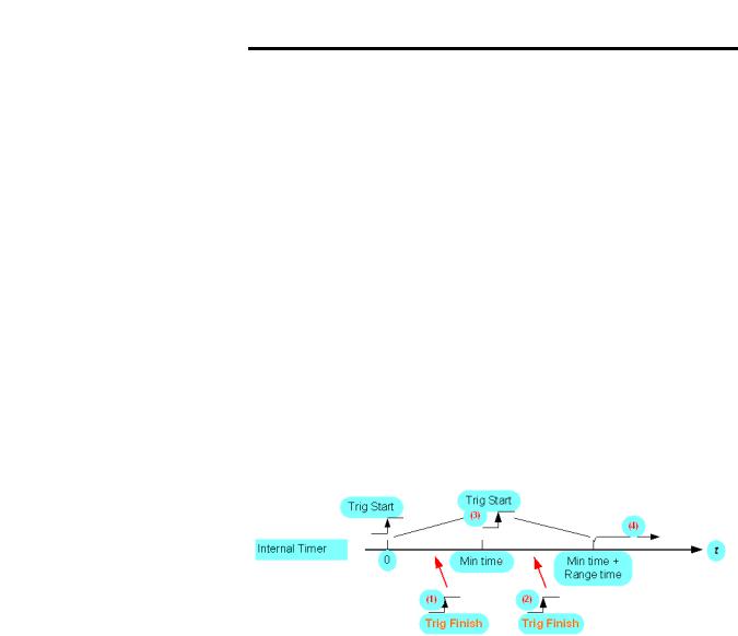
Timing Diagnosis
The DeviceLogix Timing Diagnosis function block object determines whether the occurrence of the expected event is within the preset timing interval.
The following is an operation example:
The rising edge of the Trig Start input indicates the occurrence of a Trig Start event. The rising edge of the Trig Finish input indicates the occurrence of a Trig Finish event.
When the Trig Start event occurs, the Timing Diagnosis function block is started. The internal timer starts timing from 0 as shown below. Meanwhile, the function block reports the triggered status as the output.
The events that occur in the illustration are as follows.
•If the Trig Finish event occurs before the Minimum Time, that is, at the time slot (1), then the function block returns an early finish status. If the occurrence of the Trig Finish event is within the range of Min time and Min time + Range time, as shown in time slot (2), then the Trig Finish event happens within the expected timing slot. Therefore, a normal finish status is returned. If no Trig Finish event occurs at the interval 0 and Min time + Range time, then the Late Finish status is returned, as shown in the time slot (4).
•Within the time interval 0 and Min time + Range time, if the Trig Start event occurs again, that is as shown in the time slot (3), then the Retrigger status is reported as the function block output.
Publication RA-UM003B-EN-P - February 2010 |
25 |
Chapter 2 Navigate the Function Block Editor Interface
•Once the Trig Finish event occurs, or if a Retrigger event is detected, or the Late Finish status is reported, the function block stops operation, and the internal timer stops timing. The function requires a reset event to perform another operation.
•In all cases, the Reset signal overrides all other function block functionality. If the Reset Binding attribute is not supported or it is not bound, the function block behaves as if it is tied low.
•All input edges that occur during reset are ignored.
•The Elapsed Time attribute should be clear at the time that the Trig Start event triggers the function block.
Parameters |
Data Range |
|
|
MinTime |
0 ~ 65535 |
|
|
RangeTime |
0 ~ 65535 |
|
|
ElapsedTime |
0 ~ 65535 |
|
|
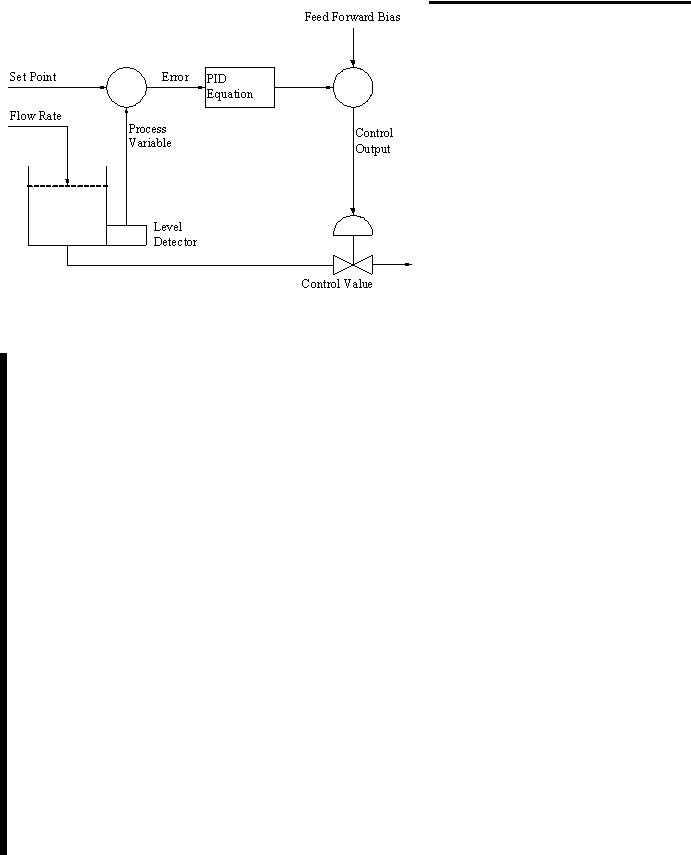
PID
Use the PID function block to control a closed single analog loop.
The PID function block operates only in the timed mode. In this mode, the function block is calculated and updates its output periodically at a user-selectable rate. PID closed loop control holds a process variable at a desired set point. A flow rate/fluid level example is shown in the following figure.
Σ |
Σ |
26 |
Publication RA-UM003B-EN-P - February 2010 |
Navigate the Function Block Editor Interface |
Chapter 2 |
|
|
The PID equation controls the process by sending an output to the actuator device. The greater the error between the setpoint and process variable input, the greater the output will be. An additional value (feedforward or bias) can be added to the control output as an offset. The PID result (control variable) drives the process variable toward the setpoint.
The PID function block monitors and controls the process loop for analog process parameters such as pressure, temperature, flow rate, and fluid level. Features of the PID function block include:
•PID equations expressed in Dependent Gains (ISA standard)
•Input scaling in engineering units
•Zero-crossing deadband
•Derivative term acts on PV
•Direct or reverse acting control
•Output alarms
•Output limiting with anti-reset windup
•Manual mode (with bumpless transfer)
•Feedforward or output biasing
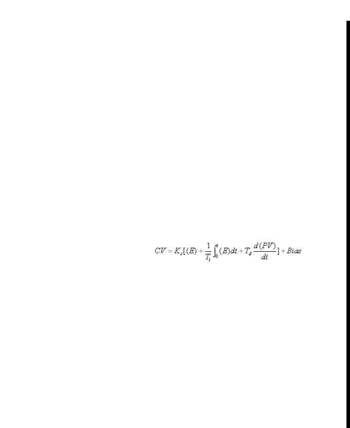
The PID function block uses the following equation with dependent gains:
Where:
Kc is Control Gain
Ti is Reset Term
Td is Rate Term
SP is Set Point
PV is Process Variable
E is (SP-PV) or (PV-SP)
CV is Output Control Variable
t is Loop Update Time
Publication RA-UM003B-EN-P - February 2010 |
27 |

Chapter 2 Navigate the Function Block Editor Interface
The PID function has Enable In and Process Variable as inputs, and Enable Out and Control Variable as outputs, as described in the following tables.
Input |
Type |
Default |
Description |
|
|
|
|
Enable In |
BOOL |
1 |
Enable In |
|
|
|
|
PV |
REAL |
0.0 |
Process Variable |
|
|
|
|
|
|
|
|
Output |
Type |
Default |
Description |
|
|
|
|
Enable Out |
BOOL |
0 |
Enable Out |
|
|
|
|
CV |
REAL |
0.0 |
Control Variable |
|
|
|
|
The PID function also provides four parameters that you can modify as needed:
•Tuning
•Configuration
•Scaling
•Status
Tuning Parameters
Tuning Parameters allow you to set the PID algorithm parameters.
|
|
Parameter |
Type |
Range |
Default |
Description |
|
|
|||||
|
|
|
|
|
|
|
|
|
Setpoint (SP) |
REAL |
|
0.0 |
Desired control point of the process variable. It |
|
|
|
||||
|
|
|
|
|
|
should be scaled in the engineering unit. |
|
|
|
|
|
|
|
|
|
Set Output % |
REAL |
0.0 ~ 100.0 |
0.0 |
PID output for the manual set output mode. Use |
|
|
|||||
|
|
|
|
|
|
this value to prevent bumps in control when |
|
|
|
|
|
|
switching control mode back to automatic. |
|
|
|
|
|
|
|
|
|
Output Bias % |
REAL |
0.0 ~ 100.0 |
0.0 |
Output bias percentage |
|
|
|||||
|
|
|
|
|
|
|
|
|
Control Gain (Kc) |
REAL |
|
0.0 |
Controller gain |
|
|
|
||||
|
|
|
|
|
|
|
|
|
Reset Time (Ti) |
REAL |
|
0.0 |
Reset time |
|
|
|
||||
|
|
|
|
|
|
|
|
|
Rate Time (Td) |
REAL |
|
0.0 |
Rate time |
|
|
|
||||
|
|
|
|
|
|
|
|
|
Station Mode |
BOOL |
|
0 |
Indicates the station mode: |
|
|
|
||||
|
|
|
|
|
|
• 0 = Manual |
|
|
|
|
|
|
• 1= Automatic |
|
|
|
|
|
|
|
28 |
Publication RA-UM003B-EN-P - February 2010 |

Navigate the Function Block Editor Interface |
Chapter 2 |
|
|
Manual and Automatic Modes
The PID function block automatically provides bumpless transfer from manual mode to auto mode. The PID function block back-calculates the value of the integral accumulation term required to make the CV output track the set output value in manual mode. In this manner, when the loop switches to auto mode, the CV output starts off from the set output value and no "bump" in output value occurs.
Configuration Parameters
Configuration parameters allow you to set control loop features.
Parameter |
Type |
Range |
Default |
Description |
|
|
|
|
|||||
|
|
|
|
|
|
|
Control Action |
BOOL |
|
0 |
Indicates the direction of control: |
|
|
|
|
|
||||
|
|
|
|
• 0 is E=SP-PV |
|
|
|
|
|
|
• 1 is E=PV-SP |
|
|
|
|
|
|
This parameter cannot be configured when the |
|
|
|
|
|
|
DeviceLogix logic is in the Run mode. |
|
|
|
|
|
|
|
|
|
Loop Update Time |
UDINT |
|
0 |
Periodical time interval in microseconds for |
|
|
|
|
|
||||
|
|
|
|
output update. |
|
|
|
|
|
|
This parameter cannot be configured when the |
|
|
|
|
|
|
DeviceLogix logic is in the Run mode. |
|
|
|
|
|
|
|
|
|
CV High Limit % |
REAL |
0.0 ~ 100.0 |
0.0 |
System's maximum allowable value for the |
|
|
|
|
|||||
|
|
|
|
Control Variable. The PID function block does |
|
|
|
|
|
|
not output a CV that exceeds the High Limit. |
|
|
|
|
|
|
|
|
|
CV Low Limit % |
REAL |
0.0 ~ 100.0 |
0.0 |
Sytem's minimum allowable value for the |
|
|
|
|
|||||
|
|
|
|
Control Variable. The PID function block does |
|
|
|
|
|
|
not output a CV less than the Low Limit. |
|
|
|
|
|
|
|
|
|
Deadband Value |
REAL |
|
0.0 |
Error range above and below the setpoint. Enter |
|
|
|
|
|
||||
|
|
|
|
"0" to inhibit the deadband. The deadband has |
|
|
|
|
|
|
the same scaled units as the setpoint. |
|
|
|
|
|
|
|
|
|
Deadband
The adjustable deadband is used to select an error range above and below the setpoint where output does not change as long as the error remains within this range. This deadband controls how closely the process variable matches the set point without changing the output.
Publication RA-UM003B-EN-P - February 2010 |
29 |

Chapter 2 Navigate the Function Block Editor Interface
Zero-crossing is deadband control that lets the function block use the error for computational purposes as the process variable crosses into the deadband until the process variable crosses the setpoint. Once the process variable crosses the setpoint (error crosses zero and changes sign), and as long as the process variable remains in the deadband, the function block considers the error value to be zero. The deadband has the same scaled units as the setpoint.
Output Limit
An output limit (percent of output) can be set on the control output. When the function block detects that the output has reached a limit, the PID function block automatically avoids reset windup by preventing the integral term from accumulating whenever the CV output reaches its maximum or minimum values. The accumulated integral term remains frozen until the CV output drops below its maximum limit or rises above its minimum limit. Normal integral accumulation automatically resumes.
Scaling Parameters
Scaling parameters allow you to set the output scale.
|
|
Parameter |
Type |
Default |
Description |
|
|
||||
|
|
|
|
|
|
|
|
PV Max |
REAL |
0.0 |
Maximum value for the unscaled Process |
|
|
||||
|
|
|
|
|
Variable (PV). |
|
|
|
|
|
This parameter cannot be configured when the |
|
|
|
|
|
DeviceLogix logic is in the Run mode. |
|
|
|
|
|
|
|
|
PV Min |
REAL |
0.0 |
Minimum value for the unscaled Process |
|
|
||||
|
|
|
|
|
Variable (PV). |
|
|
|
|
|
This parameter cannot be configured when the |
|
|
|
|
|
DeviceLogix logic is in the Run mode. |
|
|
|
|
|
|
|
|
EU Max |
REAL |
0.0 |
Maximum engineering unit for the Process |
|
|
||||
|
|
|
|
|
Variable (PV). |
|
|
|
|
|
This parameter cannot be configured when the |
|
|
|
|
|
DeviceLogix logic is in the Run mode. |
|
|
|
|
|
|
|
|
EU Min |
REAL |
0.0 |
Minimum engineering unit for the Process |
|
|
||||
|
|
|
|
|
Variable (PV). |
|
|
|
|
|
This parameter cannot be configured when the |
|
|
|
|
|
DeviceLogix logic is in the Run mode. |
|
|
|
|
|
|
|
|
CV Max (at 100%) |
REAL |
0.0 |
Maximum value for the unscaled Control |
|
|
||||
|
|
|
|
|
Variable (CV). |
|
|
|
|
|
This parameter cannot be configured when the |
|
|
|
|
|
DeviceLogix logic is in the Run mode. |
|
|
|
|
|
|
30 |
Publication RA-UM003B-EN-P - February 2010 |
Loading...