


 Loading...
Allen-Bradley
Thermocouple/
Millivolt Input
Module
(Cat. No. 1794-IT8)
User
Manual
Important User Information
Because of the variety of uses for the products described in this publication, those responsible for the application and use of this control equipment must satisfy themselves that all necessary steps have been taken to assure that each application and use meets all performance and safety requirements, including any applicable laws, regulations, codes and standards.
The illustrations, charts, sample programs and layout examples shown in this guide are intended solely for example. Since there are many variables and requirements associated with any particular installation, Allen-Bradley does not assume responsibility or liability (to include intellectual property liability) for actual use based upon the examples shown in this publication.
Allen-Bradley publication SGI±1.1, ªSafety Guidelines For The Application, Installation and Maintenance of Solid State Controlº (available from your local Allen-Bradley office) describes some important differences between solid-state equipment and electromechanical devices which should be taken into consideration when applying products such as those described in this publication.
Reproduction of the contents of this copyrighted publication, in whole or in part, without written permission of Allen±Bradley Company, Inc. is prohibited.
Throughout this manual we make notes to alert you to possible injury to people or damage to equipment under specific circumstances.
|
ATTENTION: Identifies information about practices |
|
! |
or circumstances that can lead to personal injury or |
|
death, property damage, or economic loss. |
||
|
Attention helps you:
•identify a hazard
•avoid the hazard
•recognize the consequences
Important: Identifies information that is especially important for successful application and understanding of the product.
Important: We recommend you frequently backup your application programs on appropriate storage medium to avoid possible data loss.
DeviceNet, DeviceNetManager, and RediSTATION are trademarks of Allen-Bradley Company, Inc. PLC, PLC±2, PLC±3, and PLC±5 are registered trademarks of Allen-Bradley Company, Inc. Windows is a trademark of Microsoft.
Microsoft is a registered trademark of Microsoft
IBM is a registered trademark of International Business Machines, Incorporated.
All other brand and product names are trademarks or registered trademarks of their respective companies.

u o n
u o n
New Information
Updated Information
The information below summarizes the changes to the company-wide templates since the last release.
The following new information has been added to this manual:
•the ªLº type thermocouple selection has been added for use in some European markets.
Calibration procedures have been revised to eliminate 1 method in order to better control calibration results.
Change Bars
The areas in this manual which are different from previous editions are marked with change bars (as shown to the right of this paragraph) to indicate the addition of new or revised information.
Publication 1794-6.5.7 ± April 1997
soc±ii |
Summary of Changes |
Publication 1794-6.5.7 ± April 1997

Table of Contents
Overview of Flex I/O and your Thermocouple/mV Module
How to Install Your Thermocouple/mV Input Module
Module Programming
Chapter 1
Chapter Objectives . . . . . . . . . . . . . . . . . . . . . . . . . . . . . . . . . . . |
1±1 |
The FLEX I/O System . . . . . . . . . . . . . . . . . . . . . . . . . . . . . . . . . |
1±1 |
How FLEX I/O Analog Modules Communicate with Programmable |
|
Controllers . . . . . . . . . . . . . . . . . . . . . . . . . . . . . . . . . . . . . . . |
1±1 |
Typical Communication Between an Adapter and a Module . . . |
1±2 |
Features of your Modules . . . . . . . . . . . . . . . . . . . . . . . . . . . . . . . |
1±3 |
Chapter Summary . . . . . . . . . . . . . . . . . . . . . . . . . . . . . . . . . . . . |
1±3 |
Chapter 2
. . . . . . . . . . . . . . . . . . . . . . . . . . . . . . . . . . . . . . . . . . . . . . . . . . |
2±1 |
Before You Install Your Input Module . . . . . . . . . . . . . . . . . . . . . . . |
2±1 |
European Union Directive Compliance . . . . . . . . . . . . . . . . . . . . . . |
2±1 |
EMC Directive . . . . . . . . . . . . . . . . . . . . . . . . . . . . . . . . . . . . . |
2±1 |
Low Voltage Directive . . . . . . . . . . . . . . . . . . . . . . . . . . . . . . . . |
2±2 |
Power Requirements . . . . . . . . . . . . . . . . . . . . . . . . . . . . . . . . . . |
2±2 |
Wiring the Terminal Base Units (1794-TB2 and -TB3 shown) . . |
2±3 |
Installing the Module . . . . . . . . . . . . . . . . . . . . . . . . . . . . . . . . . . |
2±4 |
Connecting Wiring for the Thermocouple/mV Module . . . . . . . . . . . |
2±5 |
Example of Millivolt Input Wiring to a 1794-TB3 |
|
Terminal Base Unit . . . . . . . . . . . . . . . . . . . . . . . . . . . . . |
2±7 |
Example 3-wire Thermocouple Wiring to a 1794-TB3T |
|
Temperature Terminal Base Unit . . . . . . . . . . . . . . . . . . . |
2±7 |
Module Indicators . . . . . . . . . . . . . . . . . . . . . . . . . . . . . . . . . . . . |
2±8 |
Chapter Summary . . . . . . . . . . . . . . . . . . . . . . . . . . . . . . . . . . . . |
2±8 |
Chapter 3
Chapter Objectives . . . . . . . . . . . . . . . . . . . . . . . . . . . . . . . . . . . |
3±1 |
Block Transfer Programming . . . . . . . . . . . . . . . . . . . . . . . . . . . . |
3±1 |
Sample programs for FLEX I/O Analog Modules . . . . . . . . . . . . . . . |
3±2 |
PLC-3 Programming . . . . . . . . . . . . . . . . . . . . . . . . . . . . . . . . |
3±2 |
PLC-5 Programming . . . . . . . . . . . . . . . . . . . . . . . . . . . . . . . . |
3±3 |
PLC-2 Programming . . . . . . . . . . . . . . . . . . . . . . . . . . . . . . . . |
3±4 |
Chapter Summary . . . . . . . . . . . . . . . . . . . . . . . . . . . . . . . . . . . . |
3±4 |
Publication 1794-6.5.7
ii |
Table of Contents |
Writing Configuration to and Reading Status from your Module with a Remote I/O Adapter
How Communication Takes Place and I/O Image Table Mapping with the DeviceNet Adapter
Calibrating Your Module
Chapter 4
Chapter Objectives . . . . . . . . . . . . . . . . . . . . . . . . . . . . . . . . . . . |
4±1 |
Configuring Your Thermocouple/mV Module . . . . . . . . . . . . . . . . . |
4±1 |
Range Selection . . . . . . . . . . . . . . . . . . . . . . . . . . . . . . . . . . . . . |
4±2 |
Input Scaling . . . . . . . . . . . . . . . . . . . . . . . . . . . . . . . . . . . . . . . . |
4±2 |
Hardware First Notch Filter . . . . . . . . . . . . . . . . . . . . . . . . . . . . . . |
4±3 |
Throughput in Normal Mode . . . . . . . . . . . . . . . . . . . . . . . . . |
4±3 |
Reading Data From Your Module . . . . . . . . . . . . . . . . . . . . . . . . . |
4±4 |
Mapping Data for the Analog Modules . . . . . . . . . . . . . . . . . . . . . . |
4±4 |
Thermocouple/mV Input Module (1794-IT8) Image Table Mapping |
4±4 |
Thermocouple/mV Input Module (1794-IT8) Read . . . . . . . . . . |
4±4 |
Thermocouple/mV Input Module (1794-IT8) Write . . . . . . . . . . |
4±5 |
Word/Bit Descriptions for the 1794-IT8 Thermocouple/mV |
|
Input Module . . . . . . . . . . . . . . . . . . . . . . . . . . . . . . . . . |
4±5 |
Chapter Summary . . . . . . . . . . . . . . . . . . . . . . . . . . . . . . . . . . . . |
4±7 |
Chapter 5
Chapter Objectives . . . . . . . . . . . . . . . . . . . . . . . . . . . . . . . . . . . |
5±1 |
About DeviceNet Manager . . . . . . . . . . . . . . . . . . . . . . . . . . . . . . |
5±1 |
Polled I/O Structure . . . . . . . . . . . . . . . . . . . . . . . . . . . . . . . . . . . |
5±1 |
Adapter Input Status Word . . . . . . . . . . . . . . . . . . . . . . . . . . . . |
5±2 |
System Throughput . . . . . . . . . . . . . . . . . . . . . . . . . . . . . . . . . . . |
5±3 |
Mapping Data into the Image Table . . . . . . . . . . . . . . . . . . . . . . . . |
5±3 |
Thermocouple/mV Input Module (1794-IT8) Image Table Mapping |
5±3 |
Thermocouple/mV Input Module (1794-IT8) Read . . . . . . . . . . |
5±3 |
Thermocouple/mV Input Module (1794-IT8) Write . . . . . . . . . . |
5±4 |
Word/Bit Descriptions for the 1794-IT8 Thermocouple/mV |
|
Input Module . . . . . . . . . . . . . . . . . . . . . . . . . . . . . . . . . |
5±4 |
Defaults . . . . . . . . . . . . . . . . . . . . . . . . . . . . . . . . . . . . . . . . . . . |
5±7 |
Chapter 6
Chapter Objective . . . . . . . . . . . . . . . . . . . . . . . . . . . . . . . . . . . . |
6±1 |
General Information . . . . . . . . . . . . . . . . . . . . . . . . . . . . . . . . . . . |
6±1 |
Tools and Equipment . . . . . . . . . . . . . . . . . . . . . . . . . . . . . . . . . . |
6±2 |
Removing Lead Wire or Thermocouple Extension Wire Resistance . |
6±2 |
Method 1 . . . . . . . . . . . . . . . . . . . . . . . . . . . . . . . . . . . . . . . . |
6±2 |
Method 2 . . . . . . . . . . . . . . . . . . . . . . . . . . . . . . . . . . . . . . . . |
6±3 |
Manually Calibrating your Thermocouple/mV Input Module . . . . . . . |
6±4 |
Flow Chart for Calibration Procedure . . . . . . . . . . . . . . . . . . . . . |
6±5 |
Calibration Setups . . . . . . . . . . . . . . . . . . . . . . . . . . . . . . . . . . |
6±6 |
Wiring Connections for the Thermocouple Module . . . . . . . . . . . |
6±6 |
Read/Write Words for Calibration . . . . . . . . . . . . . . . . . . . . . . . |
6±7 |
Offset Calibration . . . . . . . . . . . . . . . . . . . . . . . . . . . . . . . . . . . |
6±7 |
Gain Calibration . . . . . . . . . . . . . . . . . . . . . . . . . . . . . . . . . . . . |
6±8 |
Publication 1794-6.5.7
Table of Contents |
iii |
Specifications
Thermocouple Restrictions (Extracted from NBS Monograph 125 (IPTS±68))
Calibrating Your Thermocouple/mV Module using DeviceNetManager |
|
Software (Cat. No. 1787-MGR) . . . . . . . . . . . . . . . . . . . . . . . . |
6±9 |
Offset Calibration . . . . . . . . . . . . . . . . . . . . . . . . . . . . . . . . . . . |
6±9 |
Gain Calibration . . . . . . . . . . . . . . . . . . . . . . . . . . . . . . . . . . . . |
6±11 |
Appendix A
Specifications . . . . . . . . . . . . . . . . . . . . . . . . . . . . . . . . . . . . . . . |
A±1 |
Derating Curve . . . . . . . . . . . . . . . . . . . . . . . . . . . . . . . . . . . . . . |
A±2 |
Resolution Curves for Thermocouples . . . . . . . . . . . . . . . . . . . . |
A±3 |
Type B Thermocouple . . . . . . . . . . . . . . . . . . . . . . . . . . . . . . . |
A±3 |
Type E Thermocouple . . . . . . . . . . . . . . . . . . . . . . . . . . . . . . . |
A±3 |
Type C Thermocouple . . . . . . . . . . . . . . . . . . . . . . . . . . . . . . . |
A±4 |
Type J Thermocouple . . . . . . . . . . . . . . . . . . . . . . . . . . . . . . . . |
A±4 |
Type K Thermocouple . . . . . . . . . . . . . . . . . . . . . . . . . . . . . . . |
A±5 |
Type R Thermocouple . . . . . . . . . . . . . . . . . . . . . . . . . . . . . . . |
A±5 |
Type S Thermocouple . . . . . . . . . . . . . . . . . . . . . . . . . . . . . . . |
A±6 |
Type T Thermocouple . . . . . . . . . . . . . . . . . . . . . . . . . . . . . . . |
A±6 |
Type N Thermocouple . . . . . . . . . . . . . . . . . . . . . . . . . . . . . . . |
A±7 |
Worst Case Accuracy for the Thermocouple/mV Module . . . . . . . |
A±7 |
Error Due to Open Circuit Current Through Loop Resistance . . . . |
A±8 |
Worst Case Repeatability for the Thermocouple/mV Input Module |
A±8 |
Appendix B
General . . . . . . . . . . . . . . . . . . . . . . . . . . . . . . . . . . . . . . . . . . . |
B±1 |
B (Platinum ± 30% Rhodium vs Platinum ± 6% Rhodium) Type |
|
Thermocouples . . . . . . . . . . . . . . . . . . . . . . . . . . . . . . . . . |
B±1 |
E (Nickel±Chromium vs Copper±Nickel <Constantan*>) Type |
|
Thermocouple . . . . . . . . . . . . . . . . . . . . . . . . . . . . . . . . . . |
B±2 |
J (Iron vs Copper±Nickel <Constantan*>) Type Thermocouple . . . |
B±2 |
K (Nickel±Chromium vs Nickel±Aluminum) Type Thermocouple . . |
B±4 |
R (Platinum±13% Rhodium vs Platinum) and |
|
S (Platinum±10% Rhodium vs Platinum) Type Thermocouples |
B±5 |
T (Copper vs Copper±Nickel <Constantan*>) Type Thermocouple |
B±5 |
Publication 1794-6.5.7
iv |
Table of Contents |
Publication 1794-6.5.7

Preface
Using This Manual
Preface Objectives
Audience
Vocabulary
What This Manual
Contains
Read this preface to familiarize yourself with this manual and to learn how to use it properly and efficiently.
We assume that you have previously used an Allen-Bradley programmable controller, that you are familiar with its features, and that you are familiar with the terminology we use. If not, read the user manual for your processor before reading this manual.
In addition, if you are using this module in a DeviceNet system, you must be familiar with:
•DeviceNetManagerTM Software, cat. no. 1787-MGR
•Microsoft WindowsTM
In this manual, we refer to:
•the individual thermocouple/mV module as the ªmodule.º
•the programmable controller as the ªcontrollerº or the ªprocessor.º
The contents of this manual are as follows:
Chapter |
Title |
What's Covered |
|
|
|
|
|
1 |
Overview of Flex I/O and Your |
Describes features, capabilities, and hardware |
|
Thermocouple/mV Module |
components. |
||
|
|||
|
|
|
|
2 |
How to Install Your |
Installation and connecting wiring |
|
Thermocouple/mV Input Module |
|||
|
|
||
|
|
|
|
3 |
Module Programming |
Block transfer programming and programming |
|
examples |
|||
|
|
||
|
|
|
|
|
Writing Configuration to and Reading |
Describes block transfer write and block transfer read |
|
4 |
Status from Your Module with a |
configurations, including complete bit/word descriptions. |
|
|
Remote I/O Adapter |
|
|
|
|
|
|
|
How Communication Takes Place |
Describes communication over the I/O backplane |
|
5 |
and I/O Image Table Mapping with |
between the module and the adapter, and how data is |
|
|
the DeviceNet Adapter |
mapped into the image table. |
|
|
|
|
|
6 |
Calibrating Your Module |
Lists the tools needed, and the methods used to |
|
calibrate the thermocouple input module |
|||
|
|
||
|
|
|
Appendix
|
|
Module specifications, derating curve, resolution curves |
A |
Specifications |
for thermocouples, worst case accuracy and error due |
|
|
to open circuit current. |
|
|
|
B |
Thermocouple Restrictions |
Extracted from NBS Monograph 125 (IPTS±68) |
|
|
|
Publication 1794-6.5.7 ± April 1997
P±2 Using This Manual
Conventions |
We use these conventions in this manual: |
|||||||
|
|
|
|
|
|
|
|
|
|
In this manual, we show: |
Like this: |
||||||
|
|
|
|
|
|
|
|
|
|
that there is more information about a topic |
|
|
|
|
|
|
|
|
|
|
|
|
|
|
|
|
|
|
|
|
|
|
|
|
|
|
in another chapter in this manual |
|
|
|
|
|
|
|
|
|
|
|
|
|
|
|
|
|
|
|
|
|
|
|
|
|
that there is more information about the
topic in another manual
More
For Additional Information
For additional information on FLEX I/O systems and modules, refer to the following documents:
|
|
Catalog |
|
Publications |
|
|
|
|
Description |
|
|
|
|
|
|
Installation |
User |
|
||
|
|
Number |
|
|||
|
|
|
|
|||
|
|
|
|
Instructions |
Manual |
|
|
|
1787-MGR |
DeviceNetManager Software User Manual |
|
1787-6.5.3 |
|
|
|
|
|
|
|
|
|
|
|
Industrial Automation Wiring and Grounding Guidelines |
1770-4.1 |
|
|
|
|
|
|
|
|
|
|
|
1794 |
1794 FLEX I/O Product Data |
1794-2.1 |
|
|
|
|
|
|
|
|
|
|
|
1794-ADN |
DeviceNet Adapter |
1794-5.14 |
1794-6.5.5 |
|
|
|
|
|
|
|
|
|
|
1794-ASB/C |
Remote I/O Adapter |
1794-5.46 |
1794-6.5.9 |
|
|
|
|
|
|
|
|
Summary
This preface gave you information on how to use this manual efficiently. The next chapter introduces you to the remote I/O adapter module.
Publication 1794-6.5.7 ± April 1997
Chapter 1
Chapter Objectives
The FLEX I/O System
Adapter/Power Supply
How FLEX I/O Analog Modules Communicate with Programmable Controllers
Overview of FLEX I/O and your Thermocouple/mV Module
In this chapter, we tell you:
•what the FLEX I/O system is and what it contains
•how FLEX I/O modules communicate with programmable controllers
•the features of your thermocouple module
FLEX I/O is a small, modular I/O system for distributed applications that performs all of the functions of rack-based I/O. The FLEX I/O system contains the following components shown below:
Terminal Base I/O Module
20125
•adapter/power supply ± powers the internal logic for as many as eight I/O modules
•terminal base ± contains a terminal strip to terminate wiring for thermocouple or millivolt inputs.
•I/O module ± contains the bus interface and circuitry needed to perform specific functions related to your application
FLEX I/O thermocouple/mV modules are block transfer modules that interface analog signals with any Allen-Bradley programmable controllers that have block transfer capability. Block transfer programming moves input or output data words between the module's memory and a designated area in the processor data table. Block transfer programming also moves configuration words from the processor data table to module memory.
Publication 1794-6.5.7
1±2 Overview of FLEX I/O and your Thermocouple/mV Module
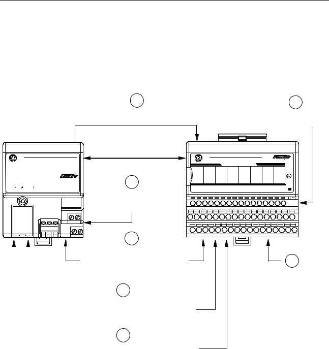
The adapter/power supply transfers data to the module (block transfer write) and from the module (block transfer read) using BTW and BTR instructions in your ladder diagram program. These instructions let the adapter obtain input or output values and status from the module, and let you establish the module's mode of operation. The illustration describes the communication process.
Typical Communication Between an Adapter and a Module
1
The adapter transfers your configuration data to the module using a BTW.
2
External devices transmit analog signals to the module.
Allen-Bradley
ADAPTER |
|
LOCAL |
|
|
|
|||||||
ACTIVE |
|
|
|
FAULT |
|
FAULT |
|
|
|
|||
|
|
|
|
|
|
|
|
|
|
|
|
|
|
|
|
|
|
|
|
|
|
|
|
|
|
|
|
|
|
|
|
|
|
|
|
|
|
|
|
|
|
|
|
|
|
|
|
|
|
|
|
|
|
|
|
|
|
|
|
|
|
|
|
|
24VDC POWER SUPPLY
RIO ADAPTER
1794-ASB
Flexbus
4
Your ladder program instructs the adapter to perform a BTR of the values and stores them in a data table.
5
|
Allen-Bradley |
|
|
1794±IT8 |
|
|
|
THERMOCOUPLE INPUT 8 CHANNEL |
|
|
|
|
|
|
|
|
3 |
INPUT 0 INPUT 1 INPUT 2 INPUT 3 INPUT 4 INPUT 5 INPUT 6 INPUT 7 OK |
|||||
+ ± |
+ ± |
+ ± + ± + ± |
+ |
± |
+ ± + ± |
The adapter and module determine
that the transfer was made without error and input values are within specified range.
6
Your ladder program can use and/or move the data (if valid) before it is written over by the transfer of new data in a subsequent transfer.
7
Your ladder program performs BTWs to the module only when you power it up, or any time you wish to reconfigure the module.
3
The module converts analog signals into binary format and stores these values until the adapter requests their transfer.
Publication 1794-6.5.7
Overview of FLEX I/O and your Thermocouple/mV Module |
1±3 |
Features of your Modules
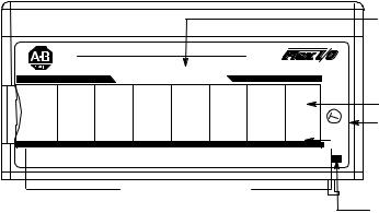
The module label identifies the keyswitch position, wiring and module type. A removable label provides space for writing individual designations per your application.
1794-IT8
|
|
|
|
|
Module Type |
|
Allen-Bradley |
|
|
1794±IT8 |
|
||
|
THERMOCOUPLE INPUT 8 CHANNEL |
|
|
|
||
|
|
|
|
|
Removable Label |
|
|
|
|
|
3 |
Keyswitch |
|
|
|
|
|
OK |
Position |
|
INPUT 0 INPUT 1 |
INPUT 2 INPUT 3 INPUT 4 |
INPUT 5 |
Indicator (#3) |
|||
INPUT 6 INPUT 7 |
||||||
+ ± + ± |
+ ± + ± + ± |
+ |
± |
+ ± + ± |
|
|
|
Input Designators |
|
|
|
||
|
|
|
|
|
Power On Indicator |
|
Chapter Summary
The thermocouple/mV module comes with 2 cold junction compensators. These are designed to mount in designated positions on the temperature terminal base unit (cat. no. 1794-TB3T). Refer to chapter 2 for installation instructions for the cold junction compensator assemblies.
In this chapter, you learned about the FLEX I/O system and the thermocouple module, and how they communicate with programmable controllers.
Publication 1794-6.5.7

1±4 Overview of FLEX I/O and your Thermocouple/mV Module
Publication 1794-6.5.7
Chapter 2
How to Install Your Thermocouple/mV Input Module
Before You Install Your
Input Module
In this chapter, we tell you:
•how to install your module
•how to set the module keyswitch
•how to wire the terminal base
•about the indicators
Before installing your thermocouple/mV module in the I/O chassis:
You need to: |
As described under: |
|
|
|
|
Calculate the power requirements of all |
Power Requirements, page 2-2 |
|
modules in each chassis. |
||
|
||
|
|
|
Position the keyswitch on the terminal base |
Installing the Module, page 2±4 |
|
|
|
|
|
|
ATTENTION: The Thermocouple module does not receive power from the backplane. +24V dc power
! must be applied to your module before installation. If power is not applied, the module position will appear to the adapter as an empty slot in your chassis.
European Union Directive
Compliance
If this product has the CE mark it is approved for installation within the European Union and EEA regions. It has been designed and tested to meet the following directives.
EMC Directive
This product is tested to meet Council Directive 89/336/EEC Electromagnetic Compatibility (EMC) and the following standards, in whole or in part, documented in a technical construction file:
•EN 50081-2EMC ± Generic Emission Standard, Part 2 ± Industrial Environment
•EN 50082-2EMC ± Generic Immunity Standard, Part 2 ± Industrial Environment
This product is intended for use in an industrial environment.
Publication 1794-6.5.7
2±2 |
How to Install Your Thermocouple/mV Input Module |
Power Requirements
Low Voltage Directive
This product is tested to meet Council Directive 73/23/EEC
Low Voltage, by applying the safety requirements of EN 61131±2 Programmable Controllers, Part 2 ± Equipment Requirements and Tests.
For specific information required by EN 61131-2, see the appropriate sections in this publication, as well as the following Allen-Bradley publications:
•Industrial Automation Wiring and Grounding Guidelines For Noise Immunity, publication 1770-4.1
•Guidelines for Handling Lithium Batteries, publication AG-5.4
•Automation Systems Catalog, publication B111
The wiring of the terminal base unit is determined by the current draw through the terminal base. Make certain that the current draw does not exceed 10A.
!
!
ATTENTION: Total current draw through the terminal base unit is limited to 10A. Separate power connections may be necessary.
ATTENTION: Do not daisy chain power or ground from the thermocouple terminal base unit to any ac or dc discrete module terminal base unit.
Publication 1794-6.5.7
How to Install Your Thermocouple/mV Input Module |
2±3 |
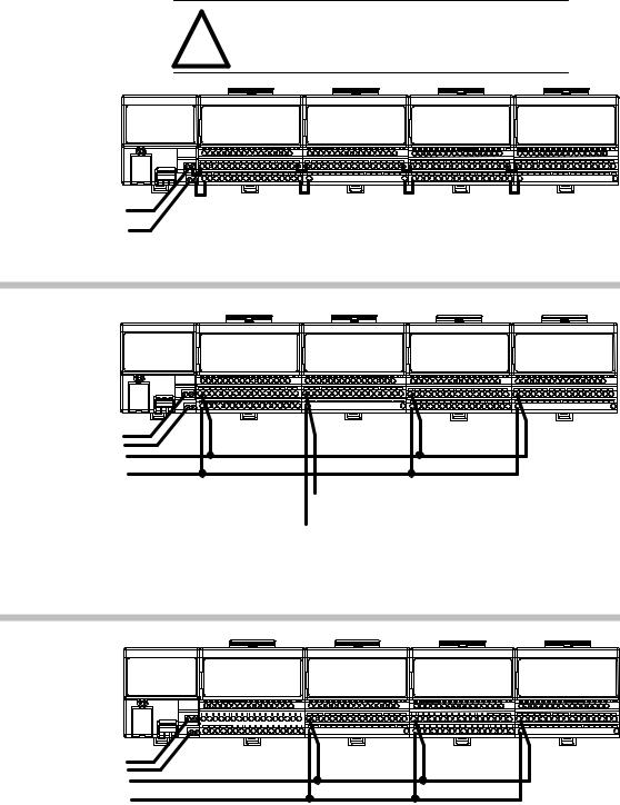
Methods of wiring the terminal base units are shown in the illustration below.
Wiring the Terminal Base Units (1794-TB2 and -TB3 shown)
ATTENTION: Do not daisy chain power or
!ground from the thermocouple terminal base unit to any ac or dc discrete module terminal base unit.
Thermocouple |
Thermocouple |
Thermocouple |
Thermocouple |
or Analog Module |
or Analog Module |
or Analog Module |
or Analog Module |
Daisy-chaining
24V dc |
Note: All modules must be analog modules for this configuration. |
Wiring when total current draw is less than 10A
|
Discrete |
Thermocouple |
Discrete |
Discrete |
Individual |
Module |
or Analog Module |
Module |
Module |
|
|
|
|
24V dc
24V dc or
120V ac
|
|
|
|
Note: Use this configuration if using any |
|
|
|
|
|
24V dc |
|
|
ªnoisyº dc discrete I/O modules in your system. |
|
|
|
|
|
|
Thermocouple module |
wiring separate from discrete wiring. |
|||
Wiring when total current draw is greater than 10A
Combination |
|
|
Discrete |
|
|
Thermocouple |
|
Thermocouple |
|
Thermocouple |
||||||
|
|
|
Module |
|
|
or Analog Module |
or Analog Module |
|
or Analog Module |
|||||||
|
|
|
|
|
|
|
|
|
|
|||||||
|
|
|
|
|
|
|
|
|
|
|
|
|
|
|
|
|
|
|
|
|
|
|
|
|
|
|
|
|
|
|
|
|
|
|
|
|
|
|
|
|
|
|
|
|
|
|
|
|
|
|
|
|
|
|
|
|
|
|
|
|
|
|
|
|
|
|
|
|
|
|
|
|
|
|
|
|
|
|
|
|
|
|
|
|
|
|
|
|
|
|
|
|
|
|
|
|
|
|
|
|
|
24V dc
24V dc
Note: All modules powered by the same power supply must be analog modules for this configuration.
Total current draw through any base unit must not be greater than 10A
Publication 1794-6.5.7
2±4 |
How to Install Your Thermocouple/mV Input Module |
Installing the Module
The thermocouple/mV module mounts on a 1794-TB2, -TB3 or -TB3T terminal base unit.
Important: You must use a 1794-TB3T terminal base unit if you are using the thermocouple/mV module for thermocouple inputs. You can use the 1794-TB2 or -TB3 terminal base for millivolt inputs only.
7
3 |
1 |
|
2
6
4
5
1.Rotate the keyswitch (1) on the terminal base unit (2) clockwise to position 3 as required for the thermocouple/mV module.
2.Make certain the flexbus connector (3) is pushed all the way to the left to connect with the neighboring terminal base/adapter.
You cannot install the module unless the connector is fully extended.
ATTENTION: Remove field-side power before removing or inserting the module. This module is
! designed so you can remove and insert it under backplane power. When you remove or insert a module with field-side power applied, an electrical arc may occur. An electrical arc can cause personal injury or property damage by:
• sending an erroneous signal to your system's field devices causing unintended machine motion
• causing an explosion in a hazardous environment Repeated electrical arcing causes excessive wear to contacts on both the module and its mating connector. Worn contacts may create electrical resistance.
3. Before installing the module, check to make sure that the pins on the bottom of the module are straight so they will align properly with the female connector in the base unit.
4. Position the module (4) with its alignment bar (5) aligned with the groove (6) on the terminal base.
5. Press firmly and evenly to seat the module in the terminal base unit. The module is seated when the latching mechanism (7) is locked into the module.
6. Repeat the above steps to install the next module in its terminal base unit.
Publication 1794-6.5.7
How to Install Your Thermocouple/mV Input Module |
2±5 |
Connecting Wiring for the Thermocouple/mV Module
Thermocouple/mV module wiring is made through the terminal base unit on which the module mounts. The module comes with 2 cold junction compensators for use when using the thermocouple module in the thermocouple mode.
Compatible terminal base unit are:
|
Module |
1794-TB2 |
1794-TB3 |
1794-TB3T1 |
|
|
1794-IT8 |
Yes2 |
Yes2 |
Yes |
|
1 |
The 1794-TB3T terminal base unit contains connections for cold junction |
||||
2 |
compensation for use with thermocouple modules. |
|
|
||
For millivolt inputs only. |
|
|
|
||
|
|
|
|
|
|
|
|
|
|
|
|
|
|
|
|
|
1794-TB2 and 1794-TB3 |
|
|
|
|
|
|
|
|
|
|
|
|
|
|
|
|
|
|
|
|
|
|
|
|
|
|
|
1794-TB3T |
|
|
|
|
|
|
|
|
|
|
|
|
|
|
||||||||||||||||||||||||||
|
|
|
|
|
|
|
|
|
|
|
|
|
|
|
|
|
|
|
|
|
|
|
|
|
|
|
|
|
|
|
|
|
|
|
|
|
|
|
|
|
|
|
|
|
|
|
|
|
|
|
|
|
|
|
|
|
|
|
|
|
|
|
|
|
|
|
|
|
|
|
|
|
|
|
|
|
|
|
|
0 |
1 |
|
2 |
3 |
4 |
5 |
6 |
7 |
8 |
9 |
10 |
|
11 12 13 |
|
14 15 |
|
|
|
|
|
0 ±15 |
0 |
1 |
2 |
|
3 |
|
4 |
|
5 |
6 |
7 |
8 |
|
9 |
10 |
|
11 12 13 |
|
14 15 |
|
|
|
|
|||||||||||||||||||||||||||||||||||
|
|
|
|
|
|
|
|
|
|
|
|
|
|
|
|
|
|
|
|
|
|
|
|
|
|
|
|
|
|
|
|
|
|
|
|
|
A |
A |
|
|
|
|
|
|
|
|
|
|
|
|
|
|
|
|
|
|
|
|
|
|
|
|
|
|
|
|
|
|
|
|
|
|
|
|
|||||
|
|
|
|
|
|
|
|
|
|
|
|
|
|
|
|
|
|
|
|
|
|
|
|
|
|
|
|
|
|
|
|
|
|
|
|
|
|
|
|
|
|
|
|
|
|
|
|
|
|
|
|
|
|
|
|
|
|
|
|
|
|
|
|
|
|
|
|
|
|
|
|
||||||||
|
|
|
|
|
|
|
|
|
|
|
|
|
|
|
|
|
|
|
|
|
|
|
|
|
|
|
|
|
|
|
|
|
|
|
|
|
|
|
|
|
|
|
|
|
|
|
|
|
|
|
|
|
|
|
|
|
|
|
|
|
|
|
|
|
|
|
|
|
|
|
|
|
|
|
|
|
|
|
|
|
|
|
|
|
|
|
|
|
|
|
|
|
|
|
|
|
|
|
|
|
|
|
|
|
|
|
|
|
|
|
|
|
|
|
|
|
|
|
|
|
|
|
|
|
|
|
|
|
|
|
|
|
|
|
|
|
|
|
|
|
|
|
|
|
|
|
|
|
|
|
|
|
|
|
|||||
|
|
|
|
|
|
|
COM |
|
|
|
|
|
|
|
|
|
|
|
|
|
|
|
|
|
COM |
|
|
|
B |
16±33 |
B |
|
C |
C N0 C N1 C N2 C N3 C N4 C N5 C N6 C N7 C |
|||||||||||||||||||||||||||||||||||||||||||||
|
|
|
|
|
|
|
|
|
|
|
|
|
|
|
|
|
|
|
|
|
|
|
|
|
|
|
|||||||||||||||||||||||||||||||||||||||||||||||||||||
|
|
|
|
|
|
|
|
|
|
|
|
|
|
|
|
|
|
|
|
|
|
|
|
|
|
|
|
|
|
|
|
|
|
|
|
|
|
|
|
|
|
|
|
|
|
|
|
|
|
|
|
|
|
|
|
|
|
|
|
|
|
|
|
|
|
|
|
|
|
|
|
|
|
|
|
||||
|
|
|
|
|
|
|
|
|
|
|
|
|
|
|
|
|
|
|
|
|
|
|
|
|
|
|
|
|
|
|
|
|
|
|
|
|
|
|
|
|
|
|
|
|
|
|
|
|
|
|
|
|
|
|
|
|
|
|
|
|
|
|
|
|
|
|
|
|
|
|
|
|
|
||||||
|
|
|
|
|
|
|
|
|
|
|
|
|
|
|
|
|
|
|
|
|
|
|
|
|
|
|
|
|
|
|
|
|
|
|
|
|
|
|
|
|
|
|
|
|
|
|
|
|
|
|
|
|
|
|
|
|
|
|
|
|
|
|
|
|
|
|
|
|
|
|
|
|
|
|
|
|
|
|
|
|
|
|
|
|
|
|
|
|
|
|
|
|
|
|
|
|
|
|
|
|
|
|
|
|
|
|
|
|
|
|
|
|
|
|
|
|
|
|
|
|
|
|
|
|
|
|
|
|
|
|
|
|
|
|
|
|
|
|
|
|
|
|
|
|
|
|
|
|
|
|
|
|
|
|
|
|
|
||
|
|
|
|
|
|
|
|
V |
|
|
|
|
|
|
|
|
|
|
|
|
|
|
|
|
|
|
|
|
|
V |
|
|
|
|
C |
34±51 |
C |
|
|
|
|
V |
|
|
C |
|
J |
C |
|
|
|
|
|
|
|
|
|
|
|
|
|
|
|
|
C |
J C V |
|||||||||||||
|
|
|
|
|
|
|
|
|
|
|
|
|
|
|
|
|
|
|
|
|
|
|
|
|
|
|
|
|
|
|
|
|
|
|
|
|
|
|
|
|
|
|
|
|
|
|
|
|
|
|
|
|
|
|
|||||||||||||||||||||||||
|
|
|
|
|
|
|
|
|
|
|
|
|
|
|
|
|
|
|
|
|
|
|
|
|
|
|
|
|
|
|
|
|
|
|
|
|
|
|
|
|
|
|
|
|
|
|
|
|
|
|
|
|
|
|
|
|
|
|
|
|
|
|
|
|
|
|
|
|
|
|
|
|
|
||||||
|
|
|
|
|
|
|
|
|
|
|
|
|
|
|
|
|
|
|
|
|
|
|
|
|
|
|
|
|
|
|
|
|
|
|
|
|
|
|
|
|
|
|
|
|
|
|
|
|
|
|
|
|
|
|
|
|
|
|
|
|
|
|
|
|
|
|
|
|
|
|
|
|
|
|
|
|
|
|
|
|
|
|
|
|
|
|
|
|
|
|
|
|
|
|
|
|
|
|
|
|
|
|
|
|
|
|
|
|
|
|
|
|
|
|
|
|
|
|
|
|
|
Where: V = 24V dc |
|
|
|
|
|
|
|
|
|
|
|
|
|
|
N = additional input |
||||||||||||||||||||||
|
|
|
|
|
|
|
|
|
|
|
|
|
|
|
|
|
|
|
|
|
|
|
|
|
|
|
|
|
|
|
|
|
|
|
|
|
|
|
|
|
|
|
|
|
|
|
|
|
|
|
|
|
|
|
|
||||||||||||||||||||||||
|
|
|
|
|
|
|
|
|
|
|
|
|
|
|
|
|
|
|
|
|
|
|
|
|
|
|
|
|
|
|
|
|
|
|
|
|
|
|
|
|
|
|
|
|
|
|
|
|
|
|
|
|
|
|
|
||||||||||||||||||||||||
V = 24V dc |
|
|
|
|
These terminals on 1794-TB3 only. |
|
|
|
|
|
|
|
|
|
|
|
|
|
|
|
|
|
|
|
|
|
|
|
|
|
|
||||||||||||||||||||||||||||||||||||||||||||||||
|
|
|
|
|
|
|
|
|
|
|
|
|
|
|
|
|
|
|
|
|
C = 24V dc common |
|
|
|
|
|
|
|
|
|
|
|
= chassis ground |
||||||||||||||||||||||||||||||||||||||||||||||
COM = 24V dc common |
|
|
|
|
|
|
|
|
|
|
|
|
|
|
|
|
|
|
|
|
|
|
|
|
|
|
|
|
|
|
|
|
|
|
CJC = cold junction compensation |
|
|
|
|
|
|
|
|
|
|
|
|
|
|
||||||||||||||||||||||||||||||
Connecting Wiring using a 1794-TB2, -TB3 and -TB3T Terminal
Base Units
1.Connect the individual signal wiring to numbered terminals on the 0±15 row (A) on the terminal base unit. Connect the high side
(+) to the even numbered terminals, and the low side (±) to the odd numbered terminals. See Table 2.A.
2.Connect shield return to the associated terminal on row B, as shown in Table 2.A.
•On 1794-TB2 and -TB3 bases only: terminate shields to the associated shield return terminals on row (B).
•On 1794-TB3T bases only: terminate shields to terminals 39 to 46 on row C.
3.Connect +24V dc to terminal 34 on the 34-51 row (C), and 24V common to terminal 16 on the B row.
Important: To reduce susceptibility to noise, power analog modules and discrete modules from separate power supplies.
|
ATTENTION: Do not daisy chain power or ground |
|
! |
from the thermocouple terminal base unit to any ac or |
|
dc discrete module terminal base unit. |
||
|
||
|
|
Publication 1794-6.5.7

2±6 |
How to Install Your Thermocouple/mV Input Module |
ATTENTION: The Thermocouple/mV module does not receive power from the backplane. +24V dc power
! must be applied to your module before installation. If power is not applied, the module position will appear to the adapter as an empty slot in your chassis.
Cold Junction Compensator
Pt.No. 969424-01
4.On 1794-TB3T terminal base units: Connect the cold junction compensation (CJC) wiring to terminals 36, 37 and 38 for inputs 0 through 3, and terminals 47, 48 and 49 for inputs 4 through 7.
Connect the tail of the cold junction compensator to any of the associated thermocouple input terminals: 0 through 7 for CJC connected to 36, 37 and 38; or 8 through 15 for CJC connected to 47, 48 and 49. The tail of the cold junction compensator shares a terminal with an input.
5.If daisy chaining the +24V dc power to the next base unit, connect a jumper from terminal 51 on this base unit to terminal 34 on the next base unit.
0 |
1 |
2 |
3 |
4 |
5 |
6 |
7 |
8 |
9 |
10 |
11 |
12 |
13 |
14 |
15 |
|
0 |
1 |
2 |
3 |
4 |
5 |
6 |
7 |
8 |
9 |
10 |
11 |
12 |
13 |
14 |
15 |
0 ±15 |
A |
|
|
|
|
|
|
|
|
|
|
|
|
|
|
|
|
|
||
16 |
17 |
18 |
19 |
20 |
21 |
22 |
23 |
24 |
25 |
26 |
27 |
28 |
29 |
30 |
31 |
32 |
33 |
B |
|
|
|
|
|
|
|
|
|
|
|
|
|
|
|
|
|
16±33 |
|
|
34 |
1 |
|
|
|
|
|
|
|
|
|
|
|
|
|
|
51 |
C |
|
|
|
|
|
|
|
|
|
|
|
|
|
|
|
|
|
34±51 |
1794-TB2
|
0 |
1 |
2 |
3 |
4 |
5 |
6 |
|
7 |
8 |
9 |
10 |
11 |
12 |
13 |
14 |
15 |
|
|
0 ±15 |
A |
|
|
0 |
|
1 |
2 |
3 |
4 |
5 |
6 |
7 |
8 |
|
9 |
10 |
11 |
12 |
13 |
14 |
15 |
|
|
||
|
|
|
|
|
|
|
|
|
|
|
|
|
|
|
|
|
|
|
|
|
||
|
16 |
17 |
18 |
19 |
20 |
21 |
22 |
23 |
|
24 |
25 |
26 |
27 |
28 |
29 |
30 |
31 |
32 |
|
33 |
16±33 |
B |
|
|
|
|
|
|
|
|
|
|
|
|
|
|
|
|
|
|
|
|
|
||
|
34 |
|
35 |
36 |
37 |
38 |
39 |
40 |
41 |
42 |
|
43 |
44 |
45 |
46 |
47 |
48 |
49 |
50 |
51 |
34±51 |
C |
|
|
|
|
|
|
|
|
|
|
|
|
|
|
|
|
|
|
|
|
|
||
|
|
|
|
|
|
|
|
1794-TB3, -TB3T |
|
|
|
|
|
|
|
|
||||||
|
|
Table |
2.A |
|
|
|
|
|
|
|
|
|
|
|
|
|
|
|
|
|
|
|
|
|
Wiring connections for the 1794-IT8 Thermocouple Input Module |
|
|||||||||||||||||||
Thermocouple |
1794-TB2, -TB3 Terminal Base Units |
|
|
|
1794-TB3T Terminal Base Unit2 |
|
|
|||||||||||||||
High Signal |
|
Low Signal |
|
Shield |
|
|
High Signal |
Low Signal |
|
Shield |
|
|
||||||||||
Channel |
|
|
|
|
|
|
|
|||||||||||||||
|
Terminal (+) |
|
Terminal (±) |
|
Return |
Terminal (+) |
Terminal (±) |
|
Return1 |
|
||||||||||||
0 |
0 |
|
|
1 |
|
|
|
17 |
|
|
|
0 |
|
|
1 |
|
|
|
39 |
|
|
|
1 |
2 |
|
|
3 |
|
|
|
19 |
|
|
|
2 |
|
|
3 |
|
|
|
40 |
|
|
|
2 |
4 |
|
|
5 |
|
|
|
21 |
|
|
|
4 |
|
|
5 |
|
|
|
41 |
|
|
|
3 |
6 |
|
|
7 |
|
|
|
23 |
|
|
|
6 |
|
|
7 |
|
|
|
42 |
|
|
|
4 |
8 |
|
|
9 |
|
|
|
25 |
|
|
|
8 |
|
|
9 |
|
|
|
43 |
|
|
|
5 |
10 |
|
|
11 |
|
|
|
27 |
|
|
|
10 |
|
|
11 |
|
|
44 |
|
|
||
6 |
12 |
|
|
13 |
|
|
|
29 |
|
|
|
12 |
|
|
13 |
|
|
45 |
|
|
||
7 |
14 |
|
|
15 |
|
|
|
31 |
|
|
|
14 |
|
|
15 |
|
|
46 |
|
|
||
24V dc Common |
|
16 thru 33 |
|
|
|
|
|
|
16, 17, 19, 21, 23, 25, 27, 29, 31 and 33 |
|
||||||||||||
+24V dc power |
1794-TB2 ± 34 and 51; 1794-TB3 ± 34 thru 51 |
|
|
|
|
34, 35, 50 and 51 |
|
|
|
|
||||||||||||
|
|
|
|
|
|
|
|
|
|
1 |
Terminals 39 to 46 are chassis ground. |
|
|
|
|
|||||||
|
|
|
|
|
|
|
|
|
|
2 |
Terminals 36, 37, 38 and 47, 48, 49 are cold junction |
|
||||||||||
|
|
|
|
|
|
|
|
|
|
compensator terminals. |
|
|
|
|
|
|
|
|||||
Publication 1794-6.5.7
How to Install Your Thermocouple/mV Input Module |
2±7 |
!
!
ATTENTION: The thermocouple/mV modules do not receive power from the backplane. +24V dc power must be applied to your module before operation. If power is not applied, the module position will appear to the adapter as an empty slot in your chassis. If the adapter does not recognize your module after installation is completed, cycle power to the adapter.
ATTENTION: Total current draw through the terminal base unit is limited to 10A. Separate power connections to the terminal base unit may be necessary.
Example of Millivolt Input Wiring to a 1794-TB3
Terminal Base Unit
|
0 |
1 |
2 |
3 |
4 |
5 |
6 |
7 |
8 |
9 |
10 |
11 |
|
12 |
13 |
14 |
15 |
|
|
|
|
0 |
1 |
2 |
3 |
4 |
5 |
6 |
7 |
8 |
9 |
10 |
11 |
12 |
13 |
|
14 |
15 |
|
|
0 ±15 |
|
|
|
|
|
|
|
|
|
|
|
|
|
|
|
|
|
|
|
|
|
16 |
17 |
18 |
19 |
20 |
21 |
22 |
23 |
24 |
25 |
26 |
27 |
28 |
|
29 |
30 |
31 |
32 |
|
33 |
16±33 |
|
|
|
|
|
|
|
|
|
|
|
|
|
|
|
|
|
|
|
|
|
|
34 |
35 |
36 |
37 |
38 |
39 |
40 |
41 |
42 |
43 |
44 |
45 |
46 |
47 |
|
48 |
49 |
50 |
|
51 |
|
|
|
|
|
|
|
|
|
|
|
|
|
|
|
|
|
|
|
|
34±51 |
|
|
|
|
|
|
|
|
|
1794-TB3 |
|
|
|
|
|
|
|
|
|
||
|
|
|
|
|
|
|
|
+ |
|
|
|
|
|
|
|
|
|
|
|
|
|
|
|
|
|
|
|
|
Millivolt |
|
Millivolt input Channel 1 |
|
|
|
|
||||||
|
|
|
|
|
|
|
|
Source |
|
|
|
|
|
|||||||
|
|
|
|
|
|
|
|
|
|
|
|
|
|
|
|
|
|
|
||
±
Channel 0 (Terminals 0, 1 and 17)
|
|
|
|
|
Example of 3-wire Thermocouple Wiring to a 1794-TB3T |
|
|||||||||||||
|
|
|
|
|
Temperature Terminal Base Unit |
|
|
|
|
|
|
|
|||||||
|
0 |
1 |
2 |
3 |
4 |
5 |
6 |
7 |
8 |
9 |
10 |
11 |
12 |
13 |
14 |
15 |
|
|
|
|
0 |
1 |
2 |
3 |
4 |
5 |
6 |
7 |
8 |
9 |
10 |
11 |
12 |
13 |
14 |
15 |
|
|
0 ±15 |
|
|
|
|
|
|
|
|
|
|
|
|
|
|
|
|
|
|
|
|
16 |
17 |
18 |
19 |
20 |
21 |
22 |
23 |
24 |
25 |
26 |
27 |
28 |
29 |
30 |
31 |
32 |
|
33 |
16±33 |
|
|
|
|
|
|
|
|
|
|
|
|
|
|
|
|
|
|
|
|
|
34 |
35 |
36 |
37 |
38 |
39 |
40 |
41 |
42 |
43 |
44 |
45 |
46 |
47 |
48 |
49 |
50 |
51 |
34±51 |
|
|
|
|
|
|
|
|
|
|
|
|
|
|
|
|
|
|
|
|
|
|
|
|
CJC |
|
|
1794-TB3T |
|
|
|
|
|
|
CJC |
|
|
|
|
|
|
|
|
|
|
|
|
|
|
|
|
|
|
|
|
|
|
|
||
+ |
Cold Junction Compensator |
|
Allen-Bradley PN 969424±01 |
|
(2 supplied with module) |
± |
|
Channel 0 (Terminals 0, 1 and 39)
Publication 1794-6.5.7

2±8 |
How to Install Your Thermocouple/mV Input Module |
Module Indicators
Chapter Summary
The thermocouple/mV module has one status indicator that is on when power is applied to the module. This indicator has 3 different
|
states: |
|
|
|
|
|
|
|
|
|
Allen-Bradley |
|
|
|
|
1794±IT8 |
|
|
|
|
THERMOCOUPLE INPUT 8 CHANNEL |
|
|
|||
|
|
|
|
|
|
|
|
3 |
|
INPUT 0 |
INPUT 1 |
INPUT 2 |
INPUT 3 |
INPUT 4 |
INPUT 5 |
INPUT 6 INPUT 7 OK |
|
|
+ ± |
+ ± |
+ ± |
+ ± |
+ ± |
+ |
± |
+ ± + ± |
|
|
B |
|
|
|
|
|
A |
|
A = Status Indicator ± indicates diagnostic results and configuration status |
|||||||
|
B = Insertable label for writing individual input designations |
|
||||||
Color |
State |
|
|
|
Meaning |
|
||
Red |
On |
Indicates a critical fault (diagnostic failure, etc.) |
||||||
|
Blinking |
Indicates a noncritical fault (such as open sensor, input out of range, etc.) |
||||||
Green |
On |
Module is configured and fully operational |
|
|||||
|
Blinking |
Module is functional but not configured |
|
|
||||
|
Off |
Module not powered |
|
|
|
|
||
In this chapter, you learned how to install your thermocouple/mV module in an existing programmable controller system and how to wire to the terminal base units.
Publication 1794-6.5.7
Chapter 3
Module Pro r mmin
Chapter Objectives
Block Transfer
Programming
In this chapter, we tell you about:
•block transfer programming
•sample programs for the PLC-3 and PLC-5 processors
Your thermocouple/mV module communicates with the processor through bidirectional block transfers. This is the sequential operation of both read and write block transfer instructions.
A configuration block transfer write (BTW) is initiated when the thermocouple module is first powered up, and subsequently only when the programmer wants to enable or disable features of the module. The configuration BTW sets the bits which enable the programmable features of the module, such as scaling, alarms, ranges, etc. Block transfer reads are performed to retrieve information from the module.
Block transfer read (BTR) programming moves status and data from the module to the processor's data table. The processor user program initiates the request to transfer data from the module to the processor. The transferred words contain module status, channel status and input data from the module.
ATTENTION: If the thermocouple/mV module is not powered up before the remote I/O adapter, the
! adapter will not recognize the module. Make certain that the thermocouple/mV module is installed and powered before or simultaneously with the remote I/O adapter. If the adapter does not establish communication with the module, cycle power to the adapter.
The following sample programs are minimum programs; all rungs and conditioning must be included in your application program. You can disable BTRs, or add interlocks to prevent writes if desired. Do not eliminate any storage bits or interlocks included in the sample programs. If interlocks are removed, the program may not work properly.
Your program should monitor status bits and block transfer read activity.
Publication 1794-6.5.7
Loading...