


A$#
E
" " ! "
! 9$
u

Important User Information
Because of the variety of uses for the products described in this publication, those responsible for the application and use of this control equipment must satisfy themselves that all necessary steps have been taken to assure that each application and use meets all performance and safety requirements, including any applicable laws, regulations, codes and standards.
The illustrations, charts, sample programs and layout examples shown in this guide are intended solely for example. Since there are many variables and requirements associated with any particular installation, Allen-Bradley does not assume responsibility or liability (to include intellectual property liability) for actual use based upon the examples shown in this publication.
Allen-Bradley publication SGI±1.1, ªSafety Guidelines For The Application, Installation and Maintenance of Solid State Controlº (available from your local Allen-Bradley office) describes some important differences between solid-state equipment and electromechanical devices which should be taken into consideration when applying products such as those described in this publication.
Reproduction of the contents of this copyrighted publication, in whole or in part, without written permission of Allen±Bradley Company, Inc.
is prohibited.
Throughout this manual we make notes to alert you to possible injury to people or damage to equipment under specific circumstances.
|
ATTENTION: Identifies information about practices or |
|
! |
circumstances that can lead to personal injury or death, |
|
property damage, or economic loss. |
||
|
Attention helps you:
•identify a hazard
•avoid the hazard
•recognize the consequences
Important: Identifies information that is especially important for successful application and understanding of the product.
Important: We recommend you frequently backup your application programs on appropriate storage medium to avoid possible data loss.
DeviceNet, DeviceNetManager, and RediSTATION are trademarks of Allen-Bradley Company, Inc. PLC, PLC±2, PLC±3, and PLC±5 are registered trademarks of Allen-Bradley Company, Inc. Windows is a trademark of Microsoft.
Microsoft is a registered trademark of Microsoft
IBM is a registered trademark of International Business Machines, Incorporated.
All other brand and product names are trademarks or registered trademarks of their respective companies.

f
g l
Purpose of this Manual
Audience
Vocabulary
This manual shows you how to use your FLEX I/O pulse counter module with Allen-Bradley programmable controllers. The manual helps you install, program and troubleshoot your module.
You must be able to program and operate an Allen-Bradley programmable controller to make efficient use of your FLEX I/O module. In particular, you must know how to program block transfers.
We assume that you know how to do this in this manual. If you do not, refer to the appropriate programming and operations manual before you attempt to program your modules.
In this manual, we refer to:
±the pulse counter module as the ªinput moduleº
±the Programmable Controller as the ªcontrollerº
Manual Organization
This manual is divided into seven chapters. The following chart lists each chapter with its corresponding title and a brief overview of the topics covered in that chapter.
Chapter |
Title |
Contents |
|
|
|
14%04)%5 .& !-$ 2(% %1#0)"%1 /3+1% #.3-2%0 ,.$3+%1 &%!230%1 !-$
|
3+1% .3-2%0 .$3+% |
(.5 2(%7 &3-#2).- |
|
|
|
2 |
.5 2. -12!++ .30 3+1% .3-2%0 |
.5 2. )-12!++ !-$ 5)0% 2(% ,.$3+% |
|
.$3+% |
|
|
|
|
3 |
.$3+% 0.'0!,,)-' |
6/+!)-1 "+.#* 20!-1&%0 /0.'0!,,)-' 1!,/+% /0.'0!,1 |
|
|
|
4 |
0)2)-' .-&)'30!2).- 2. !-$ |
6/+!)-1 (.5 2. #.-&)'30% 7.30 ,.$3+%1 !-$ 0%!$ 12!231 |
|
%!$)-' 2!231 0., 5)2( ! |
)-&.0,!2).- &0., 7.30 ,.$3+%1 5(%- 31)-' ! 0%,.2% |
|
%,.2% A$!/2%0 |
!$!/2%0 |
|
|
|
5 |
.5 .,,3-)#!2).- !*%1 +!#% |
6/+!)-1 (.5 7.3 #.,,3-)#!2% 5)2( 7.30 ,.$3+%1 !-$ |
|
!-$ ,!'% !"+% !//)-' |
(.5 2(% ),!'% )1 ,!//%$ 5(%- 31)-' ! %4)#% %2 |
|
5)2( 2(% %4)#% %2 A$!/2%0 |
!$!/2%0 |
|
|
|
6 |
!+)"0!2)-' .30 3+1% .3-2%0 |
.5 2. #!+)"0!2% 2(% ,.$3+% |
|
.$3+% |
|
|
|
|
7 |
0.3"+%1(..2 .30 3+1% .3-2%0 |
.5 2. 31% 2(% )-$)#!2.01 2. 20.3"+%1(..2 7.30 ,.$3+% |
|
.$3+% |
|
|
|
|
Appendix |
Title |
Contents |
|
|
|
A |
/%#)&)#!2).-1 |
/%#)&)#!2).-1 &.0 2(% /3+1% #.3-2%0 ,.$3+% |
3"+)#!2).- 48 6 A3'312

P±2 |
Using This Manual |
Conventions |
We use these conventions in this manual: |
||||||
|
|
|
|
|
|
|
|
|
In this manual, we show: |
Like this: |
|||||
|
|
|
|
|
|
|
|
|
that there is more information about a topic |
|
|
|
|
|
|
|
|
|
|
|
|
|
|
|
|
|
|
|
|
|
|
|
in another chapter in this manual |
|
|
|
|
|
|
|
|
|
|
|
|
|
|
|
|
|
|
|
|
|
|
that there is more information about the
topic in another manual
More
For Additional Information
For additional information on FLEX I/O systems and modules, refer to the following documents:
|
|
|
Publications |
|
Catalog |
|
|
|
|
Number |
Voltage |
Description |
Installation |
|
|
|
User Manual |
||
|
|
|
Instructions |
|
|
|
|
|
|
|
|
|
|
|
1794 |
|
1794 FLE I/O Product Data |
179452.1 |
|
|
|
|
|
|
17945ACN |
24V dc |
ControlNet Adapter |
179455.8 |
|
|
|
|
|
|
17945ACNR |
24V dc |
Redundant Media ControlNet Adapter |
179455.18 |
|
|
|
|
|
|
17945ACN15 |
24V dc |
ControlNet Adapter |
179455.47 |
|
|
|
|
|
|
17945ACNR15 |
24V dc |
Redundant Media ControlNet Adapter |
179455.48 |
|
|
|
|
|
|
17945ADN |
24V dc |
DeviceNet Adapter |
179455.14 |
179456.5.5 |
|
|
|
|
|
17945ASB/C |
24V dc |
Remote I/O Adapter |
179455.50 |
179456.5.9 |
|
|
|
|
|
17945ASB2/B |
24V dc |
25Slot Remote I/O Adapter |
179455.44 |
179456.5.13 |
|
|
|
|
|
17945APB |
24V dc |
Profibus Adapter |
179455.40 |
179456.5.6 |
|
|
|
|
|
17945IB8 |
24V dc |
8 Sink Input Module |
179455.30 |
|
|
|
|
|
|
17945OB8 |
24V dc |
8 Source Output Module |
179455.31 |
|
|
|
|
|
|
17945IB16 |
24V dc |
16 Sink Input Module |
179455.4 |
|
|
|
|
|
|
17945OB16 |
24V dc |
16 Source Output Module |
179455.3 |
|
|
|
|
|
|
17945IV16 |
24V dc |
16 Source Input Module |
179455.28 |
|
|
|
|
|
|
17945OV16 |
24V dc |
16 Sink Output Module |
179455.29 |
|
|
|
|
|
|
17945OB8EP |
24V dc |
8 Electronically Fused Output Module |
179455.20 |
|
|
|
|
|
|
17945IB8S |
24V dc |
Sensor Input Module |
179455.7 |
|
|
|
|
|
|
17945IB10 OB6 |
24V dc |
10 Input/6 Output Module |
179455.24 |
|
|
|
|
|
|
17945IE8 |
24V dc |
Selectable Analog 8 Input Module |
179455.6 |
|
|
|
|
|
|
17945OE4 |
24V dc |
Selectable Analog 4 Output Module |
179455.5 |
179456.5.2 |
|
|
|
|
|
17945IE4 OE2 |
24V dc |
4 Input/2 Output Analog Module |
179455.15 |
|
|
|
|
|
|
|
|
Table continued on next page |
|
|
|
|
|
|
|
Publication 17945 M016B-EN-P - August 2002
Using This Manual |
P±3 |
Summary
|
|
|
Publications |
|
|
Catalog |
Voltage |
Description |
|
|
|
Number |
Installation |
|
|
||
|
|
User Manual |
|
||
|
|
|
Instructions |
|
|
|
|
|
|
|
|
|
|
|
|
|
|
7949OF4 |
4V dc |
4 Output Isolated Analog Module |
79495 37 |
|
|
|
|
|
|
|
|
7949IF4 |
4V dc |
4 Input Isolated Analog Module |
79495 38 |
79496 5 8 |
|
|
|
|
|
|
|
7949IF XOF |
4V dc |
Input Output Isolated Analog Module |
79495 39 |
|
|
|
|
|
|
|
|
7949IR8 |
4V dc |
8 RTD Input Analog Module |
79495 |
79496 5 4 |
|
|
|
|
|
|
|
7949IT8 |
4V dc |
8 Thermocouple Input Module |
79495 |
79496 5 7 |
|
|
|
|
|
|
|
7949IRT8 |
4V dc |
8 Thermocouple RTD Input Module |
79495 5 |
79496 5 |
|
|
|
|
|
|
|
7949IJ |
4V dc |
Frequency Input Module |
79495 49 |
79496 5 |
|
|
|
|
|
|
|
7949ID |
4V dc |
Channel Pulse Counter Module |
79495 63 |
79496 5 5 |
|
|
|
|
|
|
|
7949IC 6 |
48V dc |
48V dc 6 Input Module |
79495 53 |
|
|
|
|
|
|
|
|
7949OC 6 |
48V dc |
48V dc Output Module |
79495 54 |
|
|
|
|
|
|
|
|
7949IA8 |
V ac |
8 Input Module |
79495 9 |
|
|
|
|
|
|
|
|
7949OA8 |
V ac |
8 Output Module |
79495 |
|
|
|
|
|
|
|
|
7949IA8I |
V ac |
Isolated 8 Input Module |
79495 55 |
|
|
|
|
|
|
|
|
7949OA8I |
V ac |
Isolated Output Module |
79495 56 |
|
|
|
|
|
|
|
|
7949IA 6 |
V ac |
6 Input Module |
79495 6 |
|
|
|
|
|
|
|
|
7949OA 6 |
V ac |
6 Output Module |
79495 6 |
|
|
|
|
|
|
|
|
7949IM8 |
V ac dc |
8 Input Module |
79495 57 |
|
|
|
|
|
|
|
|
7949OM8 |
V ac dc |
8 Output Module |
79495 58 |
|
|
|
|
|
|
|
|
7949TB |
|
9wire Terminal Base |
79495 |
|
|
7949TB3 |
|
39wire Terminal Base |
|
|
|
|
|
|
|
||
|
|
|
|
|
|
7949TBN |
|
Terminal Base Unit |
79495 6 |
|
|
|
|
|
|
|
|
7949TBNF |
|
Fused Terminal Base Unit |
79495 7 |
|
|
|
|
|
|
|
|
7949TB3T |
|
Temperature Terminal Base Unit |
79495 4 |
|
|
|
|
|
|
|
|
7949TB3S |
|
Spring Clamp Terminal Base Unit |
79495 4 |
|
|
|
|
|
|
|
|
7949TB3TS |
|
Spring Clamp Temperature Base Unit |
79495 43 |
|
|
|
|
|
|
|
|
7949TB3G |
|
Terminal Base Unit |
79495 5 |
|
|
|
|
|
|
|
|
7949TB3GS |
|
Spring Clamp Terminal Base Unit |
79495 59 |
|
|
|
|
|
|
|
|
7949CE 9CE3 |
|
Extender Cables |
79495 |
|
|
|
|
|
|
|
|
7949NM |
|
Mounting Kit |
7949 3 |
|
|
|
|
|
|
|
|
7949PS |
4V dc |
Power Supply |
79495 35 |
|
|
|
|
|
|
|
|
This preface gave you information on how to use this manual efficiently. The next chapter introduces you to the frequency module.
Publication 7949UM 6B EN P August

P±4 |
Using This Manual |
Publication 1794 UM016B-EN-P - August 2002

Table of Contents
Overview of the Pulse
Counter Module
How to Install Your Pulse Counter Module
Programming Your Pulse
Counter Module
Chapter 1
What This Chapter Contains . . . . . . . . . . . . . . . . . . . . . . . . . . . . . |
1-1 |
How You Use the |
|
Pulse Counter Module . . . . . . . . . . . . . . . . . . . . . . . . . . . . . . |
1-1 |
What the Pulse Counter Module Does . . . . . . . . . . . . . . . . . . . . . . |
1-3 |
Typical Applications . . . . . . . . . . . . . . . . . . . . . . . . . . . . . . . . . . . |
1-4 |
Input Capabilities . . . . . . . . . . . . . . . . . . . . . . . . . . . . . . . . . . . . . |
1-4 |
Variables . . . . . . . . . . . . . . . . . . . . . . . . . . . . . . . . . . . . . . . . . |
1-4 |
Select Type of Measurement . . . . . . . . . . . . . . . . . . . . . . . . |
1-4 |
Start Period Time Measurement . . . . . . . . . . . . . . . . . . . . . . |
1-5 |
Check if the Measurement is Complete . . . . . . . . . . . . . . . . . |
1-5 |
Select Clock Frequency . . . . . . . . . . . . . . . . . . . . . . . . . . . . |
1-5 |
Select Number of Periods . . . . . . . . . . . . . . . . . . . . . . . . . . . |
1-6 |
Chapter Summary . . . . . . . . . . . . . . . . . . . . . . . . . . . . . . . . . . . . |
1-6 |
Chapter 2
What This Chapter Contains . . . . . . . . . . . . . . . . . . . . . . . . . . . . . |
2-1 |
Before You Install Your Input Module . . . . . . . . . . . . . . . . . . . . . . . |
2-1 |
European Union Directive Compliance . . . . . . . . . . . . . . . . . . . . . . |
2-1 |
EMC Directive . . . . . . . . . . . . . . . . . . . . . . . . . . . . . . . . . . . . . |
2-1 |
Low Voltage Directive . . . . . . . . . . . . . . . . . . . . . . . . . . . . . . . . |
2-2 |
Power Requirements . . . . . . . . . . . . . . . . . . . . . . . . . . . . . . . . . . |
2-2 |
Wiring the Terminal Base Units (1794=TB3G shown) . . . . . . . . |
2-3 |
Installing the Module . . . . . . . . . . . . . . . . . . . . . . . . . . . . . . . . . . |
2-4 |
Mounting the Terminal Base Unit on a DIN Rail . . . . . . . . . . . . . |
2-4 |
Panel/Wall Mounting . . . . . . . . . . . . . . . . . . . . . . . . . . . . . . . . |
2-6 |
Mounting the Pulse Counter Module on the Terminal Base Unit . . |
2-7 |
Connecting Wiring for Your Pulse Counter Module . . . . . . . . . . . . . |
2-9 |
Wiring to a 1794=TBN or =TBNF Terminal Base Unit . . . . . . . . . . |
2-11 |
Wiring connections for the 1794-IP4 Pulse Counter Module . . . . |
2-12 |
Example of 16-bit Period Time Measurement and 16-bit Accumulating |
|
Pulse Counter Wiring (4 channels) . . . . . . . . . . . . . . . . . . . . |
2-13 |
Example of 32-bit Period Time Measurement Wiring (4 channels) |
2-13 |
Module Indicators . . . . . . . . . . . . . . . . . . . . . . . . . . . . . . . . . . . . |
2-14 |
Chapter Summary . . . . . . . . . . . . . . . . . . . . . . . . . . . . . . . . . . . . |
2-14 |
Chapter 3
What This Chapter Contains . . . . . . . . . . . . . . . . . . . . . . . . . . . . . |
3-1 |
Enter Block Transfer Instructions . . . . . . . . . . . . . . . . . . . . . . . . . . |
3-1 |
PLC=2 Family Processor . . . . . . . . . . . . . . . . . . . . . . . . . . . . . . |
3-2 |
PLC=5 Family Processor . . . . . . . . . . . . . . . . . . . . . . . . . . . . . . |
3-2 |
SLC=5 Programming . . . . . . . . . . . . . . . . . . . . . . . . . . . . . . . . . . |
3-3 |
Chapter Summary . . . . . . . . . . . . . . . . . . . . . . . . . . . . . . . . . . . . |
3-8 |
Publication 1794=UM016B-EN-P - August 2002

ii |
Table of Contents |
Writing Configuration to and Reading Status from Your Module with a Remote I/O Adapter
Chapter 4
What This Chapter Contains . . . . . . . . . . . . . . . . . . . . . . . . . . . . . |
4-1 |
Configuring Your Pulse Counter Module . . . . . . . . . . . . . . . . . . . . . |
4-1 |
Reading Data From Your Module . . . . . . . . . . . . . . . . . . . . . . . . . |
4-2 |
Mapping Data for the Module . . . . . . . . . . . . . . . . . . . . . . . . . . . . |
4-2 |
Pulse Counter Module (1794:IP4) Image Table Mapping . . . . . . . |
4-2 |
Block Transfer Read Word Assignments for the Pulse Counter Module |
|
(1794:IP4) . . . . . . . . . . . . . . . . . . . . . . . . . . . . . . . . . . . |
4-3 |
Bit/Word Definitions for Block Transfer Read Words for the |
|
Pulse Counter Module . . . . . . . . . . . . . . . . . . . . . . . . . . . |
4-3 |
Block Transfer Write Word Assignments for the Pulse |
|
Counter Module . . . . . . . . . . . . . . . . . . . . . . . . . . . . . . . |
4-4 |
Bit/Word Definitions for the Block Transfer Write Words for the Pulse |
|
Counter Module . . . . . . . . . . . . . . . . . . . . . . . . . . . . . . . |
4-4 |
Chapter Summary . . . . . . . . . . . . . . . . . . . . . . . . . . . . . . . . . . . . |
4-5 |
How Communication Takes Place and I/O Image Table Mapping with the DeviceNet Adapter
Input, Output and Configuration Files for Analog Modules when used with ControlNet
Chapter 5
What This Chapter Contains . . . . . . . . . . . . . . . . . . . . . . . . . . . . . |
5-1 |
About DeviceNetManager Software . . . . . . . . . . . . . . . . . . . . . . . . |
5-1 |
Polled I/O Structure . . . . . . . . . . . . . . . . . . . . . . . . . . . . . . . . . . . |
5-1 |
Adapter Input Status Word . . . . . . . . . . . . . . . . . . . . . . . . . . . . |
5-2 |
System Throughput . . . . . . . . . . . . . . . . . . . . . . . . . . . . . . . . . . . |
5-3 |
Mapping Data into the Image Table . . . . . . . . . . . . . . . . . . . . . . . . |
5-3 |
Pulse Counter Module (1794:IP4) Image Table Mapping . . . . . . . |
5-3 |
Block Transfer Read Word Assignments for the Pulse Counter |
|
Module (1794:IP4) . . . . . . . . . . . . . . . . . . . . . . . . . . . . . |
5-4 |
Block Transfer Write Word Assignments for the Pulse |
|
Counter Module . . . . . . . . . . . . . . . . . . . . . . . . . . . . . . . |
5-4 |
Bit/Word Definitions for the Pulse Counter Module . . . . . . . . . |
5-4 |
Defaults . . . . . . . . . . . . . . . . . . . . . . . . . . . . . . . . . . . . . . . . . . . |
5-7 |
Chapter 6
Chapter Objectives . . . . . . . . . . . . . . . . . . . . . . . . . . . . . . . . . . . |
6-1 |
About the ControlNet Adapter . . . . . . . . . . . . . . . . . . . . . . . . . . . . |
6-1 |
Communication Over the FLEX I/O Backplane . . . . . . . . . . . . . . . . |
6-1 |
Scheduled Data:Transfer . . . . . . . . . . . . . . . . . . . . . . . . . . . . . |
6-2 |
Unscheduled Data:Transfer . . . . . . . . . . . . . . . . . . . . . . . . . . . |
6-2 |
Module I/O Mapping . . . . . . . . . . . . . . . . . . . . . . . . . . . . . . . . . |
6-2 |
I/O Structure . . . . . . . . . . . . . . . . . . . . . . . . . . . . . . . . . . . . . . . . |
6-3 |
Adapter Input Status Word . . . . . . . . . . . . . . . . . . . . . . . . . . . . |
6-3 |
Safe State Data . . . . . . . . . . . . . . . . . . . . . . . . . . . . . . . . . . . . . . |
6-4 |
Device Actions . . . . . . . . . . . . . . . . . . . . . . . . . . . . . . . . . . . . . . |
6-4 |
Communication Fault Behavior . . . . . . . . . . . . . . . . . . . . . . . . . |
6-5 |
Idle State Behavior . . . . . . . . . . . . . . . . . . . . . . . . . . . . . . . . . |
6-5 |
Input Data Behavior upon Module Removal . . . . . . . . . . . . . . . . |
6-5 |
Publication 1794:UM016B-EN-P - August 2002

Table of Contents |
iii |
Troubleshoot the Pulse
Counter Module
Specifications
Pulse Counter Module (17941 P4) mage Table Mapping . . . . . . . |
6-6 |
Bit/Word Definitions for Block Transfer Read Words for the |
|
Pulse Counter Module . . . . . . . . . . . . . . . . . . . . . . . . . . . |
6-6 |
Chapter 7
What This Chapter Contains . . . . . . . . . . . . . . . . . . . . . . . . . . . . . |
7-1 |
Status ndicators . . . . . . . . . . . . . . . . . . . . . . . . . . . . . . . . . . . . . |
7-1 |
What's Next . . . . . . . . . . . . . . . . . . . . . . . . . . . . . . . . . . . . . . . . |
7-1 |
Chapter 8
Specifications . . . . . . . . . . . . . . . . . . . . . . . . . . . . . . . . . . . . . . . |
A-1 |
Publication 17941UM016B-EN-P - August 2002

iv |
Table of Contents |
Publication 1794 UM016B-EN-P - August 2002
t
Overview of the P lse Co nter
Mod le
What This Chapter
Contains
How You Use the
Pulse Counter Module
Read this chapter to familiarize yourself with the 1794±IP4 module.
For information on |
See page |
|
|
How You Use the Pulse Counter Module . . |
1-1 |
What the Pulse Counter Module Does . . . . |
1-3 |
Input Capabilities . . . . . . . . . . . . . . . . . . . . . . . . . . . . . . . . |
1-4 |
|
|
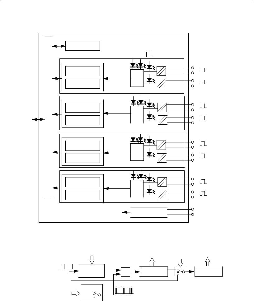
The 1794±IP4 module is an intelligent I/O module designed to perform high speed pulse counting. The module provides:
• 4 pulse transmitter interfaces, each with 2 optocoupled inputs
Each input has + and ± inputs for connection to transmitters with complementary and noncomplementary signals.
The pulse inputs can accept frequencies up to 100KHz. The module accepts and returns binary data.
The module's primary use is accurate, high-speed counting of pulses from flow meters or density meters. This includes quantity counting and speed calculations.
The module has 2 16±bit up/down counters per channel. Each of the 4 interfaces can be individually configured for:
•period time measurement using one 16±bit counter and accumulating pulse counting using the other 16±bit counter.
•period time measurement using a 32±bit counter.
An internal clock (1 or 10MHz) is used for period time measurement.
The number of periods of the input signal to be measured is selectable (1, 2, 4, 8, 16, 32, 64 and 128 periods).
The Pulse Counter has 4 identical pulse transmitter interfaces (12±24V dc), each with 2 signal inputs (N and D). Each input has + and ± connections to the pulse transmitter.
Publication 1794*UM016B-EN-P - August 2002
1±2 |
Overview of the Pulse Counter Module |
ontrol Word |
|
|
|
|
|
|
|
|
|
|
|
|
|
|
ptocouplers |
|
|
16 bit ounter |
+ |
|
+ |
|
|
ogic |
|
||||
|
|
|
|||
|
|
+ |
|
||
16 bit ounter |
|
|
|||
|
|
|
|||
|
|
|
|||
|
|
|
|
|
|
|
|
|
+ |
|
|
|
16 bit ounter |
|
|
|
|
|
|
|
ogic |
|
||
usSerial |
nterfaceus |
|
|
|
||
16 bit ounter |
|
+ |
|
|||
|
|
|
|
|||
|
|
|
|
|
|
|
|
|
|
|
|
|
|
|
|
16 bit ounter |
+ |
|
+ |
|
|
|
ogic |
|
|||
|
|
|
|
|
||
|
|
|
|
+ |
|
|
|
|
16 bit ounter |
|
|
||
|
|
|
|
|
|
|
|
|
|
|
|
|
16 bit ounter |
|
|
+ |
|
|
ogic |
|
||
|
|
|
||
|
|
+ |
|
|
16 bit ounter |
|
|
|
|
|
|
|
||
|
|
|
|
|
|
|
Gavanically solated |
12-24V dc |
|
|
Internal +5V dc |
0V |
|
|
|
dc/dc onverter |
|
||
|
|
|
||
|
|
|
|
Configuration is selected by setting A (below) in the appropriate position (variable SelectMeasureType). The arrows show signals (control words and registers) controlled by the control system.
Gate ontrol |
& |
16 bit ounter |
16 bit ounter |
|
1 128 periods |
||||
|
|
|
A
lock
1 z
10 z
ublication 17 41U 016 August 2002

Overview of the Pulse Counter Module |
1±3 |
What the Pulse Counter
Module Does
The Pulse Counter module performs high-speed scaling calculation operations for various industrial applications. The module interfaces with a FLEX I/O family adapter which then communicates with a programmable controller processor that has block-transfer capability and external I/O devices.
The adapter/power supply transfers data to the module (block transfer write) and from the module (block transfer read) using BTW and BTR instructions in your ladder diagram program. These instructions let the adapter read input values and status from the module, and let you write output values and configure the module's mode of operation. The following illustration describes the communication process.
1 |
2 |
The adapter transfers your configuration data to the module using a BTW.
External devices transmit frequency signals to the mod= ule.
Allen Bradley
ADAPTER |
LOCAL |
24VDC |
|||||||||
POWER SUPPLY |
|||||||||||
ACTIVE |
|
|
FAULT |
FAULT |
|||||||
|
|
RIO ADAPTER |
|||||||||
|
|
|
|
|
|
|
|
|
|
||
|
|
|
|
|
|
|
|
|
|
1794=ASB |
|
Flexbus
4
Your ladder program instructs the adapter to perform a BTR of the values and stores them in a data table.
5
Allen Bradley |
1794-IP4 |
|
4 CH Pulse Counter Module |
||
|
||
|
1 |
|
|
OK |
|
|
3 |
The adapter and module determine that the transfer was made without error and input values are within speci= fied range.
6
Your ladder program can use and/or move the data (if valid) before it is written over by the transfer of new data in a subsequent transfer.
7
Your ladder program performs BTWs to the module when you power it up, and any time you wish to reconfigure the module.
The module converts frequency signals into integer format and stores these values until the adapter requests their transfer.
Publication 1794=UM016B-EN-P - August 2002

1±4 |
Overview of the Pulse Counter Module |
Typical Applications
Input Capabilities
You can use the 1794±IP4 module in the power management, automotive, food and beverage, and oil and gas industries for various flow and/or turbine metering applications. Some sample applications include:
•quantity counting
•speed calulations
•brewery flow monitoring
•petrochemical flow and custody transfer
The Pulse Counter module has 4 identical input interfaces. Each of the input channels may accept + and ± input signals:
•N+ and N±
•D+ and D±
The pulse inputs can accept frequencies up to 100KHz. The module accepts and returns binary data.
Each of the 4 counters has two 16±bit counter registers.
Variables
Communication between the Pulse Counter module and the control system take place using variables accessible in the control system program. Examples of variables are:
•selection of clock frequency (ClockFrequency)
•selection of measurement type (SelectMeasureType).
Control words are used to set parameters for configuration. Control words sent to the Pulse Counter module are read back to the control system to verify that at least 1 I/O scan has been performed since the control system cycle which initiated the frequency module command.
Select Type of Measurement
The module can be configured for 2 alternate functions using the variable SelectMeasureType. Each of the 4 inputs can be individually configured.
SelectMeasureType Function
0Period time measurement using a 16-bit counter register and the function of a 16-bit accumulating counter
1Period time measurement using a 32-bit counter register
Publication 1794#UM016B-EN-P - August 2002

Overview of the Pulse Counter Module |
1±5 |
Start Period Time Measurement
The control bit StartMeasurement starts the measurement of the time period.
StartMeasurement Function
0Period time measurement stopped (not enabled)
1Period time measurement starts on the positive edge of the variable
Check if the Measurement is Complete
After a complete measurement the flag MeasurementReady is set.
MeasurementReady Function
0The measurement is not complete
1The positive edge of the flag indicates that the measurement is complete
MeasurementReady is reset by the module when a positive edge of
StartMeasurement is received.
Select Clock Frequency
The clock period for the period time measurement resolution selection can be set to 1 or 10MHz using the variable ClockFrequency. 10MHz clock frequency is recommended at 32±bit period time measurement to provide the best accuracy and resolution. Use 1mHz clock frequency at 16±bit frequencies to avoid overflow in the counter at frequencies over 15Hz.
ClockFrequency Function
0lock frequency = 10MHz
1lock frequency = 1MHz
Publication 1794.UM016 -EN-P - August 2002

1±6 |
Overview of the Pulse Counter Module |
Chapter Summary
Select Number of Periods
The number of periods to be measured can be selected using the variable NumberofPeriods.
NumberofPeriods Function
0Measure during 1 period
1Measure during 2 period
2Measure during 4 period
3Measure during 8 period
4Measure during 16 period
5Measure during 32 period
6Measure during 64 period
7Measure during 128 period
In this chapter, you learned about the Pulse Counter module, block transfer communication, and details of how the module functions. Now you can install the module.
2
Install the
IP4 Module
Publication 17 4%UM016 -EN-P - August 2002

t 2
How to Install Yo r P lse Co nter Mod le
What This Chapter
Contains
Before You Install Your
Input Module
In this chapter, we tell you about:
For information on |
|
See page |
|
|
|
Before You nstall Your odule |
|
|
European Union Directives |
|
|
Power Requirements |
|
|
nstalling the odule |
|
4 |
on a D rail |
4 |
|
on a wall panel |
|
6 |
on the terminal base |
7 |
|
Connecting Wiring |
9 |
|
odule ndicators |
5 |
|
|
|
|
Before installing your Pulse Counter module in the FLEX I/O system:
You need to: |
As described under: |
|
|
|
|
Calculate the power requirements of all |
Power Requirements page 5 |
|
modules in each F EX system |
||
|
||
|
|
|
Position the keyswitch on the terminal base |
nstalling the odule page 4 |
|
|
|
|
|
|
ATTENTION: The Pulse Counter module does not receive power from the backplane. +24V dc power
! must be applied to your module before installation. If power is not applied, the module position will appear to the adapter as an empty slot in your chassis.
European Union Directive
Compliance
If this product has the CE mark it is approved for installation within the European Union and EEA regions. It has been designed and tested to meet the following directives.
EMC Directive
This product is tested to meet Council Directive 89/336/EEC Electromagnetic Compatibility (EMC) and the following standards, in whole or in part, documented in a technical construction file:
•EN 50081-2EMC ± Generic Emission Standard, Part 2 ± Industrial Environment
•EN 50082-2EMC ± Generic Immunity Standard, Part 2 ± Industrial Environment
This product is intended for use in an industrial environment.
Publication 7945U 6B E P August

2±2 |
How to Install Your Pulse Counter Module |
Low Voltage Directive
This product is tested to meet Council Directive 73/23/EEC
Low Voltage, by applying the safety requirements of EN 61131±2
Programmable Controllers, Part 2 ± Equipment Requirements and
Tests.
For specific information required by EN 61131-2, see the appropriate sections in this publication, as well as the following Allen-Bradley publications:
•Industrial Automation Wiring and Grounding Guidelines For Noise Immunity, publication 1770-4.1
•Guidelines for Handling Lithium Batteries, publication AG-5.4
•Automation Systems Catalog, publication B111
Power Requirements
This equipment is classified as open equipment and must be mounted in an enclosure during operation to provide safety protection.
The wiring of the terminal base unit is determined by the current draw through the terminal base. Make certain that the current draw does not exceed 10A.
|
ATTENTION: Total current draw through the |
|
! |
terminal base unit is limited to 10A. Separate power |
|
connections may be necessary. |
||
|
||
|
|
Publication 1794 UM016B-EN-P - August 2002
How to Install Your Pulse Counter Module |
2±3 |
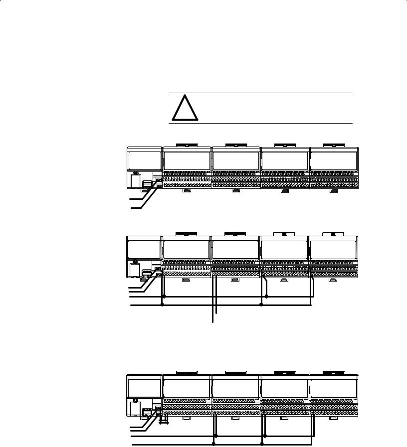
Methods of wiring the terminal base units are shown in the illustration below.
Wiring the Terminal Base Units (1794-TB3G shown)
ATTENTION: Do not daisy chain power or
!ground from the terminal base unit to any ac or dc digital module terminal base unit.
Daisy-chaining
|
|
|
|
Pulse Counter |
|
|
|
|
Pulse Counter |
|
|
TC/RTD/mV |
|
|
|
Pulse Counter |
||||||||
|
|
|
|
|
|
Module |
|
|
|
|
Module |
|
|
|
Module |
|
|
|
Module |
|||||
|
|
|
|
|
|
|
|
|
|
|
|
|
|
|
|
|
|
|
|
|
|
|
|
|
|
|
|
|
|
|
|
|
|
|
|
|
|
|
|
|
|
|
|
|
|
|
|
|
|
|
|
|
|
|
|
|
|
|
|
|
|
|
|
|
|
|
|
|
|
|
|
|
|
|
|
|
|
|
|
|
|
|
|
|
|
|
|
|
|
|
|
|
|
|
|
|
|
|
|
|
|
|
|
|
|
|
|
|
|
|
|
|
|
|
|
|
|
|
|
|
|
|
|
|
|
|
|
|
|
|
|
|
|
|
|
|
|
|
|
|
|
|
|
|
|
|
|
|
|
|
|
|
|
|
|
|
|
|
|
|
|
|
|
|
|
|
|
|
|
|
|
|
|
|
|
|
|
|
|
|
|
|
|
|
|
|
|
|
|
|
|
|
|
|
|
|
|
|
|
|
|
|
|
|
|
|
|
|
|
|
|
|
|
|
|
|
|
|
|
|
|
|
|
|
24V dc |
Note: All modules must be pulse, frequency or TC/RTD/mV modules for this configuration. |
|
|
Wiring when total current draw is less than 10A |
|
|
|
|
|
|
|
Individual
|
|
Digital Input |
|
|
Pulse Counter |
|
Digital Input |
|
Digital Output |
|||||
|
|
|
|
Module |
|
|
Module |
|
|
Module |
|
Module |
||
|
|
|
|
|
|
|
|
|
|
|
|
|
|
|
|
|
|
|
|
|
|
|
|
|
|
|
|
|
|
|
|
|
|
|
|
|
|
|
|
|
|
|
|
|
|
|
|
|
|
|
|
|
|
|
|
|
|
|
|
|
|
|
|
|
|
|
|
|
|
|
|
|
|
|
|
|
|
|
|
|
|
|
|
|
|
|
|
|
|
|
|
|
|
|
|
|
|
|
|
|
|
|
|
|
24V dc
24V dc
|
24V dc |
|
|
|
Note: Use this configuration if using any |
|
|
|
|
||
|
|
|
|
•noisy" dc digital I/O modules in your system. |
|
|
|
Pulse Counter Module wiring separate from digital wiring. |
|||
|
|
|
Wiring when total current draw is greater than 10A |
||
|
|
|
|
|
|
|
|
|
|
|
|
Combination |
|
|
|
|
|
Pulse Counter |
|
|
Pulse Counter |
TC/RTD/mV |
||
Module |
|
|
|
Module |
Module |
|
|
|
|
|
|
|
|
|
|
|
|
|
|
|
Pulse Counter |
Module |
24V dc
24V dc
Note: All modules powered by the same power supply
must be pulse, frequency or TC/RTD/mV modules for this configuration.
Total current draw through any base unit must not be greater than 10A
Publication 17942UM016B-EN-P - August 2002

2±4 |
How to Install Your Pulse Counter Module |
Installing the Module
Installation of the Pulse Counter module consists of:
•mounting the terminal base unit
•installing the module into the terminal base unit
•installing the connecting wiring to the terminal base unit
If you are installing your module into a terminal base unit that is already installed, proceed to ªMounting the Pulse Counter Module on the Terminal Baseº on page 2±7.
Mounting the Terminal Base Unit on a DIN Rail
ATTENTION: Do not remove or replace a terminal base unit when power is applied. Interruption of the
! flexbus can result in unintended operation or machine motion.
1. Remove the cover plug (if used) in the male connector of the unit to which you are connecting this terminal base unit.
2. Check to make sure that the 16 pins in the male connector on the adjacent device are straight and in line so that the mating female connector on this terminal base unit will mate correctly.
3. Position the terminal base on the 35 x 7.5mm DIN rail A (A-B pt. no. 199-DR1; 46277-3). Proceed as follows:
C  A
A
B
A
Position terminal base at a slight angle and hooked over the top of the DIN rail.
4.Make certain that the female flexbus connector C is fully retracted into the base unit.
Publication 1794(UM016B-EN-P - August 2002

How to Install Your Pulse Counter Module |
2±5 |
Slide the terminal base unit over tight against the adapter
Make sure the hook on the terminal base slides under the edge of the adapter and the flexbus connector is fully retracted
Press down on the terminal base unit to lock the terminal base on the DIN rail If the terminal base does not lock into place use a screwdriver or similar device to open the locking tab press down on the terminal
base until flush with the DIN rail and release the locking tab to lock the 30077±M base in place
Gently push the flexbus connector into the side
of the adapter to complete the backplane connection
2002
2±6 |
How to Install Your Pulse Counter Module |
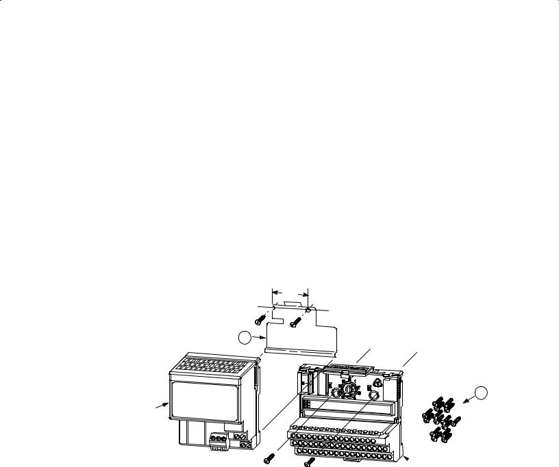
1794 NM1 Mounting Kit
Contents:
1 - Mounting late for Adapter
2 - 18 #6 self/tapping screws (2 for the adapter, and 2 each for up to 8 modules)
Adapter Module (not included)
5. Repeat the above steps to install the next terminal base.
Panel/Wall Mounting
Installation on a wall or panel consists of:
•laying out the drilling points on the wall or panel
•drilling the pilot holes for the mounting screws
•mounting the adapter mounting plate
•installing the terminal base units and securing them to the wall or panel
If you are installing your module into a terminal base unit that is already installed, proceed to ªMounting the Pulse Counter Module on the Terminal Baseº on page2±7.
Use the mounting kit Cat. No. 1794-NM1 for panel/wall mounting.
1.4
(35.5)
1
2
 Terminal Base Unit
(not included)
To install the mounting plate on a wall or panel:
1.Lay out the required points on the wall/panel as shown in the drilling dimension drawing.
ublication 1794/UM016B-EN- - August 2002
 Loading...