


 Loading...
Altivar 71
Integrated Modbus
User's manual
11/2010 |
1755863
www.schneider-electric.com

Contents
Before you begin_____________________________________________________________________________________________ 4
Documentation structure_______________________________________________________________________________________ 5
Introduction_________________________________________________________________________________________________ 6 Presentation _____________________________________________________________________________________________ 6 Notation ________________________________________________________________________________________________ 6
Bus connection ______________________________________________________________________________________________ 7 Connecting to the Altivar 71 _________________________________________________________________________________ 7 RJ45 connector pinouts ____________________________________________________________________________________ 7 Wiring recommendations ___________________________________________________________________________________ 8 RS485 standard __________________________________________________________________________________________ 8 Modbus standard schematic_________________________________________________________________________________ 9 Connection via RJ45 wiring system __________________________________________________________________________ 10 Connection via junction boxes ______________________________________________________________________________ 12 Connection onto screw terminals ____________________________________________________________________________ 14
Configuration ______________________________________________________________________________________________ 15 Configuring communication parameters_______________________________________________________________________ 15 Control-signal configuration ________________________________________________________________________________ 16 Configuring the communication scanner ______________________________________________________________________ 19 Configuring monitored parameters ___________________________________________________________________________ 20 Configuring communication fault management _________________________________________________________________ 21
Diagnostics ________________________________________________________________________________________________ 22 LEDs__________________________________________________________________________________________________ 22 Communication diagnostics ________________________________________________________________________________ 23 Control-signal diagnostics__________________________________________________________________________________ 25 Communication faults _____________________________________________________________________________________ 27
Modbus protocol ____________________________________________________________________________________________ 28 RTU mode _____________________________________________________________________________________________ 28 Principle _______________________________________________________________________________________________ 28 Altivar 71 Integrated Modbus _______________________________________________________________________________ 29 Addresses______________________________________________________________________________________________ 29 Modbus functions ________________________________________________________________________________________ 30 Read N output words: Function 3 ____________________________________________________________________________ 30 Write one output word: Function 6 ___________________________________________________________________________ 31 Diagnostics: Function 8 ___________________________________________________________________________________ 32 Write N output words: Function 16 (16#10) ____________________________________________________________________ 33 Identification: Function 43 (16#2B)___________________________________________________________________________ 34 Read/write N words: Function 23 (16#17) _____________________________________________________________________ 36 Communication scanner ___________________________________________________________________________________ 37 Exception responses _____________________________________________________________________________________ 39 Read non-existent or protected parameters ____________________________________________________________________ 39
Appendix: Non-standard schematics ____________________________________________________________________________ 41 UNI-TELWAY schematic __________________________________________________________________________________ 41 Jbus schematic__________________________________________________________________________________________ 42 Use of UNI-TELWAY slaves in a standard schematic ____________________________________________________________ 43 Recommendations for setting up a Modbus network using non-standard devices_______________________________________ 44
While every precaution has been taken in the preparation of this document, Schneider Electric SA assumes no liability for any omissions or errors it may contain, nor for any damages resulting from the application or use of the information herein.
The products and options described in this document may be changed or modified at any time, either from a technical point of view or in the way they are operated. Their description can in no way be considered contractual.
1755863 |
11/2010 |
3 |

Before you begin
Read and understand these instructions before performing any procedure with this drive.
 DANGER
HAZARDOUS VOLTAGE
•Read and understand this manual before installing or operating the Altivar 71 drive. Installation, adjustment, repair, and maintenance must be performed by qualified personnel.
•The user is responsible for compliance with all international and national electrical standards in force concerning protective grounding of all equipment.
•Many parts in this variable speed drive, including printed wiring boards, operate at line voltage. DO NOT TOUCH. Use only electrically insulated tools.
•DO NOT touch unshielded components or terminal strip screw connections with voltage present.
•DO NOT short across terminals PA and PC or across the DC bus capacitors.
•Install and close all covers before applying power or starting and stopping the drive.
•Before servicing the variable speed drive:
-Disconnect all power
-Place a "DO NOT TURN ON" label on the variable speed drive disconnect
-Lock the disconnect in the open position
•Disconnect all power including external control power that may be present before servicing the drive. WAIT 15 MINUTES for the DC bus capacitors to discharge. Then follow the DC bus voltage measurement procedure given in the Installation Manual to verify that the DC voltage is less than 45 Vdc. The drive LEDs are not accurate indicators of the absence of DC bus voltage.
Electric shock will result in death or serious injury
CAUTION
DAMAGED EQUIPMENT
Do not operate or install any drive that appears damaged.
Failure to follow this instruction can result in equipment damage.
4 |
1755863 |
11/2010 |

Documentation structure
Installation manual
This manual describes:
•How to assemble the drive
•How to connect the drive
Programming manual
This manual describes:
•The functions
•The parameters
•How to use the drive display terminal (integrated display terminal and graphic display terminal)
Communication parameters manual
This manual describes:
•The drive parameters with specific information (addresses, formats, etc.) for use via a bus or communication network
•The operating modes specific to communication (status chart)
•The interaction between communication and local control
Modbus®, CANopen®, Ethernet™, Profibus®, INTERBUS, Uni-Telway, FIPIO, DeviceNet™, Modbus® Plus manuals ...
These manuals describe:
•Connection to the bus or network
•Configuration of the communication-specific parameters via the integrated display terminal or the graphic display terminal
•Diagnostics
•Software setup
•The communication services specific to the protocol
Altivar 58/58F migration manual
This manual describes the differences between the Altivar 71 and the Altivar 58/58F.
It explains how to replace an Altivar 58 or 58F, including how to replace drives communicating on a bus or network.
1755863 |
11/2010 |
5 |

Introduction
Presentation
Two integrated communication ports mean that the Modbus protocol can be accessed directly:
•One RJ45 Modbus HMI connector port, located on the drive front panel, which is used to connect:
-The graphic display terminal
-A Magelis industrial HMI terminal
-The PC-Software workshop
•One RJ45 Modbus network port, located on the drive control terminals, which is dedicated to control and signaling by a PLC or other type of controller. It also supports the connection of a terminal or the PC software workshop when the terminal port is not available.
The two Modbus ports on the Altivar 71 can be used for the following functions:
•Configuration
•Adjustment
•Control
•Monitoring
The Altivar 71 supports:
•The 2-wire RS485 physical layer
•The RTU transmission mode
This manual describes how to set up the Altivar 71 drive on Modbus and also describes the Modbus services that are available on this drive.
Notation
Drive terminal displays
The graphic display terminal menus are shown in square brackets.
Example: [1.9 COMMUNICATION].
The integrated 7-segment display terminal menus are shown in round brackets.
Example: (COM-).
Parameter names are displayed on the graphic display terminal in square brackets.
Example: [Fallback speed]
Parameter codes are displayed on the integrated 7-segment display terminal in round brackets.
Example: (LFF).
Formats
In this manual, hexadecimal values are written as follows: 16#.
6 |
1755863 |
11/2010 |

Bus connection
Connecting to the Altivar 71
Connection accessories should be ordered separately (please consult our catalogs).
Connect the RJ45 cable connector to either of the RJ45 connectors on the Altivar 71:
Modbus
HMI
Modbus network
RJ45 connector pinouts |
|
|
|
||
View from underneath |
Modbus network |
Modbus HMI |
|||
|
Pin |
Signal |
Pin |
Signal |
|
|
1 |
CAN_H (1) |
1 |
Not connected |
|
|
2 |
CAN_L (1) |
2 |
Not connected |
|
|
3 |
CAN_GND (1) |
3 |
Not connected |
|
|
4 |
D1 |
4 |
D1 |
|
|
5 |
D0 |
5 |
D0 |
|
8........................1 |
6 |
Not connected |
6 |
Not connected |
|
7 |
VP (2) |
7 |
VP (2) |
||
|
|||||
|
8 |
Common |
8 |
Common |
|
(1)CANopen® signal.
(2)Power supply (c 10 V 20 mA) for an RS232/RS485 converter (to PC-Software) or for the graphic display terminal.
Note: Avoid using pins marked “Not connected”.
1755863 |
11/2010 |
7 |

Bus connection
Wiring recommendations
•Use the Schneider-Electric cable with 2 pairs of shielded twisted conductors (catalog number: TSXCSA100, TSXCSA200 or TSXCSA500).
•Keep the Modbus cable away from the power cables (30 cm minimum).
•If it is necessary for the Modbus cable and the power cables to cross each other, be sure they cross at right angles.
•Whenever possible, connect the cable shielding to the protective ground, e.g., to the ground of each device if this ground is connected to the protective ground.
•Install a line terminator at both ends of the line.
•Ensure the correct polarization of the line.
•Connect the common polarity (“Common” signal) to the protective ground at one or more points on the bus.
For more information, please refer to the TSX DG KBL E guide: "Electromagnetic compatibility of industrial networks and fieldbuses".
RS485 standard
The RS485 standard allows variants of different characteristics:
•Polarization
•Line terminator
•Distribution of a reference potential
•Number of slaves
•Length of bus
The new Modbus specification published on www.modbus.org in 2002 contains precise details of all these characteristics. They are also summarized in the next paragraph (standard schematic). The new Schneider-Electric devices conform to this specification.
Some devices comply with earlier specifications. The two most widespread are described in the appendices:
•"Uni-Telway schematic" page 41
•"Jbus schematic" page 42
Requirements enabling different types of protocol to coexist are given in the appendix:
• "Mixed schematic" page 43
8 |
1755863 |
11/2010 |
Bus connection
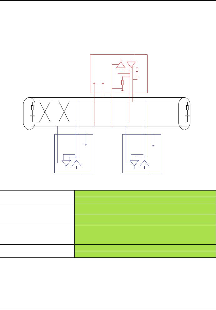
Modbus standard schematic
The standard schematic corresponds to the Modbus specification published in 2002 on www.modbus.org (Modbus_over_serial_line_V1.pdf, Nov 2002) and in particular to the schematic of the 2-wire multidrop serial bus.
The ATV71 drive conforms to this specification.
Schematic diagram:
Master
R |
T |
5 V |
|
650 Ω
650 Ω
0 V
|
D1 |
120 Ω |
120 Ω |
1n F |
1n F |
|
D0 |
|
Common |
R |
T |
R |
T |
|
|
Slave 1 Slave n
Type of trunk cable
Maximum length of bus
Maximum number of stations (without repeater)
Maximum length of tap links
Bus polarization
Line terminator
Common polarity
Shielded cable with 1 twisted pair and at least a 3rd conductor
1000 m at 19200 bps with the Schneider-Electric TSX CSAp cable
32 stations, i.e., 31 slaves
•20 m for one tap link
•40 m divided by the number of tap links on a multiple junction box
•One 450 to 650 Ω pulldown resistor at 5 V (650 Ω or thereabouts recommended)
•One 450 to 650 Ω pulldown resistor at Common
(650 Ω or thereabouts recommended) This polarization is recommended for the master.
One 120 Ω 0.25 W resistor in series with a 1nF 10 V capacitor
Yes (Common), connected to the protective ground at one or more points on the bus
1755863 |
11/2010 |
9 |
Bus connection |
|
|
|
|
|||
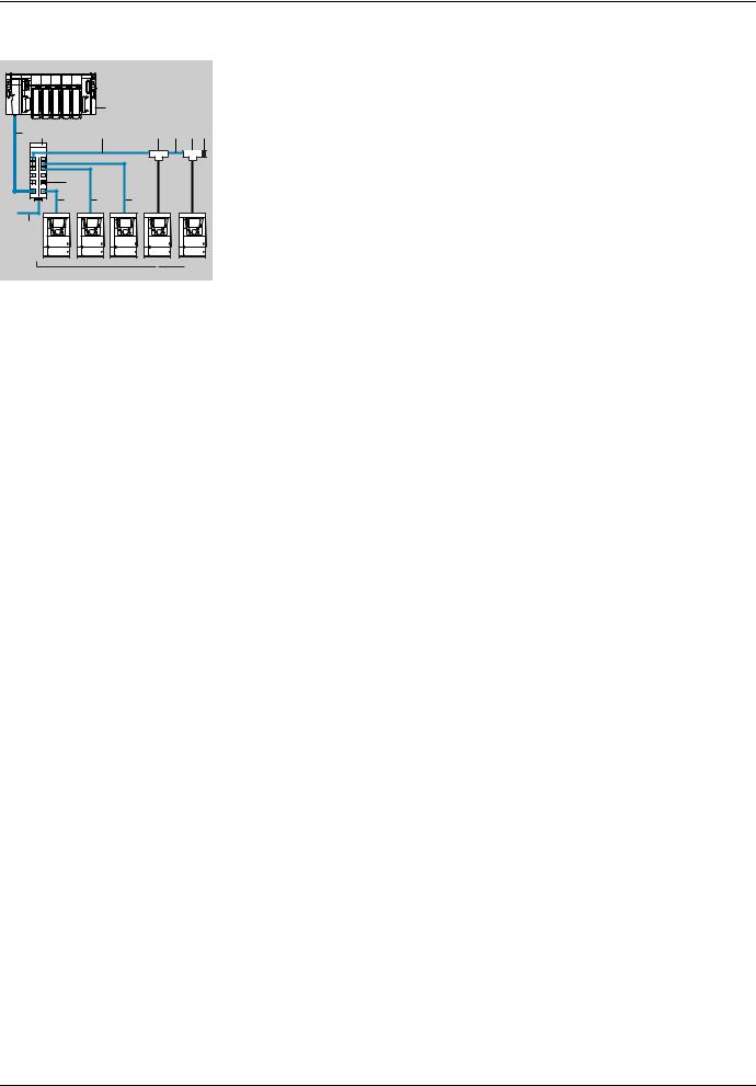
Connection via RJ45 wiring system |
|||||||
|
|
|
|
|
|
1. |
Master (PLC, PC or communication module) |
|
|
|
1 |
|
|
2. |
Modbus cable depending on the type of master (see table) |
|
|
|
|
|
|
|
|
2 |
3 |
4 |
6 |
4 |
6 5 |
3. |
Modbus splitter block LU9 GC3 |
|
|
||||||
|
|
|
|
|
|
4. |
Modbus drop cables VW3 A8 306 Rpp |
|
5 |
|
|
|
|
5. |
Line terminators VW3 A8 306 RC |
|
4 |
4 |
4 |
|
|
||
|
|
|
|
|
|||
7 |
|
|
|
|
|
6. |
Modbus T-junction boxes VW3 A8 306 TFpp (with cable) |
|
|
|
|
|
|
|
|
|
|
|
|
|
|
7. |
Modbus cable (to another splitter block) TSX CSAp00 |
|
ATV 71 |
|
|
|
|
|
|
Connection accessories
Description |
|
|
Code |
Catalog number |
||
Modbus splitter |
|
10 RJ45 connectors and 1 screw terminal block |
3 |
LU9 GC3 |
|
|
block |
|
|
|
|
|
|
|
|
|
|
|
|
|
Modbus T-junction boxes |
With integrated cable (0.3 m) |
6 |
VW3 A8 |
306 |
TF03 |
|
|
|
|
|
|
|
|
|
|
With integrated cable (1 m) |
6 |
VW3 A8 |
306 |
TF10 |
|
|
|
|
|
|
|
Line |
For RJ45 connector |
R = 120 Ω, C = 1 nF |
5 |
VW3 A8 |
306 RC |
|
terminators |
|
|
|
|
|
|
|
R = 150 Ω (specific to "Jbus schematic" page 42) |
5 |
VW3 A8 |
306 |
R |
|
|
|
|||||
|
|
|
|
|
|
|
Connecting cables
Description |
Length (m) |
Connectors |
Code |
Catalog number |
|
Cables for |
3 |
1 RJ45 connector and 1 stripped end |
|
VW3 A8 306 D30 |
|
Modbus bus |
|
|
|
|
|
0.3 |
2 RJ45 connectors |
4 |
VW3 A8 306 R03 |
||
|
|||||
|
|
|
|
|
|
|
1 |
2 RJ45 connectors |
4 |
VW3 A8 306 R10 |
|
|
|
|
|
|
|
|
3 |
2 RJ45 connectors |
4 |
VW3 A8 306 R30 |
|
|
|
|
|
|
|
RS 485 double |
100 |
Supplied without connector |
7 |
TSX CSA 100 |
|
shielded twisted |
|
|
|
|
|
200 |
Supplied without connector |
7 |
TSX CSA 200 |
||
pair cables |
|||||
|
|
|
|
||
|
500 |
Supplied without connector |
7 |
TSX CSA 500 |
|
|
|
|
|
|
10 |
1755863 |
11/2010 |
Bus connection
Type of master |
Master interface |
Modbus connection accessories for RJ45 wiring system |
|
|
|
|
|
|
|
Description |
Catalog number |
Twido PLC |
Adaptor or mini-DIN |
3 m cable equipped with a mini-DIN connector and an RJ45 |
TWD XCA RJ030 |
|
RS485 interface module |
connector |
|
|
|
|
|
|
Adaptor or screw |
3 m cable equipped with an RJ45 connector and stripped at |
VW3 A8 306 D30 |
|
terminal RS485 |
the other end |
|
|
interface module |
|
|
|
|
|
|
TSX Micro PLC |
Mini-DIN RS485 |
3 m cable equipped with a mini-DIN connector and an RJ45 |
TWD XCA RJ030 |
|
connector port |
connector |
|
|
|
|
|
|
PCMCIA card (TSX |
Stripped cable |
TSX SCP CM 4030 |
|
SCP114) |
|
|
|
|
|
|
TSX Premium PLC |
TSX SCY 11601 or TSX |
Cable equipped with a SUB-D 25 connector and stripped at |
TSX SCY CM 6030 |
|
SCY 21601 module |
the other end (for connection to the screw terminals of the |
|
|
(SUB-D 25 socket) |
LU9GC3 splitter block) |
|
|
|
|
|
|
PCMCIA card |
Stripped cable |
TSX SCP CM 4030 |
|
(TSX SCP114) |
|
|
|
|
|
|
Ethernet bridge |
Screw terminal RS485 |
3 m cable equipped with an RJ45 connector and stripped at |
VW3 A8 306 D30 |
(174 CEV 300 10) |
|
the other end |
|
|
|
|
|
Profibus DP gateway |
RJ45 RS485 |
1 m cable equipped with 2 RJ45 connectors |
VW3 P07 306 R10 |
(LA9P307) |
|
|
|
|
|
|
|
Fipio (LUFP1) or |
RJ45 RS485 |
0.3 m cable equipped with 2 RJ45 connectors or |
VW3 A8 306 R03 or |
Profibus DP (LUFP7) or |
|
1 m cable equipped with 2 RJ45 connectors or |
VW3 A8 306 R10 or |
DeviceNet (LUFP9) |
|
3 m cable equipped with 2 RJ45 connectors |
VW3 A8 306 R30 |
gateway |
|
|
|
|
|
|
|
Serial port PC |
Male SUB-D 9 |
RS232/RS485 converter and 3 m cable equipped with an |
TSX SCA 72 and |
|
RS232 serial port PC |
RJ45 connector and stripped at the other end (for |
VW3 A8 306 D30 |
|
|
connection to the screw terminals of the LU9GC3 splitter |
|
|
|
block) |
|
|
|
|
|
1755863 |
11/2010 |
11 |
Bus connection
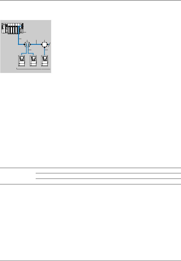
Connection via junction boxes
1. Master (PLC, PC or communication module)
1 |
2.Modbus cable depending on the type of master
3.Modbus cable TSX CSAp00
2 |
5 |
3 |
4 |
|
|
|
|
4. |
Junction box TSX SCA 50 |
|
|
6 |
7 5. |
Subscriber sockets TSX SCA 62 |
|
|
|
6. |
Modbus drop cables VW3 A8 306 |
|
|
|
7. |
Modbus drop cable VW3 A8 306 D30 |
ATV 71
Connection accessories
Description |
Code |
Catalog number |
Tap junction |
4 |
TSX SCA 50 |
3 screw terminals and an RC line terminator, to be connected using cable VW3 A8 306 D30 |
|
|
|
|
|
Subscriber socket |
5 |
TSX SCA 62 |
2 female 15-way SUB-D connectors, 2 screw terminals, and an RC line terminator, to be connected |
|
|
using cable VW3 A8 306 or VW3 A8 306 D30 |
|
|
|
|
|
Connecting cables
Description |
Length (m) |
Connectors |
Code |
Catalog number |
|
Cables for Modbus bus |
3 |
1 RJ45 connector and one stripped end |
7 |
VW3 A8 |
306 D30 |
|
|
|
|
|
|
|
3 |
1 RJ45 connector and 1 male 15-way SUB-D connector for |
6 |
VW3 A8 |
306 |
|
|
TSX SCA 62 |
|
|
|
RS 485 double shielded 100 |
|
twisted pair cables |
200 |
|
|
|
500 |
Supplied without connector |
3 |
TSX CSA 100 |
Supplied without connector |
3 |
TSX CSA 200 |
Supplied without connector |
3 |
TSX CSA 500 |
12 |
1755863 |
11/2010 |

Bus connection
Type of master |
Master interface |
Modbus connection accessories for junction boxes using screw |
|
|
|
terminals |
|
|
|
Description |
Catalog number |
Twido PLC |
Adaptor or screw terminal |
Modbus cable |
TSX CSA100 or |
|
RS485 interface module |
|
TSX CSA200 or |
|
|
|
TSX CSA500 |
|
|
|
|
TSX Micro PLC |
Mini-DIN RS485 |
Tap junction |
TSX P ACC 01 |
|
connector port |
|
|
|
|
|
|
|
PCMCIA card |
Cable equipped with a special connector and |
TSX SCP CU 4030 |
|
(TSX SCP114) |
stripped at the other end |
|
|
|
|
|
TSX Premium PLC |
TSX SCY 11601 or TSX SCY |
Cable equipped with a SUB-D 25 connector |
TSX SCY CM 6030 |
|
21601 module |
and stripped at the other end |
|
|
(SUB-D 25 socket) |
|
|
|
|
|
|
|
PCMCIA card |
Cable equipped with a special connector and |
TSX SCP CU 4030 |
|
(TSX SCP114) |
stripped at the other end |
|
|
|
|
|
Ethernet bridge |
Screw terminal RS485 |
Modbus cable |
TSX CSA100 or |
(174 CEV 300 10) |
|
|
TSX CSA200 or |
|
|
|
TSX CSA500 |
|
|
|
|
Profibus DP gateway |
RJ45 RS485 |
3 m cable equipped with an RJ45 connector |
VW3 A8 306 D30 |
(LA9P307) |
|
and stripped at the other end |
|
|
|
|
|
Fipio (LUFP1) or |
RJ45 RS485 |
3 m cable equipped with an RJ45 connector |
VW3 A8 306 D30 |
Profibus DP (LUFP7) or |
|
and stripped at the other end |
|
DeviceNet (LUFP9) gateway |
|
|
|
|
|
|
|
Serial port PC |
Male SUB-D 9 |
RS232/RS485 converter and |
TSX SCA 72 and |
|
RS232 serial port PC |
Modbus cable |
TSX CSA100 or |
|
|
|
TSX CSA200 or |
|
|
|
TSX CSA500 |
|
|
|
|
Type of master |
Master interface |
Modbus connection accessories for junction boxes using |
|
|
|
SUB-D 15 |
|
|
|
Description |
Catalog number |
Twido PLC |
Adaptor or screw terminal RS485 |
- |
- |
|
interface module |
|
|
|
|
|
|
TSX Micro PLC |
Mini-DIN RS485 connector port |
- |
- |
|
|
|
|
|
PCMCIA card (TSX SCP114) |
Cable equipped with a special connector and a |
TSX SCY CU |
|
|
SUB-D 25 connector |
4530 |
|
|
|
|
TSX Premium PLC |
TSX SCY 11601 or TSX SCY |
Cable equipped with a SUB-D 25 connector and |
TSX SCP CU |
|
21601 module (SUB-D 25 |
stripped at the other end |
4530 |
|
socket) |
|
|
|
|
|
|
|
PCMCIA card (TSX SCP114) |
Cable equipped with a special connector and |
TSX SCY CU |
|
|
stripped at the other end |
4530 |
|
|
|
|
Ethernet bridge |
Screw terminal RS485 |
- |
- |
(174 CEV 300 10) |
|
|
|
|
|
|
|
Profibus DP gateway |
RJ45 RS485 |
- |
- |
(LA9P307) |
|
|
|
|
|
|
|
Fipio gateway (LUFP1) or |
RJ45 RS485 |
3 m cable equipped with an RJ45 connector and |
VW3 A8 306 |
Profibus DP gateway (LUFP7) |
|
a SUB-D 25 connector |
|
|
|
|
|
Serial port PC |
Male SUB-D 9 RS232 serial port |
- |
- |
|
PC |
|
|
|
|
|
|
1755863 |
11/2010 |
13 |

Bus connection
Connection onto screw terminals
Connection accessories
Description |
|
|
|
Catalog number |
|
Line |
For screw terminals |
R = 120 |
Ω, C = 1 nF |
VW3 A8 |
306 DRC |
terminators |
|
|
|
|
|
|
R = 150 |
Ω |
VW3 A8 |
306 DR |
|
|
|
||||
|
|
(specific to "Jbus schematic" page 42) |
|
|
|
|
|
|
|
|
|
Connecting cables
Description |
Length (m) |
Connectors |
Catalog number |
|
Cables for |
3 |
1 RJ45 connector |
VW3 A8 306 D30 |
|
Modbus bus |
|
and one stripped end |
|
|
|
|
|
|
|
RS 485 double shielded |
100 |
Supplied without connector |
TSX CSA 100 |
|
twisted pair cables |
|
|
|
|
200 |
Supplied without connector |
TSX CSA 200 |
||
|
||||
|
|
|
|
|
|
500 |
Supplied without connector |
TSX CSA 500 |
|
|
|
|
|
14 |
1755863 |
11/2010 |
Loading...