


Schneider Electric PM870, PM850, PM810, PM820 User Manual

PowerLogic™ Series 800 Power Meter
PM810, PM820, PM850, & PM870
User Guide
63230-500-225A2
03/2011


63230-500-225A2 PowerLogicTM Series 800 Power Meter
DANGER
WARNING
CAUTION
CAUTION
3/2011
HAZARD CATEGORIES AND SPECIAL SYMBOLS
Read these instructions carefully and look at the equipment to become familiar with the
device before trying to install, operate, service, or maintain it. The following special
messages may appear throughout this bulletin or on the equipment to warn of potential
hazards or to call attention to information that clarifies or simplifies a procedure.
The addition of either symbol to a “Danger” or “Warning” safety label indicates that an
electrical hazard exists which will result in personal injury if the instructions are not
followed.
This is the safety alert symbol. It is used to alert you to potential personal injury hazards.
Obey all safety messages that follow this symbol to avoid possible injury or death.
DANGER indicates an imminently hazardous situation which, if not
avoided, will result in death or serious injury.
WARNING indicates a potentially hazardous situation which, if not
avoided, can result in death or serious injury.
CAUTION indicates a potentially hazardous situation which, if not
avoided, can result in minor or moderate injury.
CAUTION, used without the safety alert symbol, indicates a potentially
hazardous situation which, if not avoided, can result in property
damage.
NOTE: Provides additional information to clarify or simplify a procedure.
PLEASE NOTE
Electrical equipment should be installed, operated, serviced, and maintained only by
qualified personnel. No responsibility is assumed by Schneider Electric for any
consequences arising out of the use of this material.
CLASS A FCC STATEMENT
This equipment has been tested and found to comply with the limits for a Class A digital
device, pursuant to part 15 of the FCC Rules. These limits are designed to provide
reasonable protection against harmful interference when the equipment is operated in a
commercial environment. This equipment generates, uses, and can radiate radio frequency
energy and, if not installed and used in accordance with the instruction manual, may cause
harmful interference to radio communications. Operation of this equipment in a residential
area is likely to cause harmful interference in which case the user will be required to correct
the interference at his own expense. This Class A digital apparatus complies with Canadian
ICES-003.
© 2011 Schneider Electric. All Rights Reserved.
iii

PowerLogicTM Series 800 Power Meter 63230-500-225A2
3/2011
iv
© 2011 Schneider Electric. All Rights Reserved.

63230-500-225A2 PowerLogicTM Series 800 Power Meter
3/2011 Contents
Contents
Chapter 1—Introduction - - - - - - - - - - - - - - - - - - - - - - - - - - - - - - - - - - - - - - - - - - - - - 1
Topics Not Covered In This Manual - - - - - - - - - - - - - - - - - - - - - - - - - - - - - - - - - - - 1
What is a Power Meter? - - - - - - - - - - - - - - - - - - - - - - - - - - - - - - - - - - - - - - - - - - - 1
Power Meter Hardware - - - - - - - - - - - - - - - - - - - - - - - - - - - - - - - - - - - - - - - - - - - - 2
Box Contents - - - - - - - - - - - - - - - - - - - - - - - - - - - - - - - - - - - - - - - - - - - - - - - - - - - 6
Features - - - - - - - - - - - - - - - - - - - - - - - - - - - - - - - - - - - - - - - - - - - - - - - - - - - - - - 7
Firmware - - - - - - - - - - - - - - - - - - - - - - - - - - - - - - - - - - - - - - - - - - - - - - - - - - - - - - 7
Chapter 2—Safety Precautions - - - - - - - - - - - - - - - - - - - - - - - - - - - - - - - - - - - - - - - - 9
Chapter 3—Operation - - - - - - - - - - - - - - - - - - - - - - - - - - - - - - - - - - - - - - - - - - - - - - 11
Power Meter Display - - - - - - - - - - - - - - - - - - - - - - - - - - - - - - - - - - - - - - - - - - - - - 11
How the Buttons Work - - - - - - - - - - - - - - - - - - - - - - - - - - - - - - - - - - - - - - - - - - - - 11
Changing Values - - - - - - - - - - - - - - - - - - - - - - - - - - - - - - - - - - - - - - - - - - - - - - - 11
Menu Overview - - - - - - - - - - - - - - - - - - - - - - - - - - - - - - - - - - - - - - - - - - - - - - - - 11
Power Meter Setup - - - - - - - - - - - - - - - - - - - - - - - - - - - - - - - - - - - - - - - - - - - - - - 13
Power Meter Resets - - - - - - - - - - - - - - - - - - - - - - - - - - - - - - - - - - - - - - - - - - - - - 23
Power Meter Diagnostics - - - - - - - - - - - - - - - - - - - - - - - - - - - - - - - - - - - - - - - - - - 25
Chapter 4—Metering Capabilities - - - - - - - - - - - - - - - - - - - - - - - - - - - - - - - - - - - - - 27
Real-Time Readings - - - - - - - - - - - - - - - - - - - - - - - - - - - - - - - - - - - - - - - - - - - - - 27
Power Factor Min/Max Conventions - - - - - - - - - - - - - - - - - - - - - - - - - - - - - - - - - - 28
Power Factor Sign Conventions - - - - - - - - - - - - - - - - - - - - - - - - - - - - - - - - - - - - - 29
Demand Readings - - - - - - - - - - - - - - - - - - - - - - - - - - - - - - - - - - - - - - - - - - - - - - 30
Energy Readings - - - - - - - - - - - - - - - - - - - - - - - - - - - - - - - - - - - - - - - - - - - - - - - 35
Energy-Per-Shift (PM810 with PM810LOG) - - - - - - - - - - - - - - - - - - - - - - - - - - - - - 36
Power Analysis Values - - - - - - - - - - - - - - - - - - - - - - - - - - - - - - - - - - - - - - - - - - - 37
Chapter 5—Input/Output Capabilities - - - - - - - - - - - - - - - - - - - - - - - - - - - - - - - - - - 39
Digital Inputs - - - - - - - - - - - - - - - - - - - - - - - - - - - - - - - - - - - - - - - - - - - - - - - - - - 39
Demand Synch Pulse Input - - - - - - - - - - - - - - - - - - - - - - - - - - - - - - - - - - - - - - - - 40
Relay Output Operating Modes - - - - - - - - - - - - - - - - - - - - - - - - - - - - - - - - - - - - - 40
Solid-state KY Pulse Output - - - - - - - - - - - - - - - - - - - - - - - - - - - - - - - - - - - - - - - - 42
Fixed Pulse Output - - - - - - - - - - - - - - - - - - - - - - - - - - - - - - - - - - - - - - - - - - - - - 43
Calculating the Kilowatthour-Per-Pulse Value - - - - - - - - - - - - - - - - - - - - - - - - - - - 43
Analog Inputs - - - - - - - - - - - - - - - - - - - - - - - - - - - - - - - - - - - - - - - - - - - - - - - - - - 44
Analog Outputs - - - - - - - - - - - - - - - - - - - - - - - - - - - - - - - - - - - - - - - - - - - - - - - - - 44
Chapter 6—Alarms - - - - - - - - - - - - - - - - - - - - - - - - - - - - - - - - - - - - - - - - - - - - - - - - 45
Basic Alarms - - - - - - - - - - - - - - - - - - - - - - - - - - - - - - - - - - - - - - - - - - - - - - - - - - - - 45
Basic Alarm Groups - - - - - - - - - - - - - - - - - - - - - - - - - - - - - - - - - - - - - - - - - - - - - 45
Setpoint-driven Alarms - - - - - - - - - - - - - - - - - - - - - - - - - - - - - - - - - - - - - - - - - - - 46
Priorities - - - - - - - - - - - - - - - - - - - - - - - - - - - - - - - - - - - - - - - - - - - - - - - - - - - - - 47
Viewing Alarm Activity and History - - - - - - - - - - - - - - - - - - - - - - - - - - - - - - - - - - - 47
Types of Setpoint-controlled Functions - - - - - - - - - - - - - - - - - - - - - - - - - - - - - - - - 47
Scale Factors - - - - - - - - - - - - - - - - - - - - - - - - - - - - - - - - - - - - - - - - - - - - - - - - - - 49
Scaling Alarm Setpoints - - - - - - - - - - - - - - - - - - - - - - - - - - - - - - - - - - - - - - - - - - 50
Alarm Conditions and Alarm Numbers - - - - - - - - - - - - - - - - - - - - - - - - - - - - - - - - 50
Advanced Alarms- - - - - - - - - - - - - - - - - - - - - - - - - - - - - - - - - - - - - - - - - - - - - - - - - 53
Advanced Alarm Groups - - - - - - - - - - - - - - - - - - - - - - - - - - - - - - - - - - - - - - - - - - 53
Alarm Levels - - - - - - - - - - - - - - - - - - - - - - - - - - - - - - - - - - - - - - - - - - - - - - - - - - 54
Viewing Alarm Activity and History - - - - - - - - - - - - - - - - - - - - - - - - - - - - - - - - - - - 54
Alarm Conditions and Alarm Numbers - - - - - - - - - - - - - - - - - - - - - - - - - - - - - - - - 55
Chapter 7—Logging - - - - - - - - - - - - - - - - - - - - - - - - - - - - - - - - - - - - - - - - - - - - - - - 57
Introduction - - - - - - - - - - - - - - - - - - - - - - - - - - - - - - - - - - - - - - - - - - - - - - - - - - - 57
Memory Allocation for Log Files - - - - - - - - - - - - - - - - - - - - - - - - - - - - - - - - - - - - - 58
Alarm Log - - - - - - - - - - - - - - - - - - - - - - - - - - - - - - - - - - - - - - - - - - - - - - - - - - - - 58
Maintenance Log - - - - - - - - - - - - - - - - - - - - - - - - - - - - - - - - - - - - - - - - - - - - - - - 58
Data Logs - - - - - - - - - - - - - - - - - - - - - - - - - - - - - - - - - - - - - - - - - - - - - - - - - - - - 60
Billing Log - - - - - - - - - - - - - - - - - - - - - - - - - - - - - - - - - - - - - - - - - - - - - - - - - - - - 61
© 2011 Schneider Electric. All Rights Reserved.
v

TM
PowerLogic
Contents 3/2011
Series 800 Power Meter 63230-500-225A2
Chapter 8—Waveform Capture - - - - - - - - - - - - - - - - - - - - - - - - - - - - - - - - - - - - - - -63
Introduction - - - - - - - - - - - - - - - - - - - - - - - - - - - - - - - - - - - - - - - - - - - - - - - - - - - -63
Waveform Capture - - - - - - - - - - - - - - - - - - - - - - - - - - - - - - - - - - - - - - - - - - - - - - -63
Waveform Storage - - - - - - - - - - - - - - - - - - - - - - - - - - - - - - - - - - - - - - - - - - - - - - -64
How the Power Meter Captures an Event - - - - - - - - - - - - - - - - - - - - - - - - - - - - - - -64
Channel Selection in PowerLogic Software - - - - - - - - - - - - - - - - - - - - - - - - - - - - - -64
Chapter 9—Disturbance Monitoring (PM870) - - - - - - - - - - - - - - - - - - - - - - - - - - - - -65
About Disturbance Monitoring - - - - - - - - - - - - - - - - - - - - - - - - - - - - - - - - - - - - - - -65
Capabilities of the PM870 During an Event - - - - - - - - - - - - - - - - - - - - - - - - - - - - - -67
Chapter 10—Maintenance and Troubleshooting - - - - - - - - - - - - - - - - - - - - - - - - - -69
Introduction - - - - - - - - - - - - - - - - - - - - - - - - - - - - - - - - - - - - - - - - - - - - - - - - - - - -69
Power Meter Memory - - - - - - - - - - - - - - - - - - - - - - - - - - - - - - - - - - - - - - - - - - - - -69
Identifying the Firmware Version, Model, and Serial Number - - - - - - - - - - - - - - - - -70
Viewing the Display in Different Languages - - - - - - - - - - - - - - - - - - - - - - - - - - - - -70
Technical Support - - - - - - - - - - - - - - - - - - - - - - - - - - - - - - - - - - - - - - - - - - - - - - -70
Troubleshooting - - - - - - - - - - - - - - - - - - - - - - - - - - - - - - - - - - - - - - - - - - - - - - - - -71
Appendix A—Instrument Transformer Wiring: Troubleshooting Tables - - - - - - - - 73
Using This Appendix - - - - - - - - - - - - - - - - - - - - - - - - - - - - - - - - - - - - - - - - - - - - -73
Section I: Common Problems for 3-Wire and 4-Wire Systems - - - - - - - - - - - - - - - -74
Section II: 3-Wire System Troubleshooting - - - - - - - - - - - - - - - - - - - - - - - - - - - - - -75
Section III: 4-Wire System Troubleshooting - - - - - - - - - - - - - - - - - - - - - - - - - - - - -76
Field Example - - - - - - - - - - - - - - - - - - - - - - - - - - - - - - - - - - - - - - - - - - - - - - - - - -78
Appendix B—Register List - - - - - - - - - - - - - - - - - - - - - - - - - - - - - - - - - - - - - - - - - - 79
Register List Access - - - - - - - - - - - - - - - - - - - - - - - - - - - - - - - - - - - - - - - - - - - - - -79
About Registers - - - - - - - - - - - - - - - - - - - - - - - - - - - - - - - - - - - - - - - - - - - - - - - - -79
How Date and Time are Stored in Registers - - - - - - - - - - - - - - - - - - - - - - - - - - - - -80
How Signed Power Factor is Stored in the Register - - - - - - - - - - - - - - - - - - - - - - - -80
Supported Modbus Commands - - - - - - - - - - - - - - - - - - - - - - - - - - - - - - - - - - - - - -81
Resetting Registers - - - - - - - - - - - - - - - - - - - - - - - - - - - - - - - - - - - - - - - - - - - - - -81
Appendix C—Using the Command Interface- - - - - - - - - - - - - - - - - - - - - - - - - - - - - 83
Overview of the Command Interface - - - - - - - - - - - - - - - - - - - - - - - - - - - - - - - - - -83
Operating Outputs from the Command Interface - - - - - - - - - - - - - - - - - - - - - - - - - -86
Using the Command Interface to Change Configuration Registers - - - - - - - - - - - - -86
Conditional Energy - - - - - - - - - - - - - - - - - - - - - - - - - - - - - - - - - - - - - - - - - - - - - - -87
Incremental Energy - - - - - - - - - - - - - - - - - - - - - - - - - - - - - - - - - - - - - - - - - - - - - -88
Setting Up Individual Harmonic Calculations - - - - - - - - - - - - - - - - - - - - - - - - - - - - -89
Changing Scale Factors - - - - - - - - - - - - - - - - - - - - - - - - - - - - - - - - - - - - - - - - - - -90
Enabling Floating-point Registers - - - - - - - - - - - - - - - - - - - - - - - - - - - - - - - - - - - -91
Appendix D—Advanced Power Quality Evaluations - - - - - - - - - - - - - - - - - - - - - - - 93
Power Quality Standards - - - - - - - - - - - - - - - - - - - - - - - - - - - - - - - - - - - - - - - - - -93
SEMI-F47/ITI (CBEMA) Specification - - - - - - - - - - - - - - - - - - - - - - - - - - - - - - - - - -93
EN50160:2000 Specification - - - - - - - - - - - - - - - - - - - - - - - - - - - - - - - - - - - - - - - -95
How Evaluation Results Are Reported - - - - - - - - - - - - - - - - - - - - - - - - - - - - - - - - -95
Possible Configurations Through Register Writes - - - - - - - - - - - - - - - - - - - - - - - - -96
Evaluation During Normal Operation - - - - - - - - - - - - - - - - - - - - - - - - - - - - - - - - - -96
Evaluations During Abnormal Operation - - - - - - - - - - - - - - - - - - - - - - - - - - - - - - - -97
Operation with PQ Advanced Enabled - - - - - - - - - - - - - - - - - - - - - - - - - - - - - - - - -99
Advanced Power Quality Evaluation System Configuration
and Status Registers [EN50160 and SEMI-F47/ITI (CBEMA)] - - - - - - - - - - - - - - - -99
EN50160 Evaluation Data Available Over a Communications Link - - - - - - - - - - - - 101
Setting Up PQ Advanced Evaluation from the Display - - - - - - - - - - - - - - - - - - - - -104
Glossary - - - - - - - - - - - - - - - - - - - - - - - - - - - - - - - - - - - - - - - - - - - - - - - - - - - - - - - 105
Terms - - - - - - - - - - - - - - - - - - - - - - - - - - - - - - - - - - - - - - - - - - - - - - - - - - - - - - - 105
Abbreviations and Symbols - - - - - - - - - - - - - - - - - - - - - - - - - - - - - - - - - - - - - - - -107
Index - - - - - - - - - - - - - - - - - - - - - - - - - - - - - - - - - - - - - - - - - - - - - - - - - - - - - - - - - - 109
vi
© 2011 Schneider Electric. All Rights Reserved.

63230-500-225A2 PowerLogicTM Series 800 Power Meter
3/2011 Chapter 1—Introduction
Chapter 1—Introduction
This user guide explains how to operate and configure a PowerLogic™ Series 800 Power
Meter. Unless otherwise noted, the information contained in this manual refers to the
following power meters:
• Power meter with integrated display
• Power meter without a display
• Power meter with a remote display
Refer to “Power Meter Parts and Accessories” on page 5 for all models and model
numbers. For a list of supported features, see “Features” on page 7.
NOTE: The power meter units on the PM810, PM810U, and the PM810RD are functionally
equivalent.
Topics Not Covered In This Manual
Some of the power meter’s advanced features, such as on-board data logs and alarm log
files, can only be set up via the communications link using PowerLogic software. This
power meter user guide describes these advanced features but does not explain how to set
them up. For information on using these features, refer to your software’s online help or
user guide.
What is a Power Meter?
A power meter is a multifunction, digital instrumentation, data acquisition and control
device. It can replace a variety of meters, relays, transducers, and other components. This
power meter is equipped with RS485 communications for integration into any power
monitoring/control system and can be installed at multiple locations within a facility.
These are true rms meters, capable of exceptionally accurate measurement of highly
non-linear loads. A sophisticated sampling technique enables accurate measurements
through the 63rd harmonic
➀
. You can view over 50 metered values, plus minimum and
maximum data, either from the display or remotely using software. Table 1 – 1 summarizes
the readings available from the power meter.
Table 1–1: Summary of power meter instrumentation
Real-time Readings Power Analysis
• Current (per phase, residual, 3-Phase)
• Voltage (L–L, L–N, 3-Phase)
• Real Power (per phase, 3-Phase
• Reactive Power (per phase, 3-Phase
• Apparent Power (per phase, 3-Phase
• Power Factor (per phase, 3-Phase
• Frequency
• THD (current and voltage)
Energy Readings Demand Readings
• Accumulated Energy, Real
• Accumulated Energy, Reactive
• Accumulated Energy, Apparent
• Bidirectional Readings
• Reactive Energy by Quadrant
• Incremental Energy
• Conditional Energy
➀ Individual harmonics are not calculated in the PM810. The PM810 with PM810LOG, and the PM820,
calculate distortion to the 31st harmonic. The PM850 and PM870 calculate distortion to the 63rd harmonic.
• Displacement Power Factor (per phase, 3-Phase
• Fundamental Voltages (per phase)
• Fundamental Currents (per phase)
• Fundamental Real Power (per phase)
• Fundamental Reactive Power (per phase)
• Unbalance (current and voltage)
•Phase Rotation
• Current and Voltage Harmonic Magnitudes and
Angles (per phase)
• Sequence Components
• Demand Current (per phase present, 3-Phase
avg.)
• Average Power Factor (3-Phase total)
• Demand Real Power (per phase present, peak)
• Demand Reactive Power (per phase present,
peak)
• Demand Apparent Power (per phase present,
peak)
• Coincident Readings
• Predicted Power Demands
➀
© 2011 Schneider Electric. All Rights Reserved.
1

PowerLogicTM Series 800 Power Meter 63230-500-225A2
Bottom View
Back View
Chapter 1—Introduction 3/2011
Power Meter Hardware
Power Meter With Integrated Display
Figure 1–1: Parts of the Series 800 Power Meter with integrated display
1
2
3
4
5
6
8
Table 1–2: Parts of the Series 800 Power Meter with integrated display
No. Part Description
1 Control power supply connector Connection for control power to the power meter.
2 Voltage inputs Voltage metering connections.
3 I/O connector KY pulse output/digital input connections.
4 Heartbeat LED A green flashing LED indicates the power meter is ON.
5 RS-485 port (COM1)
6 Option module connector Used to connect an option module to the power meter.
7 Current inputs Current metering connections.
8 Integrated display Visual interface to configure and operate the power meter.
The RS-485 port is used for communications with a monitoring and
control system. This port can be daisy-chained to multiple devices.
7
2
© 2011 Schneider Electric. All Rights Reserved.

63230-500-225A2 PowerLogicTM Series 800 Power Meter
Bottom View
Back View
3/2011 Chapter 1—Introduction
Power Meter Without Display
Figure 1–2: Parts of the Series 800 Power Meter without display
3
4
2
1
5
6
Table 1–3: Parts of the Series 800 Power Meter without display
No. Part Description
1 Control power supply connector Connection for control power to the power meter.
2 Voltage inputs Voltage metering connections.
3 I/O connector KY pulse output/digital input connections.
4 Heartbeat LED A green flashing LED indicates the power meter is ON.
5 RS-485 port (COM1)
6 Option module connector Used to connect an option module to the power meter.
7 Current inputs Current metering connections.
The RS-485 port is used for communications with a monitoring and
control system. This port can be daisy-chained to multiple devices.
7
© 2011 Schneider Electric. All Rights Reserved.
3

PowerLogicTM Series 800 Power Meter 63230-500-225A2
2
3
1
TX/RX
4 5 6 87
PM8RDA Top View
Chapter 1—Introduction 3/2011
Power Meter With Remote Display
NOTE: The remote display kit (PM8RD) is used with a power meter without a display. See
“Power Meter Without Display” on page 3 for the parts of the power meter without a display.
Figure 1–3: Parts of the remote display and the remote display adapter
Table 1–4: Parts of the remote display
No. Part Description
1 Remote display adapter (PM8RDA)
2 Cable CAB12 Connects the remote display to the remote display adapter.
3 Remote display (PM8D) Visual interface to configure and operate the power meter.
4 Communications mode button Use to select the communications mode (RS232 or RS485).
5 Communications mode LED
6 RS232/RS485 port
7 Tx/Rx Activity LED The LED flashes to indicate communications activity.
8 CAB12 port
Provides the connection between the remote display and the
power meter. Also provides an additional RS232/RS485
connection (2- or 4-wire).
When lit, the LED indicates the communications port is in RS232
mode.
This port is used for communications with a monitoring and control
system. This port can be daisy-chained to multiple devices.
Port for the CAB12 cable used to connect the remote display to
the remote display adapter.
4
© 2011 Schneider Electric. All Rights Reserved.
63230-500-225A2 PowerLogicTM Series 800 Power Meter
3/2011 Chapter 1—Introduction
Power Meter Parts and Accessories
Table 1–5: Power Meter Parts and Accessories
Description
Power meters
Power meter with integrated display
Power meter without display
Power meter with remote display
Accessories
Remote display with remote display
adapter
Remote display adapter PM8RDA
Square D
PM810
PM820
PM850
PM870
PM810U
PM820U
PM850U
PM870U
PM810RD
PM820RD
PM850RD
PM870RD
PM8RD PM8RDMG
Model Number
Schneider
Electric
➀
➁
➂
➃
➀
➁
➂
➃
➀
➁
➂
➃
PM810MG
PM820MG
PM850MG
PM870MG
PM810UMG
PM820UMG
PM850UMG
PM870UMG
PM810RDMG
PM820RDMG
PM850RDMG
PM870RDMG
➀
➁
➂
➃
➀
➁
➂
➃
➀
➁
➂
➃
Input/Output modules PM8M22, PM8M26, PM8M2222
PM810 logging module PM810LOG
Cable (12 feet) extender kit for
displays
Retrofit gasket (for 4 in. round hole
mounting)
CM2000 retrofit mounting adapter PM8MA
➀ The power meter units for these models are identical and support the
same features (see “Features” on page 7).
➁ The power meter units for these models are identical and support the
same features (see “Features” on page 7).
➂ The power meter units for these models are identical and support the
same features (see “Features” on page 7).
➃ The power meter units for these models are identical and support the
same features (see “Features” on page 7).
RJ11EXT
PM8G
© 2011 Schneider Electric. All Rights Reserved.
5

PowerLogicTM Series 800 Power Meter 63230-500-225A2
Chapter 1—Introduction 3/2011
Box Contents
Table 1–6: Box contents based on model
Model Description Box Contents
• Power Meter with integrated display
• Hardware kit (63230-500-16) containing:
— Two retainer clips
Power Meter with Integrated Display
Power Meter without Display
Power Meter with Remote Display
— Template
— Plug set
— Terminator MCT2W
• Power Meter installation guides (EN, FR, ES, DE)
• Power Meter specification guide
• Power Meter without display
• Hardware kit (63230-500-16) containing:
— Two retainer clips
— Template
— DIN Slide (installed at factory)
— Plug set
— Terminator MCT2W
• Power Meter installation guides (EN, FR, ES, DE)
• Power Meter specification guide
• Power Meter without display
• Remote display (PM8D)
• Remote display adapter (PM8RDA)
• Hardware kit (63230-500-16) containing:
— Two retainer clips
— Template
— DIN Slide (installed at factory)
— Plug set
— Terminator MCT2W
• Hardware kit (63230-500-96) containing:
— Communication cable (CAB12)
— Mounting screws
• Hardware kit (63230-500-163) containing:
— Com 2 RS-485 4-wire plug
— Crimp connector
• Power Meter installation guides (EN, FR, ES, DE)
• Power Meter specification guide
6
© 2011 Schneider Electric. All Rights Reserved.

63230-500-225A2 PowerLogicTM Series 800 Power Meter
3/2011 Chapter 1—Introduction
Features
Table 1–7: Series 800 Power Meter Features
PM810 PM820 PM850 PM870
True rms metering to the 63rd harmonic (3) (3)
Accepts standard CT and PT inputs
600 volt direct connection on voltage inputs
High accuracy — 0.075% current and voltage (typical conditions)
Min/max readings of metered data
Input metering (five channels) with PM8M22, PM8M26, or PM8M2222
installed
Power quality readings — THD
Downloadable firmware
Easy setup through the integrated or remote display (password protected)
Setpoint-controlled alarm and relay functions
On-board alarm logging
Wide operating temperature range: –25° to +70°C for the power meter
unit
Communications:
On-board: one Modbus RS485 (2-wire)
PM8RD: one configurable Modbus RS232/RS485 (2- or 4-wire)
Active energy accuracy: ANSI C12.20 Class 0.2S and IEC 62053-22
Class 0.5S
Non-volatile clock (1)
On-board data logging (2) 80 KB 800 KB 800 KB
Real-time harmonic magnitudes and angles (I and V):
To the 31st harmonic
To the 63rd harmonic
Waveform capture
Standard
Advanced
EN50160 evaluations
NOTE: The PM850 performs EN50160 evaluations based on
standard alarms, while the PM870 performs EN50160 evaluations
based on disturbance alarms.
ITI (CBEMA) and SEMI-F47 evaluations
NOTE: The PM870 performs ITI (CBEMA) and SEMI-F47
evaluations based on disturbance alarms.
Current and voltage sag/swell detection and logging — — —
(1) The Time Clock in the PM810 with PM810LOG is non-volatile. However, it is volatile in the PM810.
The on-board data logging memory in the PM810 with PM810LOG is 80 KB, but it is not available in the PM810.
(2)
(3) The PM810 with PM810LOG and the PM820 monitor distortion to the 31st harmonic. Harmonic distortion is not
monitored in the PM810.
(3)
—
—
——
———
—
—
—
—
—
—
Firmware
This user guide is written to be used with firmware version 11.xx and above. See
“Identifying the Firmware Version, Model, and Serial Number” on page 70 for instructions
on how to determine the firmware version. To download the latest firmware version, follow
the steps below:
1. Using a web browser, go to http://www.Schneider-Electric.com.
2. Locate the Search box in the upper right corner of the home page.
3. In the Search box enter “PM8”.
4. In the drop-down box click on the selection “PM800 series”.
5. Locate the downloads area on the right side of the page and click on
6. Click on the applicable firmware version title (i.e. “PowerLogic Series 800 Power Meter
7. Download and run the “xxx.exe” firmware upgrade file provided.
© 2011 Schneider Electric. All Rights Reserved.
“Software/Firmware”.
Firmware version 12.100”).
7

PowerLogicTM Series 800 Power Meter 63230-500-225A2
Chapter 1—Introduction 3/2011
8
© 2011 Schneider Electric. All Rights Reserved.

63230-500-225A2 PowerLogicTM Series 800 Power Meter
DANGER
3/2011 Chapter 2—Safety Precautions
Chapter 2—Safety Precautions
HAZARD OF ELECTRIC SHOCK, EXPLOSION OR ARC FLASH
• Apply appropriate personal protective equipment (PPE) and follow safe electrical
practices. For example, in the United States, see NFPA 70E.
• This equipment must only be installed and serviced by qualified electrical
personnel.
• NEVER work alone.
• Before performing visual inspections, tests, or maintenance on this equipment,
disconnect all sources of electric power. Assume that all circuits are live until they
have been completely de-energized, tested, and tagged. Pay particular attention to
the design of the power system. Consider all sources of power, including the
possibility of backfeeding.
• Turn off all power supplying this equipment before working on or inside equipment.
• Always use a properly rated voltage sensing device to confirm that all power is off.
• Beware of potential hazards and carefully inspect the work area for tools and
objects that may have been left inside the equipment.
• Use caution while removing or installing panels so that they do not extend into the
energized bus; avoid handling the panels, which could cause personal injury.
• The successful operation of this equipment depends upon proper handling,
installation, and operation. Neglecting fundamental installation requirements may
lead to personal injury as well as damage to electrical equipment or other property.
• Before performing Dielectric (Hi-Pot) or Megger testing on any equipment in which
the power meter is installed, disconnect all input and output wires to the power
meter. High voltage testing may damage electronic components contained in the
power meter.
• Always use grounded external CTs for current inputs.
Failure to follow these instructions will result in death or serious injury.
© 2011 Schneider Electric. All Rights Reserved.
9

TM
PowerLogic
Series 800 Power Meter 63230-500-225A2
Chapter 2—Safety Precautions 3/2011
10
© 2011 Schneider Electric. All Rights Reserved.

63230-500-225A2 PowerLogicTM Series 800 Power Meter
ABCD
E
G
HIK
L
M
J
F
PLSD110097
3/2011 Chapter 3—Operation
Chapter 3—Operation
This section explains the features of the power meter display and the power meter setup
procedures using this display. For a list of all power meter models containing an integrated
display or a remote display, see Table 1 –5 on page 5.
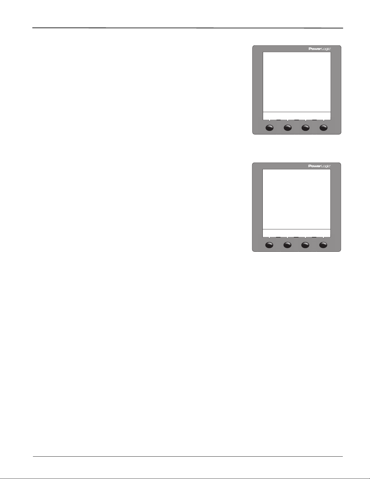
Power Meter Display
The power meter is equipped with a large, back-lit liquid crystal display (LCD). It can
display up to five lines of information plus a sixth row of menu options. Figure 3–1 shows
the different parts of the power meter display.
Figure 3– 1: Power Meter Display
A. Type of measurement
B. Screen title
C. Alarm indicator
D. Maintenance icon
E. Bar chart (%)
F. Units (A, V, etc.)
G. Display more menu items
H. Menu item
I. Selected menu indicator
J. Button
K. Return to previous menu
L. Values
M. Phase
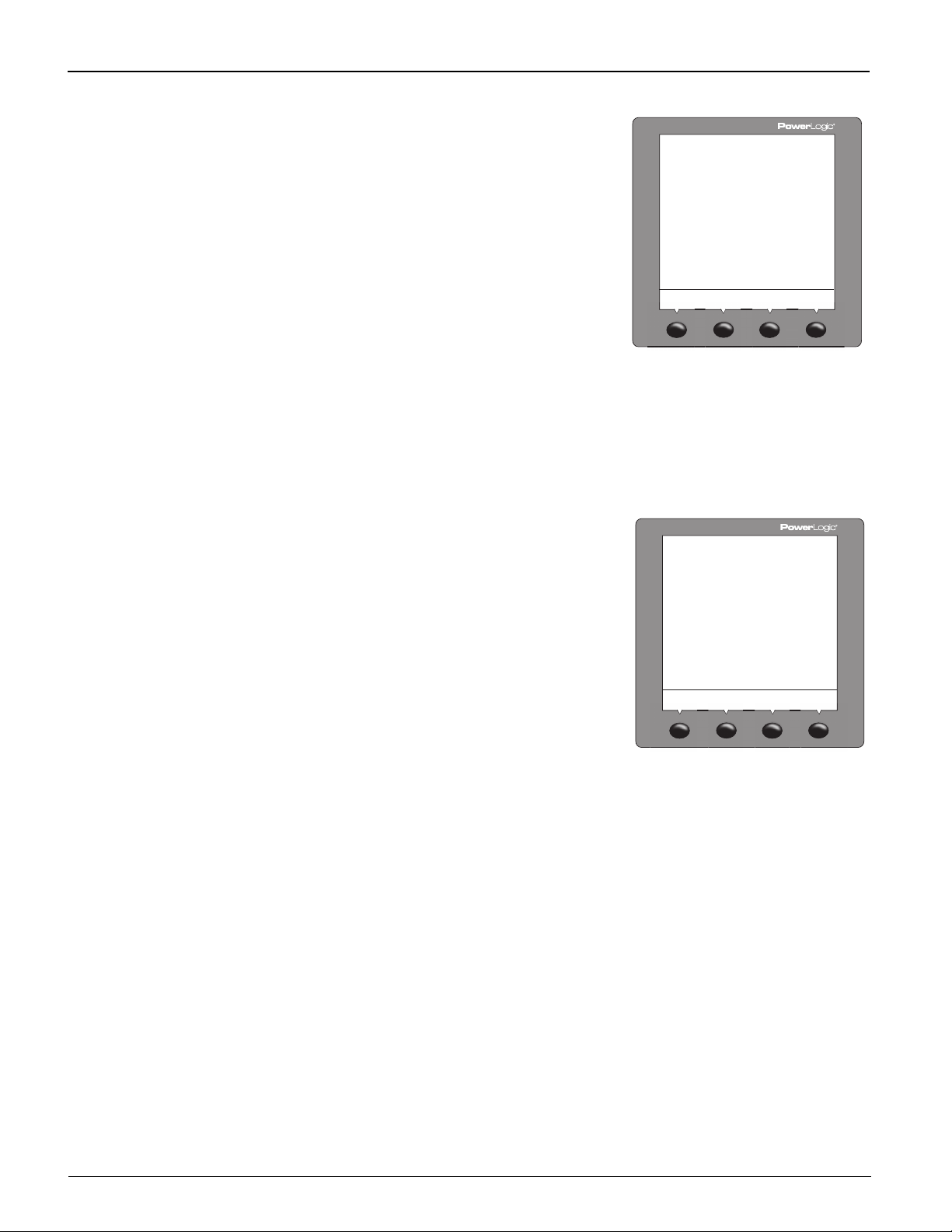
How the Buttons Work
The buttons are used to select menu items, display more menu items in a menu list, and
return to previous menus. A menu item appears over one of the four buttons. Pressing a
button selects the menu item and displays the menu item’s screen. When you have
reached the highest menu level, a black triangle appears beneath the selected menu item.
To return to the previous menu level, press the button below
items in a menu list, press the button below
NOTE: Each time you read “press” in this manual, press and release the appropriate button
beneath the menu item. For example, if you are asked to “Press PHASE,” you would press
the button below the PHASE menu item.
###: (see Figure 3 – 1).
1;. To scroll through the menu
Changing Values
When a value is selected, it flashes to indicate that it can be modified. A value is changed
by doing the following:
Menu Overview
• Press + (plus) or - (minus) to change numbers or scroll through available options.
• If you are entering more than a single-digit number, press <-- to move to the next
higher numeric position.
• To save your changes and move to the next field, press OK.
Figure 3–2 on page 12, shows the first two levels of the power meter menu. Level 1
contains all of the top level menu items. Selecting a Level 1 menu item takes you to the
corresponding Level 2 menu items. Additional menu levels may be provided, depending on
the specific meter features and options.
NOTE: Press ###: to scroll through all menu items on a given level.
© 2011 Schneider Electric. All Rights Reserved.
11

TM
PHASE I - DMD UNBAL
PWR (PQS) PHASE P - DMD
TRUE DISPL
V L-L (U) V L-N (V) I
MINMX AMPS (I) VOLTS (U-V) UNBAL PWR (PQS) PF HZ (F) THD V THD I
ACTIV HIST
DATE TIME LANG COMMS (COM) METER ALARM I/O PASSW TIMER ADVAN
AMPS (I)
VOLTS (U-V)
PWR (PQS)
ENERG (E)
PF
HZ (F)
THD
MINMX
ALARM
I/O
RESET
SETUP
DIAG
HARM
METER ENERG (E) DMD MINMX MODE TIMER
CONTR
MAINT
TIMER
PM8M2222
COMM1
COMM2
PM8RD
D OUT D IN A OUT A IN
METER REG CLOCK
1
3
2
D OUT [Digital KY Out]
D IN [Digital In]
A OUT [Analog Out]
A IN [Analog In]
PM8M2222
PM8M2222, PM8M26, and PM8M22
4
4
4
1
V L-L (U) V L-N (V) I
V L-L (U) V L-N (V)
Wh VAh VARh INC
LEVEL 1
LEVEL 2
PowerLogic
Series 800 Power Meter 63230-500-225A2
Chapter 3—Operation 3/2011
Figure 3–2: Abbreviated List of PM800 Menu Items in IEEE (IEC) Mode
© 2011 Schneider Electric. All Rights Reserved.
➀ Available on the PM810 only when an optional Power Meter Logging Module (PM810LOG) is installed. Available on all other PM800 Series models.
➁ Available with some models.
➂ Both IEC and IEEE modes are available. Depending on the mode selected, menu labels will be different. See “Display Mode Change” on page 24 to select the
desired mode.
➃ The PM810 has a volatile clock. The PM810 with an optional Power Meter Logging Module (PM810LOG), and all other PM800 Series models, have a non-volatile
clock.
12

63230-500-225A2 PowerLogicTM Series 800 Power Meter
!
!
""!
PLSD110218
3/2011 Chapter 3—Operation
Power Meter Setup
Power meter setup is typically performed by using the meter’s front panel display. To
configure a power meter without a display, you will need a means of communication
between the power meter and your computer. Additionally, you will need to install
PowerLogic Meter Configuration Software or PowerLogic ION Setup Software on your
computer. These can be downloaded from the Schneider’s www.Schneider-Electric.com
website.
Power meter setup is performed through the meter’s maintenance (MAINT) option. Refer to
Figure 3–2 on page 12. Setup features may be programmed individually or in any order. To
access the Setup features, follow these steps:
SETUP MODE Access
1. Press ###: to scroll through the Level 1 menu until you see MAINT.
2. Press MAINT.
3. Press SETUP.
4. Enter your password, then press OK. The SETUP MODE screen will be displayed.
NOTE: The default password is 0000.
5. Press
After programming a feature, you may continue through the remaining features by returning
to the SETUP MODE screen and pressing
Once you have selected the correct options for each setup parameter, press
SAVE CHANGES? prompt appears, then press YES. The meter will reset, briefly display
the meter info screen, then automatically return to the main screen.
Use the menu provided in Figure 3– 2 on page 12 to locate the setup features described in
the following topics:
###: to scroll through the setup features and select the one to be programmed.
###: to scroll to additional features.
1; until the
DATE Setup
1. Perform steps 1 through 5 of the SETUP MODE
Access procedure on page 11.
2. Press
3. Press DATE.
4. Enter the MONTH number.
5. Press OK.
6. Enter the DAY number.
7. Press OK.
8. Enter the YEAR number.
9. Press OK.
10. Select how the date is displayed: M/D/Y,
11. Press OK to return to the SETUP MODE
12. Press
13. To verify the new settings, press MAINT >
NOTE: The clock in the PM810 is volatile. Each time the meter resets, the PM810 returns
to the default clock date/time of 12:00 AM 01-01-1980. See “Date and Time Settings” on
page 69 for more information. All other PM800 Series meters have a non-volatile clock
which maintains the current date and time when the meter is reset.
###: until DATE is visible.
Y/M/D, or D/M/Y).
screen.
1; to return to the main screen.
DIAG > CLOCK.
© 2011 Schneider Electric. All Rights Reserved.
13

TM
#$
%&
'()
PLSD110227
PLSD110103
PowerLogic
Chapter 3—Operation 3/2011
Series 800 Power Meter 63230-500-225A2
TIME Setup
1. Perform steps 1 through 5 of the SETUP MODE
Access procedure on page 11.
2. Press
3. Press TIME.
4. Enter the HOUR.
5. Press OK.
6. Enter the MIN (minutes).
7. Press OK.
8. Enter the SEC (seconds).
9. Press OK.
10. Select how the time is displayed: 24H or
11. Press OK to return to the SETUP MODE
12. Press
13. To verify the new settings, press MAINT >
NOTE: The clock in the PM810 is volatile. Each time the meter resets, the PM810 returns
to the default clock date/time of 12:00 AM 01-01-1980. See “Date and Time Settings” on
page 69 for more information. All other PM800 Series meters have a non-volatile clock,
which maintains the current date and time when the meter is reset.
###: until TIME is visible.
AM/PM.
screen.
1; to return to the main screen.
DIAG > CLOCK.
LANG (Language) Setup
1. Perform steps 1 through 5 of the SETUP MODE
Access procedure on page 11.
2. Press
3. Press LANG.
4. Select the language: ENGL (English), FREN
5. Press OK.
6. At the SETUP MODE screen, continue
7. Press YES to save the changes.
###: until LANG is visible.
(French), SPAN (Spanish), GERMN (German),
or RUSSN (Russian).
programming additional setup features or
1; until you are asked to save changes.
press
*++
+*
14
© 2011 Schneider Electric. All Rights Reserved.

63230-500-225A2 PowerLogicTM Series 800 Power Meter
,-(
.
PLSD110100
PLSD110106
3/2011 Chapter 3—Operation
COMMS (Communications) Setup
NOTE: If you are using PowerLogic software to set up the power meter, it is recommended
you set up the communications features first.
Refer to Table 3-1 for the meter’s default settings.
Table 3– 1: Communications Default Settings
Communications Setting Default
Protocol MB.RTU (Modbus RTU)
Address 1
Baud Rate 9600
Parity Even
The same procedure is used to program the settings for the COMMS, COMM 1, and
COMM 2 options.
1. Perform steps 1 through 5 of the SETUP MODE
Access procedure on page 11.
2. Press
3. Press COMMS (communications).
4. Select the required protocol: MB.RTU (Modbus
5. Press OK.
6. Enter the ADDR (power meter address).
7. Press OK.
8. Select the BAUD (baud rate).
9. Press OK.
10. Select the parity: EVEN, ODD, or NONE.
11. Press OK.
12. At the SETUP MODE screen, continue
13. Press YES to save the changes.
###: until COMMS (communications)
is visible.
RTU), Jbus, MB. A.8 (Modbus ASCII 8 bits),
MB. A.7 (Modbus ASCII 7 bits).
programming additional setup features or
1; until you are asked to save changes.
press
METER Setup
© 2011 Schneider Electric. All Rights Reserved.
CTs Setup
This feature allows the user to configure the CTs, PTs, system frequency, and system
wiring method.
1. Perform steps 1 through 5 of the SETUP MODE
Access procedure on page 11.
2. Press
3. Press METER.
4. Press CT.
5. Enter the PRIM (CT primary) number.
6. Press OK.
7. Enter the SEC. (CT secondary) number.
8. Press OK.
9. At the SETUP MODE screen, continue
10. Press YES to save the changes.
###: until METER is visible.
programming additional setup features or
1; until you are asked to save changes.
press
15

TM
*
/
PLSD110112
PLSD110109
PLSD110324
PowerLogic
Chapter 3—Operation 3/2011
Series 800 Power Meter 63230-500-225A2
PTs Setup
1. Perform steps 1 through 5 of the SETUP MODE
Access procedure on page 11.
2. Press
3. Press METER.
4. Press PT.
5. Enter the SCALE value: x1, x10, x100, NO PT
6. Press OK.
7. Enter the PRIM (primary) value.
8. Press OK.
9. Enter the SEC. (secondary) value.
10. Press OK.
11. At the SETUP MODE screen, continue
12. Press YES to save the changes.
###: until METER is visible.
(for direct connect).
programming additional setup features or
1; until you are asked to save changes.
press
HZ (System Frequency) Setup
1. Perform steps 1 through 5 of the SETUP MODE
Access procedure on page 11.
2. Press
3. Press METER.
4. Press
5. Press HZ.
6. Select the frequency.
7. Press OK.
8. At the SETUP MODE screen, continue
9. Press YES to save the changes.
###: until METER is visible.
###: until HZ is visible.
programming additional setup features or
1; until you are asked to save changes.
press
!0)#1(#$2
3
04
SYS (System Type) Setup
1. Perform steps 1 through 5 of the SETUP MODE
Access procedure on page 11.
2. Press
3. Press METER.
4. Press ###: until SYS is visible.
5. Press SYS.
6. Select your system (SYS) type (D) based on
7. Press OK.
8. At the SETUP MODE screen, continue
9. Press YES to save the changes.
###: until METER is visible.
the number of wires (A), the number of CTs (B),
and the number of voltage connections (either
direct connect or with PT) (C).
programming additional setup features or
1; until you are asked to save changes.
press
5!
A
B
C
D
6
!
16
© 2011 Schneider Electric. All Rights Reserved.
63230-500-225A2 PowerLogicTM Series 800 Power Meter
..
+
*
*
PLSD110212
PLSD110311
3/2011 Chapter 3—Operation
ALARM (Alarms) Setup
There is an extensive list of meter error conditions
which can be monitored and cause an alarm.
1. Perform steps 1 through 5 of the SETUP MODE
Access procedure on page 11.
2. Press
3. Press ALARM.
4. Press
5. Press EDIT.
6. Select to ENABL (enable) or DISAB (disable)
7. Press OK.
8. Select the PR (priority): NONE, HIGH, MED, or
9. Press OK.
10. Select how the alarm values are displayed:
11. Enter the PU VALUE (pick-up value).
12. Press OK.
13. Enter the PU DELAY (pick-up delay).
14. Press OK.
15. Enter the DO VALUE (drop-out value).
16. Press OK.
17. Enter the DO DELAY (drop-out delay).
18. Press OK.
19. Press
20. Press
21. At the SETUP MODE screen, continue
22. Press YES to save the changes.
###: until ALARM is visible.
<- or -> to select the alarm option you
want to edit.
the alarm.
LOW.
ABSOL (absolute value) or RELAT (percentage
relative to the running average).
1; to return to the alarm summary
screen.
1; to return to the SETUP MODE screen.
programming additional setup features or
1; until you are asked to save changes.
press
..
+
*!
+
*!
© 2011 Schneider Electric. All Rights Reserved.
17

TM
PLSD110221
PLSD110224
PowerLogic
Chapter 3—Operation 3/2011
Series 800 Power Meter 63230-500-225A2
I/O (Input/Output) Setup
1. Perform steps 1 through 5 of the SETUP MODE
Access procedure on page 11.
2. Press
3. Press I/O.
4. Press D OUT for digital output or D IN for digital
5. Press EDIT.
6. Select the I/O mode based on the I/O type and
7. Depending on the mode selected, the power
8. Press OK.
9. Select EXT. (externally controlled via
10. Press
11. At the SETUP MODE screen, continue
12. Press YES to save the changes.
###: until I/O is visible.
input, or press A OUT for analog output or A IN
for analog input. Use the ###: button to scroll
through these selections.
NOTE: Analog inputs and outputs are available
only with the PM8222 option module.
the user selected mode: NORM., LATCH,
TIMED, PULSE, or END OF.
meter will prompt you to enter the pulse weight,
timer, and control.
communications) or ALARM (controlled by an
alarm).
1; to return to the SETUP MODE screen.
programming additional setup features or
1; until you are asked to save changes.
press
!
*
/
PASSW (Password) Setup
1. Perform steps 1 through 5 of the SETUP MODE
2. Press
3. Press PASSW.
4. Enter the SETUP password.
5. Press OK.
6. Enter the DIAG (diagnostics) password.
7. Press OK.
8. Enter the ENERG (energy reset) password.
9. Press OK.
10. Enter the MN/MX (minimum/maximum reset)
11. Press OK.
12. At the SETUP MODE screen, continue
13. Press YES to save the changes.
Access procedure on page 11.
###: until PASSW (password) is visible.
password.
programming additional setup features or
1; until you are asked to save changes.
press
6
+
+
"/
18
© 2011 Schneider Electric. All Rights Reserved.

63230-500-225A2 PowerLogicTM Series 800 Power Meter
.+
5
PLSD110257
PLSD110203
3/2011 Chapter 3—Operation
TIMER (Operating Time Threshold) Setup
1. Perform steps 1 through 5 of the SETUP MODE
Access procedure on page 11.
2. Press
###: until TIMER is visible.
3. Press TIMER.
4. Enter the 3-phase current average.
NOTE: The power meter begins counting the
operating time whenever the readings are equal
to or above the average.
5. Press OK.
6. At the SETUP MODE screen, continue
programming additional setup features or
1; until you are asked to save changes.
press
7. Press YES to save the changes.
ADVAN (Advanced) Power Meter Setup Features
The Advanced Feature set contains several items which need to be programmed. To
access these features, follow these steps:
After programming a feature, you may continue through the remaining features by returning
to the SETUP MODE screen and pressing ###: to scroll to additional features.
Once you have selected the correct options for each setup parameter, press
SAVE CHANGES? prompt appears, then press YES. The meter will reset, briefly display
the meter info screen, then automatically return to the main screen.
1;
until the
ROT (Phase Rotation) Setup
1. Perform steps 1 through 5 of the SETUP MODE
Access procedure on page 11.
2. Press
3. Press ADVAN.
4. Press ###: until ROT (phase rotation) is visible.
5. Press ROT.
6. Select the phase rotation: ABC or CBA.
7. Press OK.
8. At the SETUP MODE screen, continue
9. Press YES to save the changes.
###: until ADVAN (advanced setup) is
visible.
programming additional setup features or
1; until you are asked to save changes.
press
'7-78'
© 2011 Schneider Electric. All Rights Reserved.
19

TM
+!
.*
PLSD110197
PLSD110206
PLSD110209
PowerLogic
Chapter 3—Operation 3/2011
Series 800 Power Meter 63230-500-225A2
E-INC (Incremental Energy Interval) Setup
1. Perform steps 1 through 5 of the SETUP MODE
Access procedure on page 11.
2. Press
###: until ADVAN (advanced setup) is
visible.
3. Press ADVAN.
4. Press
###: until E-INC (incremental energy) is
visible.
5. Press E-INC.
6. Enter the INTVL (interval). Range is 00 to 1440.
7. Press OK.
8. At the SETUP MODE screen, continue
programming additional setup features or
1; until you are asked to save changes.
press
9. Press YES to save the changes.
THD Calculation Setup
1. Perform steps 1 through 5 of the SETUP MODE
Access procedure on page 11.
2. Press
###: until ADVAN (advanced setup) is
visible.
3. Press ADVAN.
4. Press
###: until THD is visible.
5. Press THD.
6. Select the THD calculation: FUND or RMS.
7. Press OK.
8. At the SETUP MODE screen, continue
programming additional setup features or
1; until you are asked to save changes.
press
9. Press YES to save the changes.
-9$(9-78'
:(
VAR/PF Convention Setup
1. Perform steps 1 through 5 of the SETUP MODE
Access procedure on page 11.
2. Press
###: until ADVAN (advanced setup) is
visible.
3. Press ADVAN.
4. Press
###: until PF is visible.
5. Press PF.
6. Select the Var/PF convention: IEEE or IEC.
7. Press OK.
8. At the SETUP MODE screen, continue
programming additional setup features or
1; until you are asked to save changes.
press
9. Press YES to save the changes.
0';#78'
8###
20
© 2011 Schneider Electric. All Rights Reserved.

63230-500-225A2 PowerLogicTM Series 800 Power Meter
PLSD110200
* *+>
PLSD110215
PLSD110231
3/2011 Chapter 3—Operation
Lock Resets Setup
1. Perform steps 1 through 5 of the SETUP MODE
Access procedure on page 11.
2. Press
###: until ADVAN (advanced setup) is
visible.
9'$<#=#7=>
3. Press ADVAN.
4. Press
###: until LOCK is visible.
5. Press LOCK.
6. Select Y (yes) or N (no) to enable or disable
resets for PK.DMD, ENERG, MN/MX, and
METER.
!
+
?"@A
#7#)
7. Press OK.
8. At the SETUP MODE screen, continue
programming additional setup features or
1; until you are asked to save changes.
press
9. Press YES to save the changes.
Alarm Backlight Setup
1. Perform steps 1 through 5 of the SETUP MODE
Access procedure on page 11.
2. Press
3. Press ADVAN.
4. Press ###: until BLINK is visible.
5. Press BLINK.
6. Enter ON or OFF.
7. Press OK.
8. At the SETUP MODE screen, continue
9. Press YES to save the changes.
###: until ADVAN (advanced setup) is
visible.
programming additional setup features or
1; until you are asked to save changes.
press
Bar Graph Setup
© 2011 Schneider Electric. All Rights Reserved.
1. Perform steps 1 through 5 of the SETUP MODE
Access procedure on page 11.
2. Press
###: until ADVAN (advanced setup) is
visible.
3. Press ADVAN.
4. Press
###: until BARGR is visible.
5. Press BARGR.
6. Press AMPS or PWR.
7. Select AUTO or MAN. If MAN is selected, press
OK and enter the %CT*PT and KW (for PWR)
or the %CT and A (for AMPS).
8. Press OK.
9. At the SETUP MODE screen, continue
programming additional setup features or
1; until you are asked to save changes.
press
10. Press YES to save the changes.
-)B)-C=$-9#
6
21
TM
'D#)0+
.*
*
PLSD110232
PowerLogic
Chapter 3—Operation 3/2011
Series 800 Power Meter 63230-500-225A2
PQ Advanced Evaluation Setup
1. Perform steps 1 through 5 of the SETUP MODE
Access procedure on page 11.
2. Press
3. Press ADVAN.
4. Press
5. Press PQADV.
6. Select ON.
7. Press OK.
8. Change the nominal voltage (NOM V) value if
9. Press OK to return to the SETUP MODE
10. At the SETUP MODE screen, continue
11. Press YES to save your changes and reset the
###: until ADVAN (advanced setup) is
visible.
###: until PQADV is visible.
desired (the default is 230).
screen.
programming additional setup features or
1; until you are asked to save changes.
press
power meter.
4;-
.
Power Demand Configuration Setup
1. Perform steps 1 through 5 of the SETUP MODE
Access procedure on page 11.
2. Press
3. Press ADVAN.
4. Press ###: until DMD is visible.
5. Press DMD (P-DMD, I-DMD).
6. Select the demand configuration. Choices are
7. Press OK.
8. Enter the INTVL (interval) and press OK.
9. Enter the SUB-I (sub-interval) and press OK.
10. At the SETUP MODE screen, continue
11. Press YES to save the changes.
###: until ADVAN (advanced setup) is
visible.
COMMS, RCOMM, CLOCK, RCLCK, IENGY,
THERM, SLIDE, BLOCK, RBLCK, INPUT, and
RINPUT.
programming additional setup features or
1; until you are asked to save changes.
press
22
© 2011 Schneider Electric. All Rights Reserved.

63230-500-225A2 PowerLogicTM Series 800 Power Meter
>
!
PLSD110285
+!>
!
<.E
<.E
<6E
PLSD110280
3/2011 Chapter 3—Operation
Power Meter Resets
The Power Meter Resets Feature set contains several items. After resetting a feature, you
may continue through the remaining features by returning to the RESET MODE screen and
pressing
press 1; until the display returns to the main screen.
Initialize the Power Meter
Initializing the power meter resets the energy
readings, minimum/maximum values, and
operating times. To initialize the power meter,
follow these steps:
1. Press ###: to scroll through the Level 1 menu
2. Press MAINT.
3. Press RESET.
4. Press
5. Press METER.
6. Enter the password (the default is 0000).
7. Press YES to initialize the power meter and to
8. At the RESET MODE screen, continue
NOTE: We recommend initializing the power meter
after you make changes to any of the following:
CTs, PTs, frequency, or system type.
###: to scroll to additional features. Once you have reset the specific features,
until you see MAINT.
###: until METER is visible.
return to the RESET MODE screen.
resetting additional features or press
you return to the main screen.
1; until
Accumulated Energy Readings Reset
1. Press ###: to scroll through the Level 1 menu
until you see MAINT.
2. Press MAINT.
3. Press RESET.
4. Press
5. Press ENERG.
6. Enter the password (the default is 0000).
7. Press YES to reset the accumulated energy
###: until ENERG is visible.
readings and to return to the RESET MODE
screen.
© 2011 Schneider Electric. All Rights Reserved.
23

TM
PLSD110281
PLSD110282
0*>
4
PLSD110283
PowerLogic
Chapter 3—Operation 3/2011
Series 800 Power Meter 63230-500-225A2
Accumulated Demand Readings Reset
1. Press ###: to scroll through the Level 1 menu
until you see MAINT.
2. Press MAINT.
3. Press RESET.
4. Press
5. Press DMD.
6. Enter the password (the default is 0000).
7. Press YES to reset the accumulated demand
###: until DMD is visible.
readings and to return to the RESET MODE
screen.
>
<6F<
<
<
!
<.F
Minimum/Maximum Values Reset
1. Press ###: to scroll through the Level 1 menu
until you see MAINT.
2. Press MAINT.
3. Press RESET.
4. Press
5. Press MINMX.
6. Enter the password (the default is 0000).
7. Press YES to reset the minimum/maximum
###: until MINMX is visible.
values and to return to the RESET MODE
screen.
"/>
!
Display Mode Change
1. Press ###: to scroll through the Level 1 menu
until you see MAINT.
2. Press MAINT.
3. Press RESET.
4. Press
5. Press MODE.
6. Press IEEE (default for Square D branded
NOTE: Resetting the mode changes the menu
labels, power factor conventions, and THD
calculations to match the standard mode selected.
To customize the mode changes, see the register
list.
###: until MODE is visible.
power meters) or IEC (default for Schneider
Electric branded power meters) depending on
the operating mode you want to use.
24
© 2011 Schneider Electric. All Rights Reserved.
 Loading...