


Schneider Electric AP9921XS, AP9921X User Manual

Installation
Battery Management
System
AP9921X
AP9921XS


Contents
Overview...........................................................................1
System Information. . . . . . . . . . . . . . . . . . . . . . . . . . . . . . . . . . . . . . . .1
Inventory (AP9921X) . . . . . . . . . . . . . . . . . . . . . . . . . . . . . . . . . . 1
Inventory (AP9921XS) . . . . . . . . . . . . . . . . . . . . . . . . . . . . . . . . . 1
Additional options . . . . . . . . . . . . . . . . . . . . . . . . . . . . . . . . . . . . 2
Additional documentation . . . . . . . . . . . . . . . . . . . . . . . . . . . . . . 2
Wire harness installation . . . . . . . . . . . . . . . . . . . . . . . . . . . . . . . 2
Receiving inspection . . . . . . . . . . . . . . . . . . . . . . . . . . . . . . . . . . 2
Please recycle . . . . . . . . . . . . . . . . . . . . . . . . . . . . . . . . . . . . . . . 2
Safety Information. . . . . . . . . . . . . . . . . . . . . . . . . . . . . . . . . . . . . . . . .3
Lockout/Tagout the UPS . . . . . . . . . . . . . . . . . . . . . . . . . . . . . . . 3
Master and Expansion Units . . . . . . . . . . . . . . . . . . . . . . . . . . . . . . . .4
Front panel—master unit (AP9921X) . . . . . . . . . . . . . . . . . . . . . . 4
Rear panel—master unit (AP9921X) . . . . . . . . . . . . . . . . . . . . . . . 5
Front panel—expansion unit (AP9921XS) . . . . . . . . . . . . . . . . . . . 6
Rear panel—expansion unit (AP9921XS) . . . . . . . . . . . . . . . . . . . 6
Installation........................................................................7
Install the Unit . . . . . . . . . . . . . . . . . . . . . . . . . . . . . . . . . . . . . . . . . . . .7
Overview . . . . . . . . . . . . . . . . . . . . . . . . . . . . . . . . . . . . . . . . . . . 7
Installation guidelines . . . . . . . . . . . . . . . . . . . . . . . . . . . . . . . . . 7
Install the unit using rubber feet . . . . . . . . . . . . . . . . . . . . . . . . . 7
Mount the unit on the wall or door of the battery cabinet . . . . . . . 7
Connect the ground wire . . . . . . . . . . . . . . . . . . . . . . . . . . . . . . . 8
Configure the DIP Switches . . . . . . . . . . . . . . . . . . . . . . . . . . . . . . . . .9
Install the Temperature Sensor Assembly . . . . . . . . . . . . . . . . . . . .10
Install the Current Sensor. . . . . . . . . . . . . . . . . . . . . . . . . . . . . . . . . .11
Connect Multiple Units . . . . . . . . . . . . . . . . . . . . . . . . . . . . . . . . . . . .13
Battery Management System — Installation i

Quick Configuration (AP9921X only)........................... 14
Overview . . . . . . . . . . . . . . . . . . . . . . . . . . . . . . . . . . . . . . . . . . . . . . . 14
TCP/IP Configuration Methods . . . . . . . . . . . . . . . . . . . . . . . . . . . . . 14
Device IP Configuration Wizard . . . . . . . . . . . . . . . . . . . . . . . . .14
BOOTP & DHCP configuration . . . . . . . . . . . . . . . . . . . . . . . . . .15
Local access to the control console . . . . . . . . . . . . . . . . . . . . . .16
Remote access to the control console . . . . . . . . . . . . . . . . . . . .17
Control console . . . . . . . . . . . . . . . . . . . . . . . . . . . . . . . . . . . . .17
Configure Modbus . . . . . . . . . . . . . . . . . . . . . . . . . . . . . . . . . . . . . . . 18
Modbus pin-out and baud rate . . . . . . . . . . . . . . . . . . . . . . . . . .18
Access a Configured Unit . . . . . . . . . . . . . . . . . . . . . . . . . . . . . . . . . 19
Overview . . . . . . . . . . . . . . . . . . . . . . . . . . . . . . . . . . . . . . . . . .19
Web interface . . . . . . . . . . . . . . . . . . . . . . . . . . . . . . . . . . . . . . .19
Telnet . . . . . . . . . . . . . . . . . . . . . . . . . . . . . . . . . . . . . . . . . . . . .19
Simple Network Management Protocol (SNMP) . . . . . . . . . . . . . .20
FTP and SCP . . . . . . . . . . . . . . . . . . . . . . . . . . . . . . . . . . . . . . .20
Recover From a Lost Password . . . . . . . . . . . . . . . . . . . . . . . . . . . . 21
Upgrade Firmware . . . . . . . . . . . . . . . . . . . . . . . . . . . . . . . . . . . . . . . 21
Specifications ................................................................ 22
ii Battery Management System — Installation

Overview
System Information
The American Power Conversion (APC®) Battery Management System connects to one of the
following:
• A single UPS with one string of up to 244 lead-acid batteries or 375 nickel-cadmium batteries.
• A single UPS with two strings of up to 244 lead-acid batteries or 256 nickel-cadmium batteries.
The system provides battery management for nominal 2 V, 4 V, 8 V, or 12 V lead-acid batteries; or 1.2 V
or 2.4 V nickel-cadmium batteries. A system is comprised of one AP9921X master unit and up to seven
AP9921XS expansion units. Each unit supports up to 64 batteries.
For more information on the features and capabilities of the Battery Management System, see
the initial sections of the Battery Management System User’s Guide, which is available on
the supplied Utility CD.
Note: Do not turn on the power to the system until the DIP switches are configured and the
wire harnesses are connected to the Battery Management System and the batteries.
Inventory (AP9921X)
Quantity Item
1 Battery Management master unit (with internal Network Management capability)
1 Configuration cable (APC part number 940-0103)
1 Temperature sensor assembly
1 Ground wire assembly
2 Brackets for wall- or cabinet-mounting (with 8 pan-head screws)
6 Rubber feet (with alcohol pads)
Inventory (AP9921XS)
Quantity Item
1 Battery Management expansion unit
2 Brackets for wall- or cabinet-mounting (with 8 pan-head screws)
1 Ground wire assembly
1 Expansion cable
6 Rubber feet (with alcohol pads)
1Battery Management System — Installation

Additional options
The following options are available for use with the Battery Management System:
• Additional expansion units (AP9921XS)
• 5-foot battery wire harness (AP9924)
• 25-foot battery wire harness (AP9925)
• 50-foot battery wire harness (AP9926)
• 100-foot battery wire harness (AP9927)
• Current sensor kit (AP9920CS)
• 2000-amp current sensor kit (AP9920CS2000)
• Alarm beacon (AP9324)
Additional documentation
The Battery Management System User’s Guide is available on the supplied CD and on the APC Web
site, www.apc.com.
The User’s Guide contains additional information about the following topics related to the unit:
• Management interfaces
• User accounts
• Customizing setup
• Security
• The Device IP Configuration Wizard
• File transfers
• The Security Wizard
Wire harness installation
Wire harnesses are required for connecting batteries to the Battery Management System. Purchase the
harnesses separately and install them according to the instructions in the installation manuals provided
with the wire harnesses.
Receiving inspection
Inspect the package and contents for shipping damage, and make sure that all parts were sent. Report any
damage immediately to the shipping agent. Report missing contents, damage, or other problems
immediately to APC or your APC reseller.
Please recycle
The shipping materials are recyclable. Save them for later use, or dispose of them
appropriately.
Battery Management System — Installation2

Safety Information
Electrical Hazard: Risk of electric shock—battery cabinets contain potentially lethal
voltages! Batteries are energized even when AC power has been disconnected.
All electrical equipment must be rated for the voltage of your Battery Management
System.
Warning: Only qualified personnel, trained in battery operation and safety, may install
the harnesses. Keep unauthorized personnel away from the batteries.
When installing the Battery Management System:
• Cover the batteries with an electrical insulating blanket before installing the harnesses.
• Wear rubber gloves, rubber boots, and safety goggles.
• Use double-insulated tools.
• Do not short-circuit the battery terminals; this could cause the batteries to explode.
• Do not lay tools or metal parts on top of the batteries or near the cable lugs.
• Remove watches, rings, and other metal objects.
• For the UPS and switch gear, use lock-out/tag-out safety procedures (which remove access to a
device and physically label the device as intentionally out of service) before working on the
batteries.
• Use only cables supplied by APC unless otherwise indicated.
• Avoid skin contact with battery components, such as electrolyte.
Lockout/Tagout the UPS
Note: Lockout/Tagout safety procedures remove access to a device and physically label the
device as intentionally out of service.
Before installing the Battery Management System, use lockout/tagout safety procedures for the UPS and
any attached equipment, such as high-voltage power supplies. If possible, disconnect the main output
lead from the battery string to the load.
Electrical Hazard:
from the main load. Use caution when working with the batteries.
Each battery should be treated as though the entire string voltage were present at its
terminals.
Voltage is present in the battery cabinet even after disconnecting
3Battery Management System — Installation
Master and Expansion Units
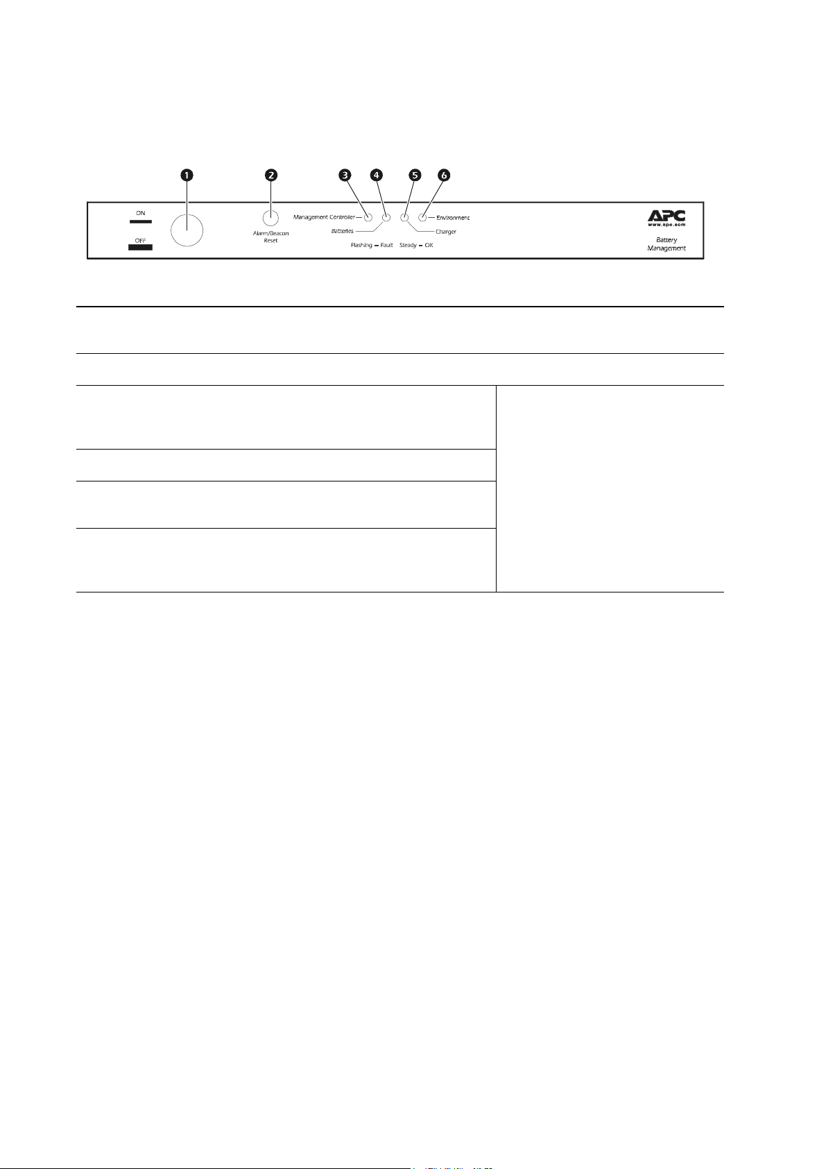
Front panel—master unit (AP9921X)
Item Description LED Behavior
ON/OFF Button Used to enable or disable the unit. The unit is “On” when the button is
1
pressed in.
Alarm/Beacon Reset Resets the alarm or beacon if either is active.
2
mph0238b
Management Controller LED Indicates the status of the Battery
3
Management System and its
connections.
Batteries LED Indicates the status of the batteries.
4
Charger LED Indicates the status of the charger’s
5
(UPS) voltage or ripple current.
Environment LED Indicates the status of the battery
6
environment (temperature) or
external sensors.
Off: The Battery Management System
is not receiving power or the LED is
not functioning properly.
Solid: The associated status is OK.
Flashing: The associated status is
outside its configured limits and is in
an alarm condition.
Battery Management System — Installation4

Rear panel—master unit (AP9921X)
Base-T Port
10=Green
100=Orange
Item Description
1 Ground Ground wire connection.
Battery harness connector (B) Connects the Battery Management System to the battery harness.
2
Network/Ethernet port Connects to the network using a CAT5 cable.
3
4 Link RX/TX LED Indicates the status of the network connection.
• Off : The unit is not receiving power, or the LED is not functioning
properly.
• Flashing: The unit is receiving data packets from or sending data
packets to the network. Flashing orange indicates a transfer speed of
10 Mb, flashing green indicates a transfer speed of 100 Mb.
Status LED Indicates the status of traffic over the network connection.
5
• Off: The unit is not receiving power, or the Battery Management
System is not functioning properly.
• Solid green: The unit has valid TCP/IP settings.
• Flashing green: The unit does not have valid TCP/IP settings.
• Solid orange: The unit’s Management Card has detected a hardware
failure. Contact APC Customer Support.
• Flashing orange: The unit is making BOOTP requests.
• Alternately flashing orange and green: If the LED is alternately
flashing slowly, the Battery Management System is making DHCP
requests. If the LED is alternately flashing rapidly, the Battery
Management System is starting up.
A-Link port (2) Reserved for future use.
6
Expansion Bus ports (2)
7
Powerview port Reserved for future use.
8
Beacon Connects to optional alarm beacon (APC part number AP9324).
9
Alarm Contact port
:
Settings (DIP Switch)
;
Remote LEDs port
<
Temperature sensors port Connects the temperature sensor assembly (940-0089).
=
RS-232/485 port Connects to Modbus and configures the network card.
>
Current sensor ports (A and B)
?
Battery harness connector (A)
@
Unit #
A
Used to cascade one to seven expansion units (AP9921XS) to a single
master unit (AP9921X). See “Connect Multiple Units” on page 13.
Used to connect external equipment such as an automatic dialer to
signal an alarm. This is a summary alarm.
Configures the unit address and termination resistors. (See “Configure
the DIP Switches” on page 9).
Connects the unit to the remote alarm reset, or two auxiliary
environmental inputs.
Connects the Battery Management System to the charge/discharge
string current sensors.
Connects the Battery Management System to the battery harness and to
unit power.
Use this space to write the number of the unit for easy identification
and for setting the DIP switches.
5Battery Management System — Installation
 Loading...