


Schneider Electric MG350V Installation Instructions
Installation Instruction
Electrical Connections
Power input, running with full load |
MGF350V-24FP, MG350V-24M, |
24 Vac, ±20% (Class 2 power supply), 50/60 Hz, 7.2 VA, 20 … |
|
MGF350V-24MP |
29 Vdc, 3.5 W |
|
|
|
|
MG350V-24F |
24 Vac, ±20% (Class 2 power supply), 50/60 Hz, 5 VA, 20 … 29 |
|
|
Vdc, 3.5 W |
|
|
|
Power input, holding |
MGF350V-24FP, MG350V-24M, |
24 Vac, ±20% (Class 2 power supply), 50/60 Hz, 1.2 VA (24FP |
|
MGF350V-24MP |
0.7W, 24M 0.4W, 24MP 0.5W) |
|
|
|
|
MG350V-24F |
Actuator is unpowered when it is holding |
|
|
|
Internal power supply type |
MGF350V-24FP, MG350V-24M, |
half wave |
|
MGF350V-24MP |
|
|
|
|
|
MG350V-24F |
full wave |
|
|
|
Input signal impedance |
MG350V-24M and MGF350V-24MP |
2 … 10 Vdc and 0 … 10 Vdc >100 kOhms |
(MG350V-24M, MGF350V-24MP) |
|
|
|
|
|
|
MGF350V-24MP |
4 … 20 mA, 500 Ohms |
|
|
|
Input Signal Auto Calibration |
Automatic span calibration to precisely match the stroke length of the valve (with a minimum stroke of |
|
(MGF350V-24FP, MG350V-24M, |
1/8” (3.2 mm) and a maximum stroke of 21/32” (16.5 mm). |
|
MGF350V-24MP) |
|
|
|
|
|
Floating Control Signal |
SPST center off (floating) control contacts or one or two SPST control contacts, minimum rating of |
|
(MG350V-24F, MGF350V-24FP) |
250 mA at 24 V or one or two triacs must be able to switch 250 mA at 24 Vac, |
|
|
1,100 Ohms input impedance |
|
|
|
|
Floating Input Signal Minimum Pulse |
100 msec |
|
Width (MG350V-24F) |
|
|
|
|
|
Position Feedback Output Signal |
2 … 10 Vdc and 0 … 5 Vdc, 0.5 mA (field selectable) |
|
(MGF350V-24FP, MGF350V-24MP) |
|
|
|
|
|
Conduit Connection |
Removable 1/2” conduit opening plate |
|
|
|
|
Electrical Connections |
Removable terminal block, AWG 12 … 24, meets the requirements of cUL without the need of an |
|
|
electrical earth ground connection |
|
|
|
|
Mechanical
Linkage |
Linkage for 1/2” … 2” VB-7000 and 1/2” … 1-1/4” obsolete VB-9000 Globe Valves included with actuator |
|
|
Manual Override |
3 mm hex wrench (not included with actuator), “tee” handle style recommended |
|
|
Mechanical Valve Position Indicator |
Graduated position indicator showing open to close with end point indicators |
|
|
Electrical Valve Status Indication |
Tri-color LED status indication for motion indication, calibration, and alarm notification |
|
MG350V-24F does not include the calibration and alarm indication |
|
|
Speed |
MG350V-24 and MG350V-24M: 0.295” (7.5 mm) per minute |
|
|
|
MGF350-24FP and MGF350V-24MP: 0.59” (15 mm) per minute |
|
|
Force |
MG350V-24F and MG350V-24M: 78 lbf (350 N) force |
|
|
|
MGF350-24FP and MGF350V-24MP: 67 lbf (300 N) force |
|
|
Enclosure |
Plenum rated per UL 2043 |
|
|
Yoke |
Rugged die cast aluminum |
|
|
Weight |
1.6 lbs. |
|
|
Environmental
Operating Temperature Range |
For fluid temperatures up to 266 °F (130 °C): 23 |
… 131 °F (-5 … 55 °C) |
|
|
For fluid temperatures up to 281 °F (138 °C): |
23 |
… 127 °F (-5 … 53 °C) |
|
For fluid temperatures up to 340 °F (171 °C): |
23 |
… 115 °F (-5 … 46 °C) |
|
For fluid temperatures up to 400 °F (204 °C): |
23 |
… 102 °F (-5 … 39 °C) |
|
|
|
|
Shipping and Storage Temperature |
-40 … 158 ˚F (-40 … 70 ˚C) |
|
|
Range |
|
|
|
|
|
|
|
Operating Humidity Range |
5 … 95% non condensing |
|
|
|
|
||
Location |
NEMA 2 (IP 53) with proper mounting orientation |
||
|
|
|
|
Noise Level |
≤30 dB (A) @ 1 meter |
|
|
|
|
|
|
© 2017 Schneider Electric. All rights reserved. All trademarks are owned by Schneider Electric Industries SAS or its affiliated companies. |
February, 2019 tc |
Document Number: F-27852-11 |
|

Installation Instruction
IP51 and NEMA Type 2 Allowable Mounting Orientation |
IP53 and NEMA Type 2 Allowable Mounting Orientation |
||
|
0 |
|
0 |
85° |
85° |
60° |
60° |
Wiring
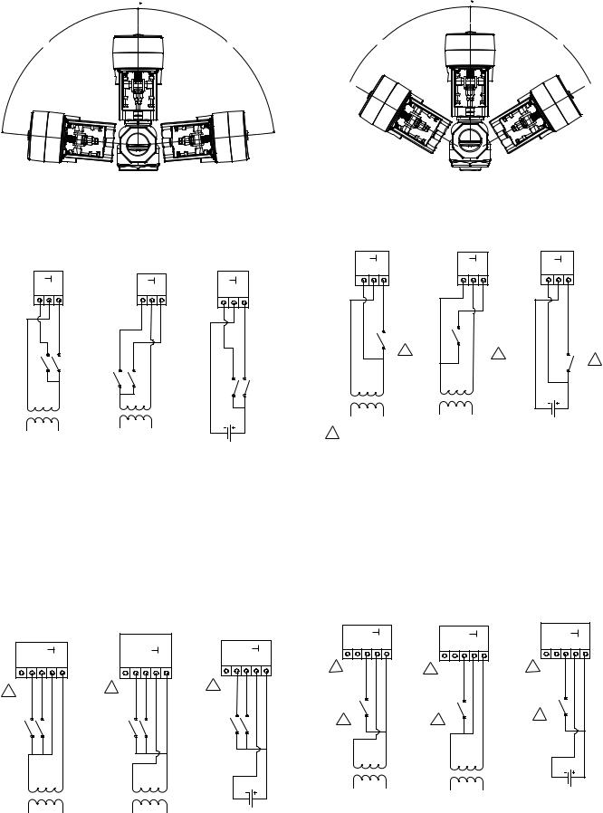
MG350V-24F Two Position (On/Off) Wiring
MG350V-24F Three Wire Floating Wiring |
24 VAC Two |
24 VAC Two |
24 VDC Two |
||
Position Sourcing |
Position Sinking |
Position Sourcing |
|||
24 VAC |
24 VAC |
|
24 VDC |
|
|
Floating Sourcing |
Floating Sinking |
Floating Sourcing |
|
|
|
|
<![if ! IE]> <![endif]>Y1 24 Y2 |
|
<![if ! IE]> <![endif]>Y1 24 Y2 |
<![if ! IE]> <![endif]>Y1 24 Y2 |
24G |
24H |
24G |
24H |
|
|
|
|
24 Ref |
24 VDC |
MG350V-24F Terminals
|
<![if ! IE]> <![endif]>Y1 24 Y2 |
|
<![if ! IE]> <![endif]>Y1 24 Y2 |
|
<![if ! IE]> <![endif]>Y1 24 Y2 |
|
1 |
|
|
1 |
|
|
|
|
|
1 |
|
|
|
|
|
|
|
24G |
24H |
24G |
24H |
|
|
24 Ref |
24 VDC |
1 With a two-position (on/off) wire connection Y2 closed (powered) retracts the linkage and raises the valve stem. Y2 open (unpowered) extends the linkage and lowers the valve stem.
Y1 |
24 |
|
|
|
Y2 |
|
|
|
|||
|
|
|
|
|
|
|
|
|
|
|
|
Extends the actuator linkage |
24 Vac neutral or 24 Vdc common (Ref) for 24 Vac |
Retracts the actuator linkage and raises the valve |
|||
and lowers the valve stem |
sourcing and 24 Vdc, 24 Vac hot for 24 Vac sinking |
stem |
|||
|
|
|
|
|
|
NOTE: The MG350V-24F actuator is powered by Y1 and/or Y2. If both Y1 and Y2 are powered at the same time, then the actuator retracts linkage and raises the stem.
MGF350V-24FP Three Wire Floating with Position Output Signal Wiring
24 VAC |
24 VAC |
24 VDC |
Floating Sinking |
Floating Sourcing |
Floating Sourcing |
MGF350V-24FP PWM with Position Output Signal Wiring
24 VAC Modulating |
24 VAC Modulating |
24 VDC |
PWM Sourcing |
PWM Sinking |
Modulating PWM |
| <![if ! IE]> <![endif]>U Y2 Y1 24 24~ |
|
<![if ! IE]> <![endif]>U Y2 Y1 24 24~ |
|
<![if ! IE]> <![endif]>U Y2 Y1 24 24~ |
|
1 |
|
1 |
|
1 |
|
|
|
|
|
||
|
|
|
|
|
|
24G |
24H |
24G |
24H |
24 Ref |
24 VDC |
|
|
| <![if ! IE]> <![endif]>U Y2 Y1 24 24~ |
|
<![if ! IE]> <![endif]>U Y2 Y1 24 24~ |
|
<![if ! IE]> <![endif]>U Y2 Y1 24 24~ |
|
1 |
|
1 |
|
1 |
|
|
|
|
|
|
|
PWM |
|
PWM |
|
PWM |
|
|
|
2 |
|
||
2 |
|
2 |
|
|
|
|
|
|
|
||
24G |
24H |
24G |
24H |
24 Ref |
24 VDC |
© 2017 Schneider Electric. All rights reserved. All trademarks are owned by Schneider Electric Industries SAS or its affiliated companies. |
February, 2019 tc |
Document Number: F-27852-11 |
|
 Loading...