


Schneider Electric ATV 31H User Manual
Installation manual Programming manual
ATV 31H
Variable speed drives for asynchronous motors
V1.7

Installation manual ____________________________________________________________________________ A
Programming manual _________________________________________________________________________ B

Contents
Drive references ____________________________________________________________________________________________________________ 2 Mounting ___________________________________________________________________________________________________________________ 4 Wiring______________________________________________________________________________________________________________________ 8
A
NOTE: Please also refer to the Programming Manual.
When the drive is powered up, the power components and some of the control components are connected to the line supply. It is extremely dangerous to touch them. The drive cover must be kept closed.
In general, the drive power supply must be disconnected before any operation on either the electrical or mechanical parts of the installation or machine.
After the ATV has been switched off and the display has disappeared completely, wait for 10 minutes before working on the equipment. This is the time required for the capacitors to discharge.
The motor can be stopped during operation by inhibiting start commands or the speed reference while the drive remains powered up. If personnel safety requires prevention of sudden restarts, this electronic locking system is not sufficient: fit a cut-off on the power circuit..
The drive is fitted with safety devices which, in the event of a fault, can shut down the drive and consequently the motor. The motor itself may be stopped by a mechanical blockage. Finally, voltage variations, especially line supply failures, can also cause shutdowns.
If the cause of the shutdown disappears, there is a risk of restarting which may endanger certain machines or installations, especially those which must conform to safety regulations.
In this case the user must take precautions against the possibility of restarts, in particular by using a low speed detector to cut off power to the drive if the motor performs an unprogrammed shutdown.
The drive must be installed and set up in accordance with both international and national standards. Bringing the device into conformity is the responsibility of the systems integrator who must observe the EMC directive among others within the European Union.
The specifications contained in this document must be applied in order to comply with the essential requirements of the EMC directive.
The ATV 31 must be considered as a component: it is neither a machine nor a device ready for use in accordance with European directives (machinery directive and electromagnetic compatibility directive). It is the responsibility of the end user to ensure that the machine meets these standards.
The drive must not be used as a safety device for machines posing a potential risk of material damage or personal injury (lifting equipment, for example). In such applications, overspeed checks and checks to ensure that the trajectory remains under constant control must be made by separate devices which are independent of the drive.
The products and equipment described in this document may be changed or modified at any time, either from a technical point of view or in the way they are operated. Their description can in no way be considered contractual.
1

Drive references
Single phase supply voltage: 200…240 V 50/60 Hz
3-phase motor 200…240 V
|
|
|
|
|
|
|
|
|
|
|
|
A |
|
Motor |
Line supply (input) |
|
|
|
Drive (output) |
|
ATV 31 |
||
|
Power |
Max. line |
|
Max. |
Apparent |
Max. inrush |
Nominal |
Max. |
Power |
Reference |
|
|
indicated on |
current (2) |
|
prospectiv |
power |
current |
current In |
transient |
dissipated |
(5) |
|
|
|
plate (1) |
|
|
e line Isc |
|
(3) |
(1) |
current (1) |
at nominal |
|
|
|
at |
at |
|
|
||||||
|
|
|
|
|
|
|
(4) |
load |
|
||
|
|
|
200 V |
240 V |
|
|
|
|
|
||
|
|
|
|
|
|
|
|
|
|
||
|
|
kW/HP |
A |
A |
kA |
kVA |
A |
A |
A |
W |
|
|
|
0.18/0.25 |
3.0 |
2.5 |
1 |
0.6 |
10 |
1.5 |
2.3 |
24 |
ATV31H018M2 |
|
|
0.37/0.5 |
5.3 |
4.4 |
1 |
1.0 |
10 |
3.3 |
5.0 |
41 |
ATV31H037M2 |
|
|
0.55/0.75 |
6.8 |
5.8 |
1 |
1.4 |
10 |
3.7 |
5.6 |
46 |
ATV31H055M2 |
|
|
0.75/1 |
8.9 |
7.5 |
1 |
1.8 |
10 |
4.8/4.2 (6) |
7.2 |
60 |
ATV31H075M2 |
|
|
1.1/1.5 |
12.1 |
10.2 |
1 |
2.4 |
19 |
6.9 |
10.4 |
74 |
ATV31HU11M2 |
|
|
1.5/2 |
15.8 |
13.3 |
1 |
3.2 |
19 |
8.0 |
12.0 |
90 |
ATV31HU15M2 |
|
|
2.2/3 |
21.9 |
18.4 |
1 |
4.4 |
19 |
11.0 |
16.5 |
123 |
ATV31HU22M2 |
|
|
3-phase supply voltage: 200…240 V 50/60 Hz |
|
|
|
|
|
||||
|
|
3-phase motor 200…240 V |
|
|
|
|
|
|
|
|
|
|
|
|
|
|
|
|
|
|
|
||
|
|
Motor |
Line supply (input) |
|
|
|
Drive (output) |
|
ATV 31 |
||
|
|
Power |
Max. line |
|
Max. |
Apparent |
Max. inrush |
Nominal |
Max. |
Power |
Reference |
|
|
indicated on |
current (2) |
|
prospectiv |
power |
current |
current In |
transient |
dissipated |
(5) |
|
|
plate (1) |
|
|
e line Isc |
|
(3) |
(1) |
current (1) |
at nominal |
|
|
|
at |
at |
|
|
||||||
|
|
|
|
|
|
|
(4) |
load |
|
||
|
|
|
200 V |
240 V |
|
|
|
|
|
||
|
|
|
|
|
|
|
|
|
|
||
|
|
kW/HP |
A |
A |
kA |
kVA |
A |
A |
A |
W |
|
|
|
0.18/0.25 |
2.1 |
1.9 |
5 |
0.7 |
10 |
1.5 |
2.3 |
23 |
ATV31H018M3X |
|
|
0.37/0.5 |
3.8 |
3.3 |
5 |
1.3 |
10 |
3.3 |
5.0 |
38 |
ATV31H037M3X |
|
|
0.55/0.75 |
4.9 |
4.2 |
5 |
1.7 |
10 |
3.7 |
5.6 |
43 |
ATV31H055M3X |
|
|
0.75/1 |
6.4 |
5.6 |
5 |
2.2 |
10 |
4.8 |
7.2 |
55 |
ATV31H075M3X |
|
|
1.1/1.5 |
8.5 |
7.4 |
5 |
3.0 |
10 |
6.9 |
10.4 |
71 |
ATV31HU11M3X |
|
|
1.5/2 |
11.1 |
9.6 |
5 |
3.8 |
10 |
8.0 |
12.0 |
86 |
ATV31HU15M3X |
|
|
2.2/3 |
14.9 |
13.0 |
5 |
5.2 |
10 |
11.0 |
16.5 |
114 |
ATV31HU22M3X |
|
|
3/3 |
19.1 |
16.6 |
5 |
6.6 |
19 |
13.7 |
20.6 |
146 |
ATV31HU30M3X |
|
|
4/5 |
24 |
21.1 |
5 |
8.4 |
19 |
17.5 |
26.3 |
180 |
ATV31HU40M3X |
|
|
5.5/7.5 |
36.8 |
32.0 |
22 |
12.8 |
23 |
27.5 |
41.3 |
292 |
ATV31HU55M3X |
|
|
7.5/10 |
46.8 |
40.9 |
22 |
16.2 |
23 |
33.0 |
49.5 |
388 |
ATV31HU75M3X |
|
|
11/15 |
63.5 |
55.6 |
22 |
22.0 |
93 |
54.0 |
81.0 |
477 |
ATV31HD11M3X |
|
|
15/20 |
82.1 |
71.9 |
22 |
28.5 |
93 |
66.0 |
99.0 |
628 |
ATV31HD15M3X |
|
|
|
|
|
|
|
|
|
|
|
|
(1)These power ratings and currents are for a maximum ambient temperature of 50°C and a switching frequency of 4 kHz in continuous operation.The switching frequency is adjustable from 2 to 16 kHz.
Above 4 kHz, the drive will reduce the switching frequency in the event of excessive temperature rise. The temperature rise is controlled by a PTC probe in the power module. Nonetheless, the nominal drive current should be derated if operation above 4 kHz needs to be continuous.
Derating curves are shown on page 6 as a function of switching frequency, ambient temperature and mounting conditions.
(2)Current on a line supply with the "Max. prospective line Isc" indicated.
(3)Peak current on power-up, for the max. voltage (240 V + 10%).
(4)For 60 seconds.
(5)Reference for a drive with built-in terminal but no control unit. For a drive with control potentiometer and RUN/STOP buttons, add an A at the end of the reference, e.g.: ATV31H018M2A.
(6)4.8 A at 200 V/4.6 A at 208 V/4.2 A at 230 V and 240 V.
2

Drive references
3-phase supply voltage: 380…500 V 50/60 Hz
3-phase motor 380…500 V
Motor |
Line supply (input) |
|
|
|
Drive (output) |
|
ATV 31 |
||
|
|
|
|
|
|
|
|
|
|
Power |
Max. line |
|
Max. |
Apparent |
Max. inrush |
Nominal |
Max. |
Power |
Reference |
indicated on |
current (2) |
|
prospectiv |
power |
current |
current In |
transient |
dissipated |
(5) |
plate (1) |
|
|
e line Isc |
|
(3) |
(1) |
current (1) |
at nominal |
|
at |
at |
|
|
||||||
|
|
|
|
|
(4) |
load |
|
||
|
380 V |
500 V |
|
|
|
|
|
||
|
|
|
|
|
|
|
|
||
A
kW/HP |
A |
A |
kA |
kVA |
A |
A |
A |
W |
|
0.37/0.5 |
2.2 |
1.7 |
5 |
1.5 |
10 |
1.5 |
2.3 |
32 |
ATV31H037N4 |
0.55/0.75 |
2.8 |
2.2 |
5 |
1.8 |
10 |
1.9 |
2.9 |
37 |
ATV31H055N4 |
0.75/1 |
3.6 |
2.7 |
5 |
2.4 |
10 |
2.3 |
3.5 |
41 |
ATV31H075N4 |
1.1/1.5 |
4.9 |
3.7 |
5 |
3.2 |
10 |
3.0 |
4.5 |
48 |
ATV31HU11N4 |
1.5/2 |
6.4 |
4.8 |
5 |
4.2 |
10 |
4.1 |
6.2 |
61 |
ATV31HU15N4 |
2.2/3 |
8.9 |
6.7 |
5 |
5.9 |
10 |
5.5 |
8.3 |
79 |
ATV31HU22N4 |
3/3 |
10.9 |
8.3 |
5 |
7.1 |
10 |
7.1 |
10.7 |
125 |
ATV31HU30N4 |
4/5 |
13.9 |
10.6 |
5 |
9.2 |
10 |
9.5 |
14.3 |
150 |
ATV31HU40N4 |
5.5/7.5 |
21.9 |
16.5 |
22 |
15.0 |
30 |
14.3 |
21.5 |
232 |
ATV31HU55N4 |
7.5/10 |
27.7 |
21.0 |
22 |
18.0 |
30 |
17.0 |
25.5 |
269 |
ATV31HU75N4 |
11/15 |
37.2 |
28.4 |
22 |
25.0 |
97 |
27.7 |
41.6 |
397 |
ATV31HD11N4 |
15/20 |
48.2 |
36.8 |
22 |
32.0 |
97 |
33.0 |
49.5 |
492 |
ATV31HD15N4 |
|
|
|
|
|
|
|
|
|
|
3-phase supply voltage: 525…600 V 50/60 Hz
3-phase motor 525…600 V
Motor |
Line supply (input) |
|
|
|
Drive (output) |
|
ATV 31 |
||
Power |
Max. line |
|
Max. |
Apparent |
Max. inrush |
Nominal |
Max. |
Power |
Reference |
indicated on |
current (2) |
|
prospectiv |
power |
current |
current In |
transient |
dissipated |
|
plate (1) |
|
|
e line Isc |
|
(3) |
(1) |
current (1) |
at |
|
at |
at |
|
|
||||||
|
|
|
|
|
(4) |
nominal |
|
||
|
525 V |
600 V |
|
|
|
|
|
||
|
|
|
|
|
|
load |
|
||
|
|
|
|
|
|
|
|
|
|
kW/HP |
A |
A |
kA |
kVA |
A |
A |
A |
W |
|
0.75/1 |
2.8 |
2.4 |
5 |
2.5 |
12 |
1.7 |
2.6 |
36 |
ATV31H075S6X |
1.5/2 |
4.8 |
4.2 |
5 |
4.4 |
12 |
2.7 |
4.1 |
48 |
ATV31HU15S6X |
2.2/3 |
6.4 |
5.6 |
5 |
5.8 |
12 |
3.9 |
5.9 |
62 |
ATV31HU22S6X |
4/5 |
10.7 |
9.3 |
5 |
9.7 |
12 |
6.1 |
9.2 |
94 |
ATV31HU40S6X |
5.5/7.5 |
16.2 |
14.1 |
22 |
15.0 |
36 |
9.0 |
13.5 |
133 |
ATV31HU55S6X |
7.5/10 |
21.3 |
18.5 |
22 |
19.0 |
36 |
11.0 |
16.5 |
165 |
ATV31HU75S6X |
11/15 |
27.8 |
24.4 |
22 |
25.0 |
117 |
17.0 |
25.5 |
257 |
ATV31HD11S6X |
15/20 |
36.4 |
31.8 |
22 |
33.0 |
117 |
22.0 |
33.0 |
335 |
ATV31HD15S6X |
|
|
|
|
|
|
|
|
|
|
(1)These power ratings and currents are for a maximum ambient temperature of 50°C and a switching frequency of 4 kHz in continuous operation. The switching frequency is adjustable from 2 to 16 kHz.
Above 4 kHz, the drive will reduce the switching frequency in the event of excessive temperature rise. The temperature rise is controlled by a PTC probe in the power module. Nonetheless, the nominal drive current should be derated if operation above 4 kHz needs to be continuous.
Derating curves are shown on page 6 as a function of switching frequency, ambient temperature and mounting conditions.
(2)Current on a line supply with the "Max. prospective line Isc" indicated.
(3)Peak current on power-up, for the max. voltage (500 V + 10%, 600 V + 10%).
(4)For 60 seconds.
(5)Reference for a drive with built-in terminal but no control unit. For a drive with control potentiometer and RUN/STOP buttons, add an A at the end of the reference, e.g.: ATV31H037N4A.
3
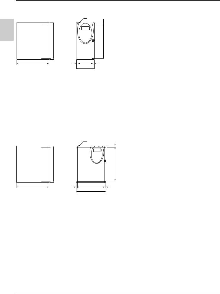
Mounting
Dimensions and weights
A
|
|
|
|
|
|
|
|
|
|
ATV31 |
|
a |
b |
c (1) |
G |
hr |
H |
Ø |
For |
Weight |
||
|
|
|
|
mm |
mm |
mm |
mm |
mm |
mm |
mm |
screw |
kg |
|
|
|
|
|
|
|
|
|
|
|
|
|
H018M3X, H037M3X |
Size 1 |
72 |
145 |
120 |
60±1 |
5 |
121.5±1 |
2 x 5 |
M4 |
0.9 |
||
|
|
|
|
|
|
|
|
|
|
|
|
|
H055M3X, H075M3X |
Size 2 |
72 |
145 |
130 |
60±1 |
5 |
121.5±1 |
2 x 5 |
M4 |
0.9 |
||
|
|
|
|
|
|
|
|
|
|
|
|
|
H018M2, H037M2 |
Size 3 |
72 |
145 |
130 |
60±1 |
5 |
121.5±1 |
2 x 5 |
M4 |
1.05 |
||
|
|
|
|
|
|
|
|
|
|
|
|
|
H055M2, H075M2 |
Size 4 |
72 |
145 |
140 |
60±1 |
5 |
121.5±1 |
2 x 5 |
M4 |
1.05 |
||
|
|
|
|
|
|
|
|
|
|
|
|
|
HU11M3X, HU15M3X |
Size 5 |
105 |
143 |
130 |
93±1 |
5 |
121.5±1 |
2 x 5 |
M4 |
1.25 |
||
|
|
|
|
|
|
|
|
|
|
|
|
|
HU11M2, HU15M2, |
Size 6 |
105 |
143 |
150 |
93±1 |
5 |
121.5±1 |
2 x 5 |
M4 |
1.35 |
||
HU22M3X, |
|
|
|
|
|
|
|
|
|
|
||
H037N4, H055N4, H075N4, |
|
|
|
|
|
|
|
|
|
|
||
HU11N4,HU15N4, |
|
|
|
|
|
|
|
|
|
|
||
H075S6X, HU15S6X |
|
|
|
|
|
|
|
|
|
|
||
|
|
|
|
|
|
|
|
|
|
|
|
|
|
|
|
|
|
|
|
|
|
|
|
|
|
|
|
|
|
|
|
|
|
|
|
|
|
|
|
|
|
|
|
|
|
|
|
|
|
|
|
|
|
|
|
|
|
|
|
|
|
ATV31 |
|
a |
b |
c (1) |
G |
hr |
H |
Ø |
For |
Weight |
|
|
mm |
mm |
mm |
mm |
mm |
mm |
mm |
screw |
kg |
|
|
|
|
|
|
|
|
|
|
|
HU22M2, HU30M3X, HU40M3X, |
Size 7 |
140 |
184 |
150 |
126±1 |
6.5 |
157±1 |
4 x 5 |
M4 |
2.35 |
HU22N4, HU30N4, HU40N4, |
|
|
|
|
|
|
|
|
|
|
HU22S6X, HU40S6X |
|
|
|
|
|
|
|
|
|
|
|
|
|
|
|
|
|
|
|
|
|
HU55M3X, HU75M3X, |
Size 8 |
180 |
232 |
170 |
160±1 |
5 |
210±1 |
4 x 5 |
M4 |
4.70 |
HU55N4, HU75N4, |
|
|
|
|
|
|
|
|
|
|
HU55S6X, HU75S6X |
|
|
|
|
|
|
|
|
|
|
|
|
|
|
|
|
|
|
|
|
|
HD11M3X, HD15M3X, |
Size 9 |
245 |
330 |
190 |
225±1 |
7 |
295±1 |
4 x 6 |
M5 |
9.0 |
HD11N4, HD15N4, |
|
|
|
|
|
|
|
|
|
|
HD11S6X, HD15S6X |
|
|
|
|
|
|
|
|
|
|
|
|
|
|
|
|
|
|
|
|
|
(1)For drives in the A range, add 8 mm for the protruding potentiometer button.
4
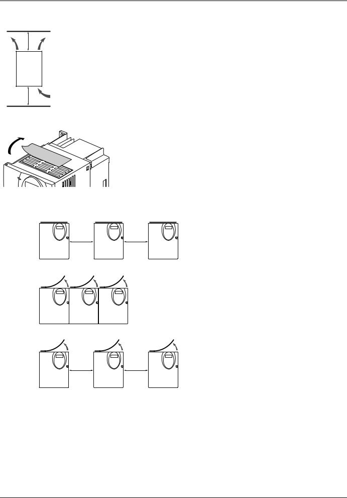
Mounting
Mounting and temperature conditions
≥ 50 mm
 ≥ 50 mm
Install the unit vertically, at ± 10°. |
|
|
|
||
Do not place it close to heating elements. |
|
|
Leave sufficient free space to ensure that the air required for cooling purposes can circulate from the bottom to |
A |
|
the top of the unit. |
||
|
||
Free space in front of unit: 10 mm minimum. |
|
|
When IP20 protection is adequate, we recommend that the protective cover on the top of the drive be removed, |
|
|
|
||
as shown below. |
|
Removing the protective cover
Example ATV31HU11M3X
3 types of mounting are possible:
Type A Free space u 50 mm on each side, with protective cover fitted mounting:
u 50 mm |
u 50 mm |
Type B Drives mounted side-by-side, protective cover removed (the degree of protection becomes IP20) mounting:
Type C Free space u 50 mm on each side, protective cover removed (the degree of protection becomes IP20) mounting:
u 50 mm |
u 50 mm |
5
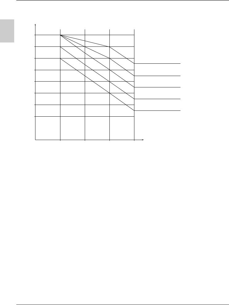
Mounting
Derating curves for the drive current In as a function of the temperature, switching frequency and type of mounting.
I/In
A |
In = 100 % |
|
|
|
|
|
- 5 % |
|
|
|
90 % |
- 10 % |
- 10 % |
|
|
|
|
|
|
|
|
- 15 % |
- 20 % |
|
|
80 % |
|
40°C mounting types A, B and C |
|
|
|
|
||
|
|
- 25 % |
|
|
|
|
- 30 % |
- 25 % |
|
|
70 % |
|
|
|
|
|
|
50°C mounting type C |
|
|
|
- 35 % |
|
|
|
|
|
- 35 % |
|
|
60 % |
|
- 40 % |
|
|
|
|
||
|
|
|
50°C mounting types A and B |
|
|
|
|
|
|
|
|
|
- 50 % |
- 45 % |
|
50 % |
|
|
|
|
|
|
60°C mounting type C |
|
|
|
|
|
|
|
|
|
|
- 55 % |
|
40 % |
|
|
60°C mounting types A and B |
|
|
|
|
|
|
|
|
|
- 65 % |
|
30 % |
|
|
|
|
|
|
|
Switching frequency |
|
4 kHz |
8 kHz |
12 kHz |
16 kHz |
For intermediate temperatures (e.g. 55°C), interpolate between 2 curves.
If you are installing the drives in enclosures, make provision for a flow of air at least equal to the value given in the table below for each drive.
ATV31 |
Flow rate in m3/hour |
H018M2, H037M2, H055M2, |
18 |
H018M3X, H037M3X, H055M3X, |
|
H037N4, H055N4, H075N4, HU11N4 |
|
H075S6X, HU15S6X |
|
|
|
H075M2, HU11M2, HU15M2 |
33 |
H075M3X, HU11M3X, HU15M3X |
|
HU15N4, HU22N4 |
|
HU22S6X, HU40S6X |
|
|
|
HU22M2, |
93 |
HU22M3X, HU30M3X, HU40M3X |
|
HU30N4, HU40N4 |
|
HU55S6X, HU75S6X |
|
|
|
HU55M3X |
102 |
HU55N4, HU75N4 |
|
HD11S6X |
|
|
|
HU75M3X, HD11M3X, |
168 |
HD11N4, HD15N4 |
|
HD15S6X |
|
|
|
HD15M3X |
216 |
|
|
6
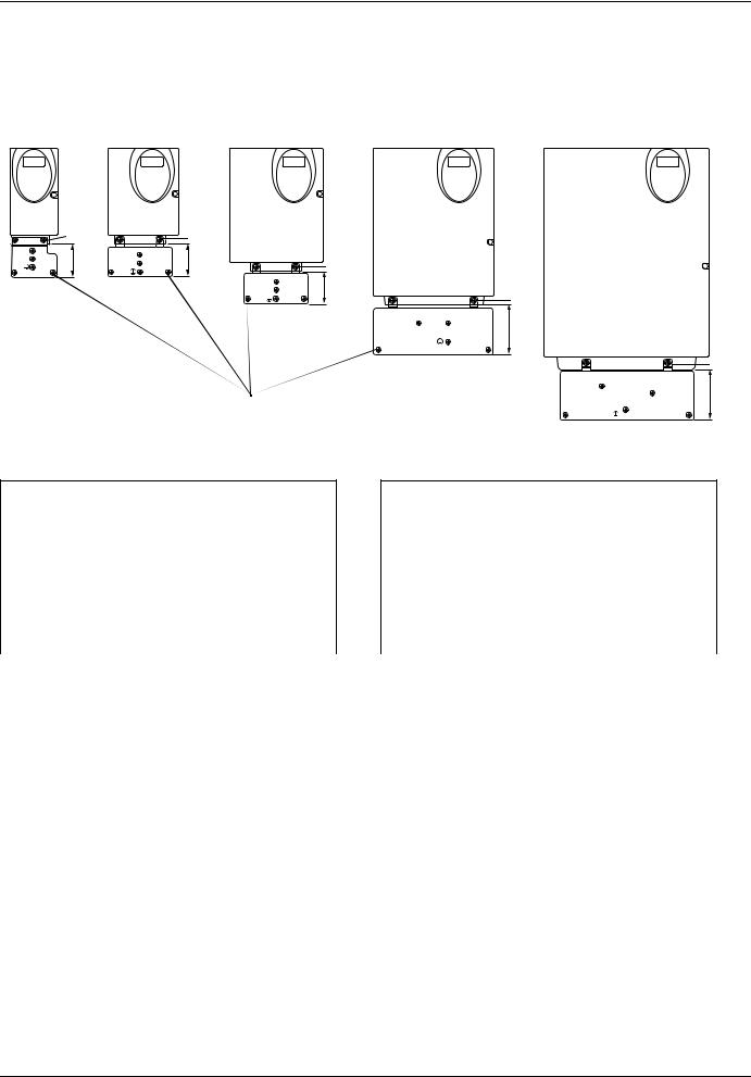
Mounting
Electromagnetic compatibility
EMC mounting plate: Supplied with the drive |
|
|
|
||
|
|
|
|||
Fix the EMC equipotentiality mounting plate to the holes in the ATV 31 heatsink using the 2 screws supplied, as shown in the drawings |
A |
||||
below. |
|
|
|
|
|
|
|
|
|
|
|
Size 1 - 4 |
Size 5 -6 |
Size 7 |
Size 8 |
Size 9 |
|
|
|
|
|
|
|
2 |
|
2 |
|
|
|
50 |
49 |
2 |
|
|
48 |
Screws supplied:
4 x M4 screws for fixing the EMC clamps (clamps not supplied) 1 x M5 screw for ground
ATV31
H018M3X, H037M3X |
Size 1 |
|
|
H055M3X, H075M3X |
Size 2 |
|
|
H018M2, H037M2 |
Size 3 |
|
|
H055M2, H075M2 |
Size 4 |
|
|
HU11M3X, HU15M3X |
Size 5 |
|
|
HU11M2, HU15M2, HU22M3X, |
Size 6 |
H037N4, H055N4, H075N4, HU11N4, HU15N4, |
|
H075S6X, HU15S6X |
|
|
|
2
75
2
75
ATV31
HU22M2, HU30M3X, HU40M3X, |
Size 7 |
HU22N4, HU30N4, HU40N4, |
|
HU22S6X, HU40S6X |
|
|
|
HU55M3X, HU75M3X, |
Size 8 |
HU55N4, HU75N4, |
|
HU55S6X, HU75S6X |
|
|
|
HD11M3X, HD15M3X, |
Size 9 |
HD11N4, HD15N4, |
|
HD11S6X, HD15S6X |
|
|
|
7
Wiring
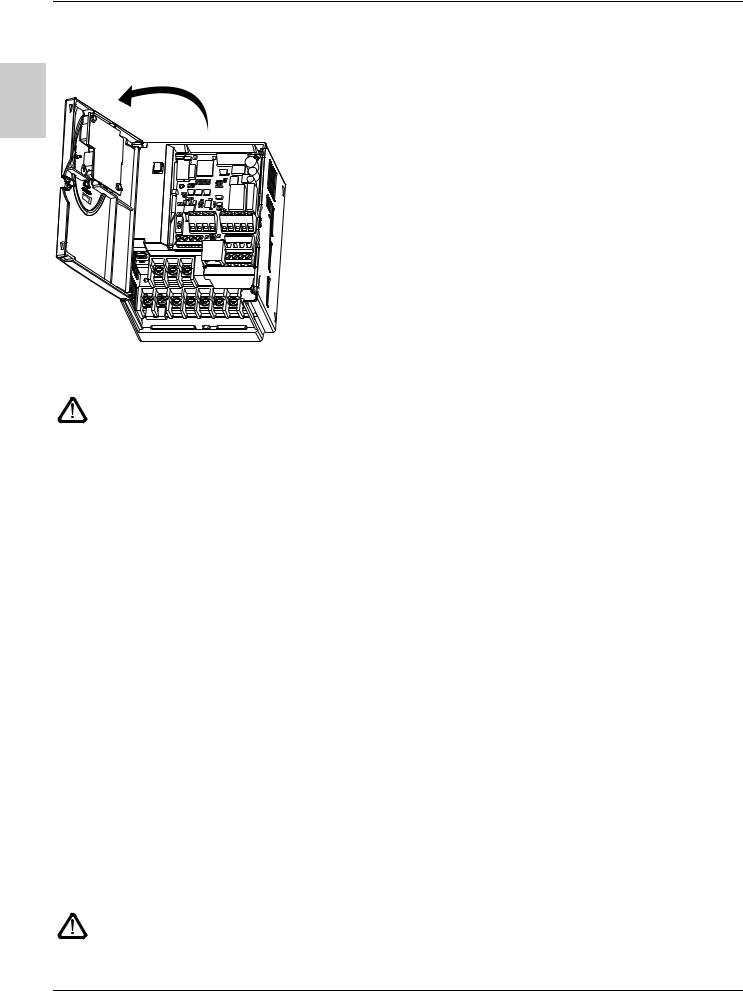
Access to terminals
To access the terminals, open the cover as shown in the example below.
A
Example ATV31HU11M2
Power terminals
Connect the power terminals before connecting the control terminals.
Power terminal characteristics
ATV 31 |
Maximum connection capacity |
Tightening torque |
||
|
AWG |
|
mm2 |
in Nm |
|
|
|||
H018M2, H037M2, H055M2, H075M2, |
AWG 14 |
|
2.5 |
0.8 |
H018M3X, H037M3X, H055M3X, H075M3X, HU11M3X, HU15M3X |
|
|
|
|
|
|
|
|
|
HU11M2, HU15M2, HU22M2, |
AWG 10 |
|
6 |
1.2 |
HU22M3X, HU30M3X, HU40M3X, |
|
|
|
|
H037N4, H055N4, H075N4, HU11N4,HU15N4, HU22N4, HU30N4, HU40N4 |
|
|
|
|
H075S6X, HU15S6X, HU22S6X, HU40S6X |
|
|
|
|
|
|
|
|
|
HU55M3X, HU75M3X, |
AWG 6 |
|
16 |
2.5 |
HU55N4, HU75N4, |
|
|
|
|
HU55S6X, HU75S6X |
|
|
|
|
|
|
|
|
|
HD11M3X, HD15M3X, |
AWG 3 |
|
25 |
4.5 |
HD11N4, HD15N4, |
|
|
|
|
HD11S6X, HD15S6X |
|
|
|
|
|
|
|
|
|
Power terminal functions
Terminal |
Function |
For ATV 31 |
|
|
|
t |
Ground terminal |
All ratings |
|
|
|
R/L1 |
Power supply |
ATV31ppppM2 |
S/L2 |
|
|
|
|
|
R/L1 |
|
ATV31ppppM3X |
S/L2 |
|
ATV31ppppN4 |
T/L3 |
|
ATV31ppppS6X |
|
|
|
PO |
DC bus + polarity |
All ratings |
|
|
|
PA/+ |
Output to braking resistor (+ polarity) |
All ratings |
|
|
|
PB |
Output to braking resistor |
All ratings |
|
|
|
PC/- |
DC bus - polarity |
All ratings |
|
|
|
U/T1 |
Outputs to the motor |
All ratings |
V/T2 |
|
|
W/T3 |
|
|
|
|
|
Never remove the commoning link between PO and PA/+. The PO and PA/+ terminal screws must always be fully tightened as a high current flows through the commoning link.
8

Wiring
Arrangement of the power terminals
ATV 31H018M3X, H037M3X, H055M3X, H075M3X |
ATV 31H018M2, H037M2, H055M2, H075M2 |
||||||||
|
|
|
|
|
|
|
|
|
|
|
|
|
|
|
|
|
|
|
|
|
|
R/L1 |
S/L2 |
T/L3 |
|
|
|
|
|
R/L1 |
S/L2 |
|
|
|
P0 |
PA/+ |
PB |
PC/- |
U/T1 |
V/T2 |
W/T3 |
|
P0 |
PA/+ |
PB |
PC/- |
U/T1 |
V/T2 |
W/T3 |
|
|
|
|
|
|
|
|
|
|
|
|
|
|
|
ATV 31HU11M3X, HU15M3X, HU22M3X, HU30M3X, HU40M3X, |
|
H037N4, H055N4, H075N4, HU11N4, HU15N4, HU22N4, |
|
HU30N4, HU40N4, H075S6X, HU15S6X, HU22S6X, |
ATV 31HU11M2, HU15M2, HU22M2 |
HU40S6X |
R/L1 |
S/L2 |
T/L3 |
|
P0 PA/+ |
PB |
PC/- U/T1 V/T2 W/T3 |
R/L1 S/L2 |
|
|
P0 |
PA/+ PB PC/- U/T1 V/T2 W/T3 |
ATV 31HU55M3X, HU75M3X, HU55N4, HU75N4, HU55S6X, HU75S6X
R/L1 S/L2 T/L3 P0 PA/+ PB PC/- U/T1 V/T2 W/T3 
ATV 31HD11M3X, HD15M3X, HD11N4, HD15N4, HD11S6X, HD15S6X


 R/L1 S/L2 T/L3 P0 PA/+ PB PC/- U/T1 V/T2 W/T3


A
9
Wiring
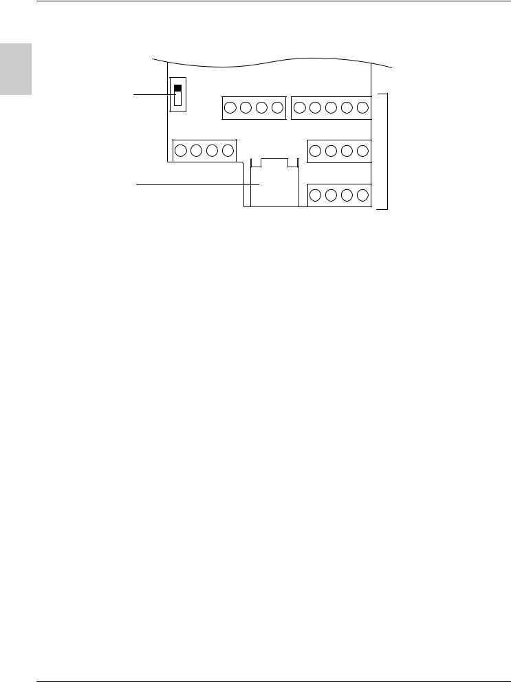
Control terminals
A |
Source |
AI3 COM AOV AOC |
R1A |
R1B |
R1C |
R2A |
R2C |
|
Logic input |
||||||||
|
|
|
|
|
|
|||
configuration |
CLI |
|
|
|
|
|
|
|
switch |
SINK |
|
|
|
|
|
|
|
|
|
|
|
|
|
|
||
COM |
AI1 10V AI2 |
|
LI4 |
LI5 |
LI6 |
CLI |
||
RJ45 |
|
RJ45 |
|
24V |
LI1 |
LI2 |
LI3 |
|
connector |
|
|
|
|
|
|
||
-Maximum connection capacity: 2.5 mm2 - AWG 14
-Max. tightening torque: 0.6 Nm
Control terminals
10

Wiring
Control terminals
Arrangement, characteristics and functions of the control terminals
Terminal |
Function |
Electrical characteristics |
A |
|
|
|
|
R1A |
Common point C/O contact (R1C) of |
• Min. switching capacity: 10 mA for 5 V c |
|
R1B |
programmable relay R1 |
• Max. switching capacity on resistive load (cos ϕ = 1 and L/R = 0 ms): |
|
R1C |
|
5 A for 250 V a and 30 V c |
|
|
|
• Max. switching capacity on inductive load (cos ϕ = 0.4 and L/R = 7 ms): |
|
R2A |
N/O contact of programmable relay R2 |
|
|
R2C |
|
1.5 A for 250 V a and 30 V c |
|
|
• Sampling time 8 ms |
|
|
|
|
|
|
|
|
• Service life: 100,000 operations at max. switching power |
|
|
|
1,000,000 operations at min. switching power |
|
|
|
|
|
|
|
|
|
COM |
Analog I/O common |
0 V |
|
|
|
|
|
AI1 |
Analog voltage input |
Analog input 0 + 10 V (max. safe voltage 30 V) |
|
|
|
• Impedance 30 kΩ |
|
|
|
• Resolution 0.01 V, 10-bit converter |
|
|
|
• Precision ± 4.3%, linearity ± 0.2%, of max. value |
|
|
|
• Sampling time 8 ms |
|
|
|
• Operation with shielded cable 100 m max. |
|
|
|
|
|
10 V |
Power supply for setpoint |
+10 V (+ 8% - 0), 10 mA max, protected against short-circuits and overloads |
|
|
potentiometer |
|
|
|
1 to 10 kΩ |
|
|
|
|
|
|
AI2 |
Analog voltage input |
Bipolar analog input 0 ± 10 V (max. safe voltage ± 30 V) |
|
|
|
The + or - polarity of the voltage on AI2 affects the direction of the setpoint and |
|
|
|
therefore the direction of operation. |
|
|
|
• Impedance 30 kΩ |
|
|
|
• Resolution 0.01 V, 10-bit + sign converter |
|
|
|
• Precision ± 4.3%, linearity ± 0.2%, of max. value |
|
|
|
• Sampling time 8 ms |
|
|
|
• Operation with shielded cable 100 m max. |
|
|
|
|
|
|
|
|
|
AI3 |
Analog current input |
Analog input X - Y mA. X and Y can be programmed from 0 to 20 mA |
|
|
|
• Impedance 250 Ω |
|
|
|
• Resolution 0.02 mA, 10-bit converter |
|
|
|
• Precision ± 4.3%, linearity ± 0.2%, of max. value |
|
|
|
• Sampling time 8 ms |
|
|
|
|
|
COM |
Analog I/O common |
0 V |
|
|
|
|
|
AOV |
Analog voltage output AOV |
Analog output 0 to 10 V, min. load impedance 470 Ω |
|
|
or |
or |
|
AOC |
Analog current output AOC |
Analog output X - Y mA. X and Y can be programmed from 0 to 20 mA, |
|
|
or |
max. load impedance 800 Ω |
|
|
Logic voltage output AOC |
• Resolution 8 bits (1) |
|
|
AOV or AOC can be assigned |
• Precision ± 1% (1) |
|
|
(either, but not both) |
• Linearity ± 0.2% (1) |
|
|
|
• Sampling time 8 ms |
|
|
|
This analog output can be configured as a 24 V logic output on AOC, min. load |
|
|
|
impedance 1.2 kΩ. |
|
|
|
(1) Characteristics of digital/analog converter. |
|
|
|
|
|
|
|
|
|
24 V |
Logic input power supply |
+ 24 V protected against short-circuits and overloads, min. 19 V, max. 30 V |
|
|
|
Max. customer current available 100 mA |
|
|
|
|
|
LI1 |
Logic inputs |
Programmable logic inputs |
|
LI2 |
|
• + 24 V power supply (max. 30 V) |
|
LI3 |
|
• Impedance 3.5 kΩ |
|
|
|
• State 0 if < 5 V, state 1 if > 11 V (voltage difference between LIand CLI) |
|
|
|
• Sampling time 4 ms |
|
|
|
|
|
|
|
|
|
LI4 |
Logic inputs |
Programmable logic inputs |
|
LI5 |
|
• + 24 V power supply (max. 30 V) |
|
LI6 |
|
• Impedance 3.5 kΩ |
|
|
|
• State 0 if < 5 V, state 1 if > 11 V (voltage difference between LIand CLI) |
|
|
|
• Sampling time 4 ms |
|
|
|
|
|
CLI |
Logic input common |
See page 12. |
|
|
|
|
|
11
Wiring
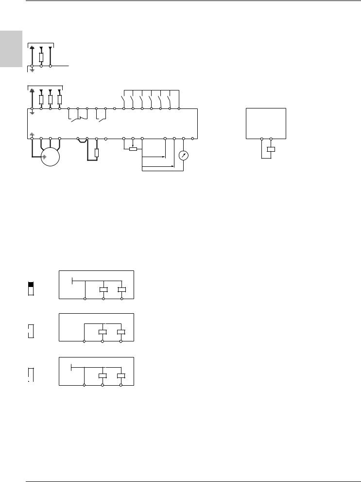
Wiring diagram for factory settings
ATV31ppppM2
A |
|
|
Single-phase supply |
|
|
|
|
|
|
|
|
|
|||
|
|
|
|
|
|
|
|
|
|
|
|
||||
|
(1) |
|
|
|
|
|
|
|
|
|
|
|
|
|
|
R / L1 |
S / L2 |
|
ATV31ppppM3X/N4/S6X |
|
|
|
|
|
|
|
|||||
|
|
|
|
|
|
|
|
|
|
||||||
|
|
|
3-phase supply |
|
|
|
|
|
|
|
|
|
|
||
|
|
(1) |
(2) |
|
|
|
|
|
|
|
|
|
|
|
|
|
|
|
|
|
|
|
|
|
|
|
|
|
|
|
|
R / L1 |
S / L2 |
T / L3 R1A |
R1C |
R1B |
R2A |
R2C |
CLI |
LI1 |
LI2 |
LI3 |
LI4 |
LI5 |
LI6 |
24V |
|
U / T1 |
V / T2 |
W / T3 |
P0 |
PA / + |
PB |
PC / - |
|
+10 |
AI1 |
COM |
|
AI3 |
AI2 |
AOV |
AOC |
U1 |
V1 |
W1 |
|
|
|
|
|
|
|
|
|
|
|
|
|
|
M |
|
|
|
|
|
|
Reference |
|
X - Y mA |
|
|
|
||
|
|
|
|
|
|
|
|
|
|
|
|
|
|||
|
3 a |
Braking resistor, |
|
potentiometer |
0 ± 10 V |
|
|
|
|||||||
|
|
|
|
|
|
|
|
|
|
||||||
|
|
|
|
|
|
|
|
|
|
|
|
||||
|
|
|
if used |
|
|
|
|
|
|
|
|
|
|
|
|
(1)Line choke, if used (single phase or 3-phase)
(2)Fault relay contacts, for remote indication of the drive status.
Using the analog output as a logic output
COM |
A0C |
24 V relay or
24 V PLC input or
LED
Note: Fit interference suppressors to all inductive circuits near the drive or coupled to the same circuit (relays, contactors, solenoid valves, etc).
Choice of associated components:
Please refer to the catalogue.
Logic input switch
This switch assigns the logic input common link to 0V, 24 V or "floating":
|
ATV31Hpppp |
|
0V |
SOURCE |
CLI at 0 V (factory setting) |
CLI LI1 LIx
ATV31Hpppp
CLI "floating"
 CLI
CLI
CLI LI1 LIx
ATV31Hpppp
24V
CLI at 24 V
 SINK
SINK
CLI LI1 LIx
12
Wiring
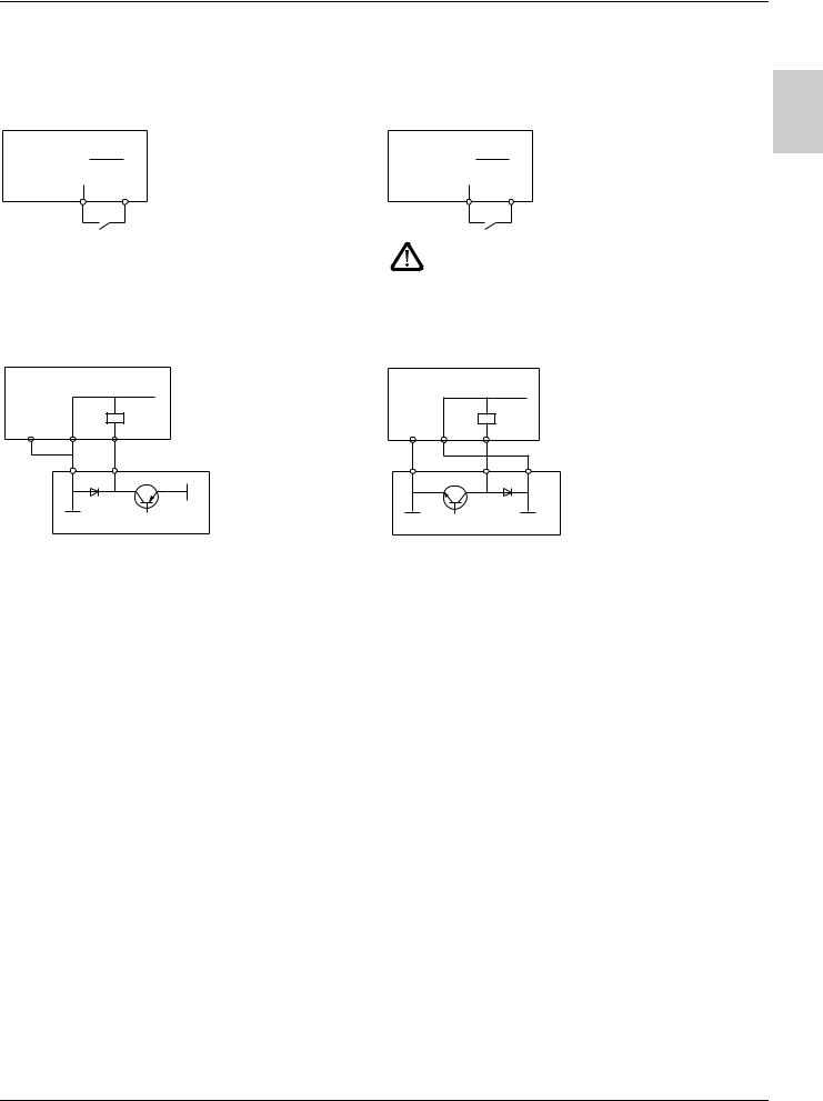
Examples of recommended circuit diagrams
Using volt-free contacts
• Switch in "Source" position |
• Switch in "SINK" position |
||||||||||
(ATV31 factory setting for types other than ATV31ppppA) |
(factory setting for ATV31ppppA) |
||||||||||
ATV31Hpppp |
ATV31Hpppp |
||||||||||
0V |
|
|
|
|
|
24V |
|
|
|
|
|
|
|
|
|
|
|
|
|
||||
|
|
|
|
|
|
|
|
|
|
|
|
|
|
|
|
|
|
|
|
|
|
|
|
LI1 |
24V |
LI1 |
COM |
A
In this instance, the common must never be connected to earth or earth ground, as this presents a risk of unintended equipment operation on the first insulation fault.
Using PLC transistor outputs
• Switch in CLI position
ATV31Hpppp
COM CLI |
LI1 |
24V
0V PLC
• Switch in CLI position
ATV31Hpppp
COM |
CLI |
LI1 |
0V |
PLC |
24V |
|
|
Wiring recommendations
Power
The drive must be earthed to conform with the regulations concerning high leakage currents (over 3.5 mA).
When upstream protection by means of a "residual current device" is required by the installation standards, a type A device should be used for single-phase drives and type B for 3-phase drives. Choose a suitable model incorporating:
•HF current filtering
•A time delay which prevents tripping caused by the load from stray capacitance on power-up. The time delay is not possible for 30 mA
devices. In this case, choose devices with immunity against accidental tripping, for example RCDs with reinforced immunity from the s.i range (Merlin Gerin brand).
If the installation includes several drives, provide one "residual current device" per drive.
Keep the power cables separate from circuits in the installation with low-level signals (detectors, PLCs, measuring apparatus, video, telephone).
If you are using cables > 50 m between the drive and the motor, add output filters (please refer to the catalogue).
Control
Keep the control circuits away from the power cables. For control and speed reference circuits, we recommend using shielded twisted cables with a pitch of between 25 and 50 mm, connecting the shielding to ground at each end.
13
Wiring
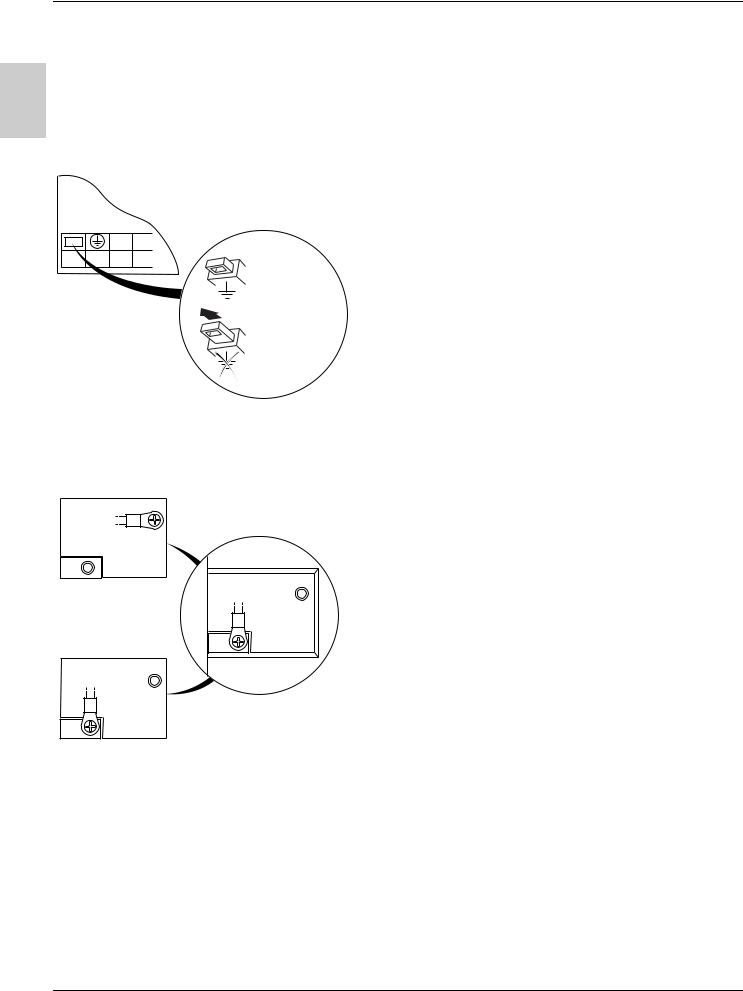
Operation on an IT system
IT system: Isolated or impedance earthed neutral.
Use a permanent insulation monitor compatible with non-linear loads (a Merlin Gerin type XM200, for example).
A ATV 31pppM2 and N4 drives feature built-in RFI filters. These filters can be isolated from ground for operation on an IT system as follows:
ATV31H018M2 to U22M2 and ATV31H037N4 to U40N4:
Pull out the jumper on the left of the ground terminal as illustrated below.
Normal (filter connected)
IT system (filter disconnected)
ATV31HU55N4 to D15N4:
Move the cable tag on the top left of the power terminals as illustrated below (example ATV31HU55N4):
IT system
(filter disconnected)
Normal
(filter connected) (factory setting)
14
Wiring
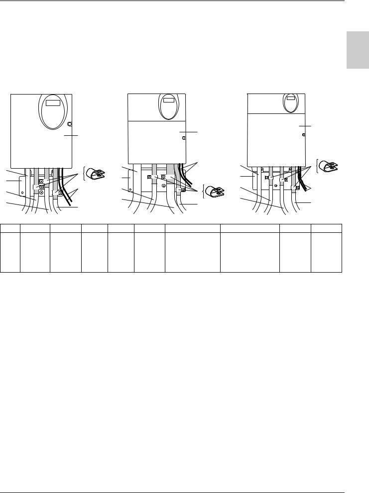
Electromagnetic compatibility
Principle
• Grounds between the drive, motor and cable shielding must have "high frequency" equipotentiality.
• Use shielded cables with shielding connected to ground throughout 360° at both ends for the motor cable 6, braking resistor (if used) 8, A and control-signalling cables 7. Metal ducting or conduit can be used for part of the shielding length provided that there is no break in continuity.
• Ensure maximum separation between the power supply cable (line supply) and the motor cable.
Installation diagram (examples)
Sizes 1 to 7 Size 8 Size 9
|
|
|
|
|
|
2 |
|
|
2 |
|
|
2 |
|
|
|
|
|
|
|
|
|
|
|
|
|
|
|
|
|
|
|
|
|
3 |
|
4 |
3 |
|
5 |
3 |
|
|
|
|
|
|
|||
|
5 |
|
|
|
|
1 |
|
|
|
|
|
|
1 |
|
|
|
|
||
1 |
|
|
|
|
|
|
|
||
|
|
|
|
|
|
8 |
|
|
|
8 |
|
4 |
|
8 |
|
5 |
|
4 |
|
|
|
|
|
|
6 |
|
|
||
6 |
|
|
|
6 |
|
7 |
|
7 |
|
|
7 |
|
|
|
|
|
|||
|
|
|
|
|
|
|
|
|
|
|
Size 1 |
Size 2 |
Size 3 |
Size 4 |
Size 5 |
Size 6 |
Size 7 |
Size 8 |
Size 9 |
ATV3 |
H018M3X, H055M3X, |
H018M2, H055M2, HU11M3X, |
HU11M2, HU15M2 |
HU22M2 |
HU55M3X, |
HD11M3X, |
|||
1 |
H037M3X |
H075M3X |
H037M2 |
H075M2 |
HU15M3X |
HU22M3X |
HU30M3X, HU40M3X |
HU75M3X |
HD15M3X |
|
|
|
|
|
|
H037N4, H055N4, |
HU22N4, HU30N4, |
HU55N4, |
HD11N4, |
|
|
|
|
|
|
H075N4, HU11N4, |
HU40N4 |
HU75N4 |
HD15N4 |
|
|
|
|
|
|
HU15N4 |
HU22S6X, HU40S6X |
HU55S6X, |
HD11S6X, |
|
|
|
|
|
|
H075S6X, HU15S6X |
|
HU75S6X |
HD15S6X |
1Sheet steel grounded plate supplied with the drive, to be fitted as indicated on the diagram.
2ATV 31
3Non-shielded power supply wires or cable
4Non-shielded wires for relay contacts
5Fix and ground the shielding of cables 6, 7 and 8 as close as possible to the drive:
-Strip the shielding.
-Use stainless steel cable clamps of an appropriate size on the parts from which the shielding has been stripped, to attach them to the plate 1.
The shielding must be clamped tightly enough to the metal plate to ensure correct contact.
6Shielded cable for motor connection with shielding connected to ground at both ends.
The shielding must be continuous and intermediate terminals must be in EMC shielded metal boxes.
For 0.18 to 1.5 kW drives, if the switching frequency is higher than 12 kHz, use cables with low linear capacitance: max. 130 pF (picoFarads) per metre.
7Shielded cable for connecting the control/signalling wiring.
For applications requiring several conductors, use cables with a small cross-section (0.5 mm2).
The shielding must be connected to ground at both ends. The shielding must be continuous and intermediate terminals must be in EMC shielded metal boxes.
8Shielded cable for connecting braking resistor (if fitted).
The shielding must be continuous and intermediate terminals must be in EMC shielded metal boxes.
Note:
•If using an additional input filter, it should be mounted under the drive and connected directly to the line supply via an unshielded cable. Link 3 on the drive is then via the filter output cable.
•The HF equipotential ground connection between the drive, motor and cable shielding does not remove the need to connect the PE protective conductors (green-yellow) to the appropriate terminals on each unit.
15

A
16

Contents
Warnings ___________________________________________________________________________________________________________________ |
2 |
|
Steps for setting up the starter _______________________________________________________________________________________________ |
3 |
|
Factory configuration________________________________________________________________________________________________________ |
4 |
|
Software enhancements _____________________________________________________________________________________________________ |
5 |
|
Basic functions______________________________________________________________________________________________________________ |
6 |
|
Setup - Preliminary recommendations_________________________________________________________________________________________ |
8 |
|
Functions of the display and the keys _________________________________________________________________________________________ |
9 |
|
Remote terminal option_____________________________________________________________________________________________________ 11 |
|
|
Programming ______________________________________________________________________________________________________________ 12 |
|
|
Function compatibility ______________________________________________________________________________________________________ 14 |
|
|
List of functions which can be assigned to inputs/outputs______________________________________________________________________ 16 |
B |
|
List of functions which can be assigned to the CANopen and Modbus control word bits___________________________________________ 18 |
||
Settings menu SEt_________________________________________________________________________________________________________ 19 |
||
Motor control menu drC-____________________________________________________________________________________________________ 23 I/O menu I-O- ______________________________________________________________________________________________________________ 27 Control menu CtL_________________________________________________________________________________________________________ 31 Application functions menu FUn____________________________________________________________________________________________ 42 Fault menu FLt____________________________________________________________________________________________________________ 66 Communication menu COM________________________________________________________________________________________________ 69 Display menu SUP_________________________________________________________________________________________________________ 70 Maintenance _______________________________________________________________________________________________________________ 73 Faults - Causes - Remedies__________________________________________________________________________________________________ 74 Configuration/Settings table ________________________________________________________________________________________________ 76 Index of parameter codes ___________________________________________________________________________________________________ 80 Index of functions __________________________________________________________________________________________________________ 81
NOTE: Please also refer to the "Installation Guide".
1

Warnings
B
When the drive is powered up, the power components and some of the control components are connected to the line supply. It is extremely dangerous to touch them. The drive cover must be kept closed.
In general, the drive power supply must be disconnected before any operation on either the electrical or mechanical parts of the installation or machine.
After the ATV has been switched off and the display has disappeared completely, wait for 10 minutes before working on the equipment. This is the time required for the capacitors to discharge.
The motor can be stopped during operation by inhibiting start commands or the speed reference while the drive remains powered up. If personnel safety requires prevention of sudden restarts, this electronic locking system is not sufficient: fit a cut-off on the power circuit.
The drive is fitted with safety devices which, in the event of a fault, can shut down the drive and consequently the motor. The motor itself may be stopped by a mechanical blockage. Finally, voltage variations, especially line supply failures, can also cause shutdowns.
If the cause of the shutdown disappears, there is a risk of restarting which may endanger certain machines or installations, especially those which must conform to safety regulations.
In this case the user must take precautions against the possibility of restarts, in particular by using a low speed detector to cut off power to the drive if the motor performs an unprogrammed shutdown.
The drive must be installed and set up in accordance with both international and national standards. Bringing the device into conformity is the responsibility of the systems integrator who must observe the EMC directive among others within the European Union.
The specifications contained in this document must be applied in order to comply with the essential requirements of the EMC directive.
The ATV 31 must be considered as a component: it is neither a machine nor a device ready for use in accordance with European directives (machinery directive and electromagnetic compatibility directive). It is the responsibility of the end user to ensure that the machine meets these standards.
The drive must not be used as a safety device for machines posing a potential risk of material damage or personal injury (lifting equipment, for example). In such applications, overspeed checks and checks to ensure that the trajectory remains under constant control must be made by separate devices which are independent of the drive.
The products and equipment described in this document may be changed or modified at any time, either from a technical point of view or in the way they are operated. Their description can in no way be considered contractual.
2
Steps for setting up the starter
1 - Delivery of the drive
•Check that the drive reference printed on the label is the same as that on the delivery note corresponding to the purchase order.
•Remove the ATV 31 from its packaging and check that it has not been damaged in transit.
2 - Check that the line voltage is compatible with the supply voltage range of the drive
(see the ATV 31Installation Manual).
- The drive may be damaged if the line voltage is not compatible.
3 - Fit the drive
4 - Connect the following to the drive:
•The line supply, ensuring that it is:
-compatible with the voltage range of the drive
-switched off
•The motor, ensuring that its coupling corresponds to the line voltage
•The control via the logic inputs
•The speed reference via the logic or analog inputs
B
5 - Switch on the drive, but do not give a run command 6 - Configure the following:
The nominal frequency (bFr) of the motor, if it is different from 50 Hz.
7 - Configure the following in the drCmenu:
The motor parameters, only if the factory configuration of the drive is not suitable.
8 - Configure the following in the I-O-, CtLand FUnmenus:
The application functions (only if the factory configuration of the drive is not suitable), for example the control mode: 3-wire, or 2-wire transition detection, or 2-wire level detection, or 2-wire level detection with forward direction priority, or local control for ATV31pppA.
The user must ensure that the programmed functions are compatible with the wiring diagram used.
9 - Set the following in the SEtmenu:
-The ACC (Acceleration) and dEC (Deceleration) parameters
-The LSP (Low speed when the reference is zero) and HSP (High speed when the reference is maximum) parameters
-The ItH parameter (Motor thermal protection)
10 - Start the drive
Practical recommendations
•Preparations can be made for programming the drive by filling in the configuration and settings tables (see page 76), in particular when the factory configuration has to be changed.
•It is always possible to return to the factory settings using the FCS parameter in the drC-, I-O-, CtLand FUnmenus (return to the configuration selected by the CFG parameter).
The assignment of CFG results directly in a return to the selected configuration.
•For simple applications where the factory settings are suitable, the ATV31 is configured so as to be equally robust as the ATV28 factory settings.
•To achieve optimized drive performance in terms of accuracy and response time, it is essential to:
-Enter the values given on the motor rating plate in the Motor control menu drC- (page 23).
-Perform an auto-tune operation with the motor cold and connected, using parameter tUn in the drCmenu (page 24).
(Auto-tuning measures the stator resistance of the motor in order to optimize the control algorithms).
- Adjust parameters FLG and StA in the Settings menu SEt- (page 20).
•To locate the description of a function quickly, use the index of functions on page 81.
•Before configuring a function, read the "Function compatibility" section on pages 14 and 15.
3

Factory configuration
Factory settings
The ATV 31 is factory-set for the most common operating conditions:
•Display: Drive ready (rdY) with motor stopped, and motor frequency with motor running
•Motor frequency (bFr): 50 Hz
•Constant torque application with sensorless flux vector control (UFt = n)
•Normal stop mode on deceleration ramp (Stt = rMP).
•Stop mode in the event of a fault: Freewheel
•Linear ramps (ACC, dEC): 3 seconds
•Low speed (LSP): 0 Hz
•High speed (HSP): 50 Hz
•Motor thermal current (ItH) = nominal motor current (value depending on drive rating)
B |
• Standstill injection braking current (SdC) = 0.7 x nominal drive current, for 0.5 seconds |
||
• |
Automatic adaptation of the deceleration ramp in the event of overvoltage on braking |
||
|
• No automatic restarting after a fault |
||
|
• Switching frequency 4 kHz |
||
|
• |
Logic inputs: |
|
|
|
- LI1, LI2 (2 directions of operation): 2-wire transition detection control, LI1 = forward, LI2 = reverse, inactive on ATV 31ppppppA drives |
|
|
|
|
(not assigned) |
|
|
- LI3, LI4: 4 preset speeds (speed 1 = speed reference or LSP, speed 2 = 10 Hz, speed 3 = 15 Hz, speed 4 = 20 Hz). |
|
|
|
- LI5 - LI6: Inactive (not assigned) |
|
|
• |
Analog inputs: |
|
|
|
- |
AI1: Speed reference 0-10 V, inactive on ATV 31ppppppA (not assigned) |
|
|
- |
AI2: Summed speed reference input 0±10 V |
|
|
- AI3: 4-20 mA inactive (not assigned) |
|
|
• Relay R1: The contact opens in the event of a fault (or drive off) |
||
|
• Relay R2: Inactive (not assigned) |
||
|
• Analog output AOC: 0-20 mA inactive (not assigned) |
||
ATV 31ppppppA range
When they leave the factory, ATV 31ppppppA drives are supplied with local control activated: the RUN, STOP buttons and the drive potentiometer are active. Logic inputs LI1 and LI2 and analog input AI1 are inactive (not assigned).
If the above values are compatible with the application, the drive can be used without changing the settings.
4

Software enhancements
Since it was first marketed, the ATV 31 has been equipped with additional functions. Software version V1.2 has now been updated to V1.7. This documentation relates to version V1.7.
The software version appears on the rating plate attached to the side of the drive.
Enhancements to version V1.7 compared with V1.2
New parameters
Motor control menu
• /23: Choice of source configuration for the factory settings function (see page 26). This parameter is also accessible in the I-O-, CtL-, and FUnmenus (pages 29 , 41 and 65).
Application functions menu FUn-
• 5DH: Ramp increment (see page 43)
Fault menu FLt-
• 71I: Configuration of external fault detection (see page 67).
B
New possible assignments for relays R1 and R2
• Relays R1 and R2 can now be assigned to LI1..LI6. It then returns the value of the selected logic input (see page 28).
5
Basic functions
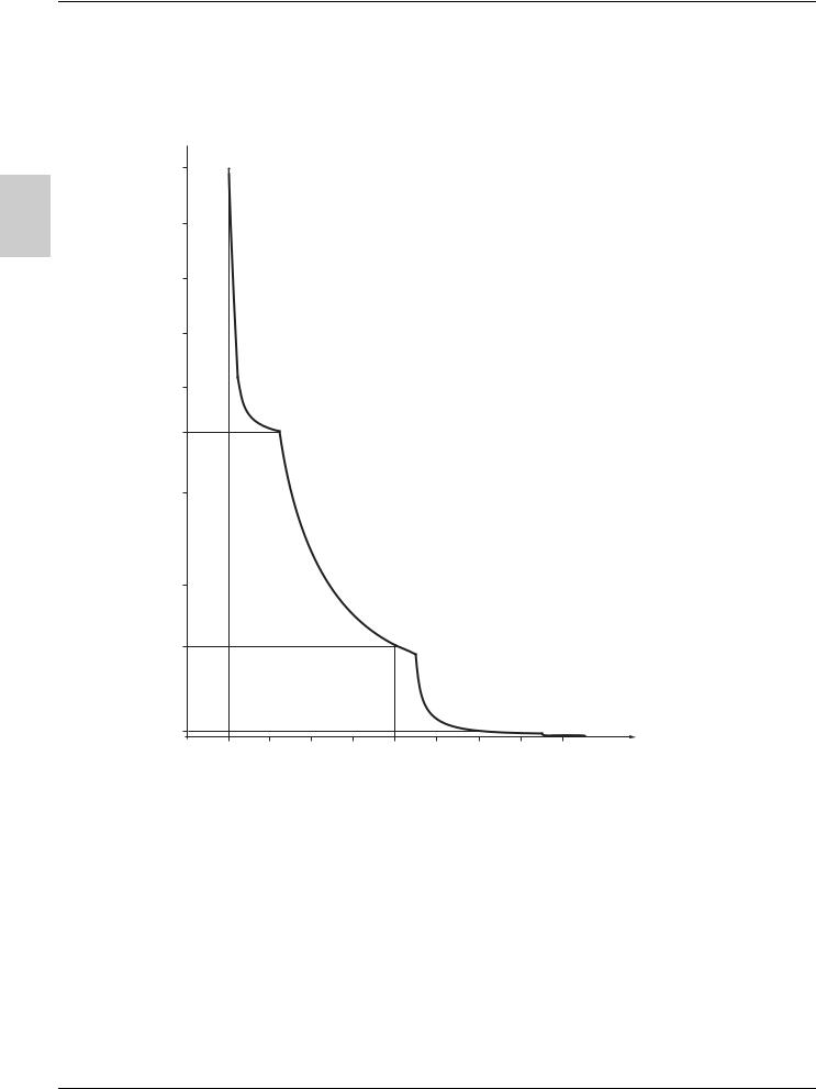
Drive thermal protection
Functions:
Thermal protection by PTC probe fitted on the heatsink or integrated in the power module.
Indirect protection of the drive against overloads by tripping in the event of an overcurrent. Typical tripping points:
-Motor current = 185% of nominal drive current: 2 seconds
-Motor current = 150% of nominal drive current: 60 seconds
Time  (seconds)
B

|
|
|
|
|
|
|
|
|
|
|
|
|
|
|
|
|
|
|
|
|
Motor current/Drive In |
|
|
|
|
|
|
|
|
|
|
Drive ventilation
The fan starts up when the drive is powered up then shuts down after 10 seconds if a run command has not been received.
The fan is powered automatically when the drive is unlocked (operating direction + reference). It is powered down a few seconds after the drive is locked (motor speed < 0.2 Hz and injection braking completed).
6
Basic functions
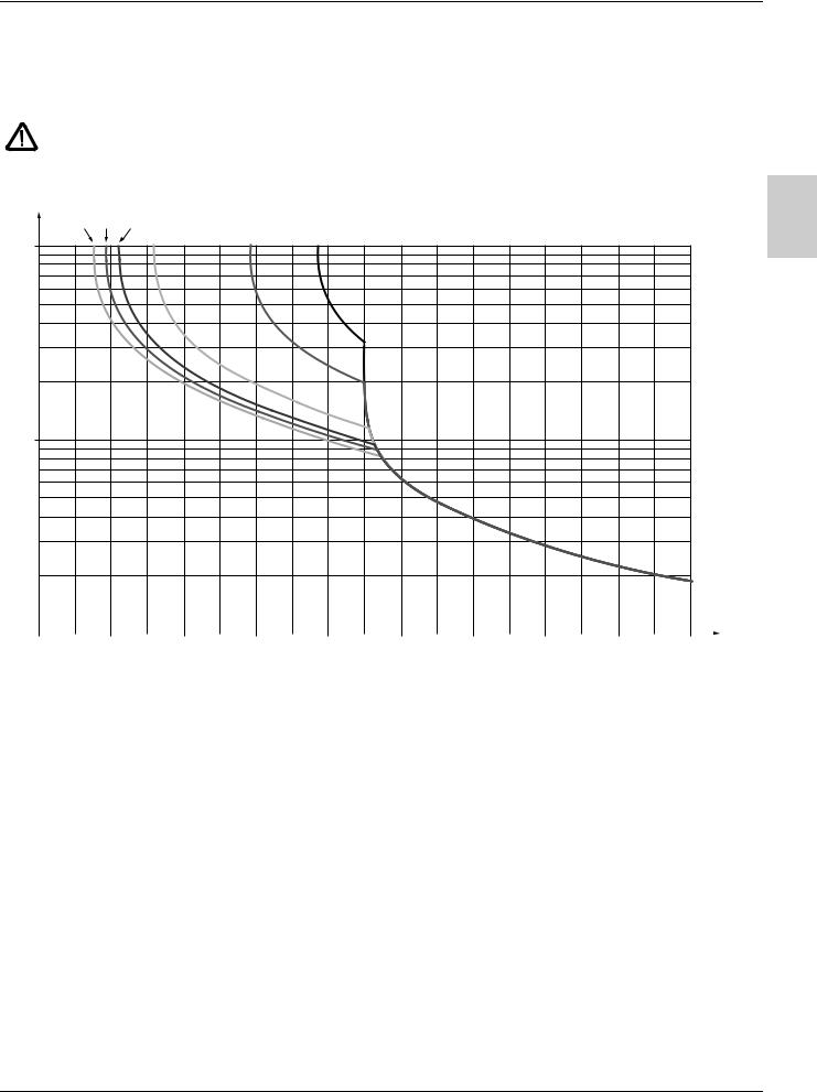
Motor thermal protection
Function:
Thermal protection by calculating the I2t.
The protection takes account of self-cooled motors.
Caution: The memory of the motor thermal state returns to zero when the drive is disconnected.
Trip time t in seconds
1 Hz 3 Hz 5 Hz |
|
|
10 Hz |
20 Hz |
50 Hz |
10 000
1 000
B
100 |
|
|
|
|
|
|
|
|
|
|
0.7 |
0.8 |
0.9 |
1 |
1.1 |
1.2 |
1.3 |
1.4 |
1.5 |
1.6 |
Motor current/ItH
7

Setup - Preliminary recommendations
Prior to switching on and configuring the drive
- Check that the line voltage is compatible with the supply voltage range of the drive (see pages 3 and 4 of the ATV 31 Installation Manual). The drive may be damaged if the line voltage is not compatible.
- Ensure the logic inputs are switched off (state 0) to prevent accidental starting. Otherwise, an input assigned to the run command may cause the motor to start immediately on exiting the configuration menus.
With power switching via line contactor
- Avoid operating the contactor frequently (premature ageing of the filter capacitors). Use inputs LI1 to LI6 to control the drive. - These instructions are vital for cycles < 60 s, otherwise the load resistor may be damaged.
B User adjustment and extension of functions
If necessary, the display and buttons can be used to modify the settings and to extend the functions described in the following pages. It is very easy to return to the factory settings using the FCS parameter in the drC-, I-O-, CtLand FUnmenus (set InI to activate the function, see page 26, 30, 41 or 65).
There are three types of parameter:
-Display: Values displayed by the drive
-Setting: Can be changed during operation or when stopped
-Configuration: Can only be modified when stopped and no braking is taking place. Can be displayed during operation.
- Check that changes to the current operating settings do not present any danger. Changes should preferably be made with the drive stopped.
Start up
Important: In factory settings mode on power-up, or in a manual fault reset or after a stop command, the motor can only be powered once the "forward", "reverse" and "DC injection stop" commands have been reset. If they have not been reset, the drive will display "nSt" but will not start. If the automatic restart function is configured (parameter Atr in the FLtmenu, see page 66), these commands are taken into account without a reset being necessary.
Test on a low power motor or without a motor
•In factory settings mode, "motor phase loss" detection is active (OPL = YES). To check the drive in a test or maintenance environment without having to switch to a motor with the same rating as the drive (particularly useful in the case of high power drives), deactivate "motor phase loss" detection (OPL = NO).
•Configure the voltage/frequency ratio: UFt = L (drCmenu on page 24)
• Motor thermal protection will not be provided by the drive if the motor current is less than 0.2 times the nominal drive current.
Using motors in parallel
• Configure the voltage/frequency ratio: UFt = L (drCmenu on page 24)
• Motor thermal protection is no longer provided by the drive. Provide an alternative means of thermal protection on every motor.
8
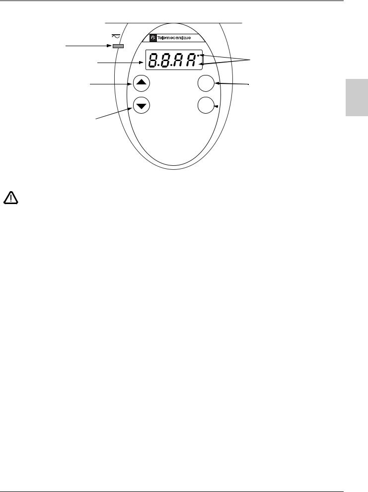
Functions of the display and the keys
• Red LED
"DC bus ON"
• Four 7-segment displays
•Returns to the previous menu or parameter, or increases the displayed value
ATV 31
 RUN
RUN
CAN |
• 2 CANopen status LEDs |


 ERR
ERR
ESC |
• Exits a menu or parameter, or |
|
|
clears the displayed value to |
B |
|
return to the previous stored |
|
ENT |
value |
|
|
|
• Goes to the next menu or parameter, or decreases the displayed value
•Pressing or
or  does not store the selection.
•Press and hold down (>2 s) or
or to scroll through the data quickly. To save and store the selection: ENT
The display flashes when a value is stored.
Normal display, with no fault present and no starting:
 • Enters a menu or a parameter, or saves the displayed parameter or value
-43.0: Display of the parameter selected in the SUPmenu (default selection: motor frequency). In current limit mode, the display flashes.
-init: Initialization sequence
-rdY: Drive ready
-dcb: DC injection braking in progress
-nSt: Freewheel stop
-FSt: Fast stop
-tUn: Auto-tuning in progress
The display flashes to indicate the presence of a fault.
9
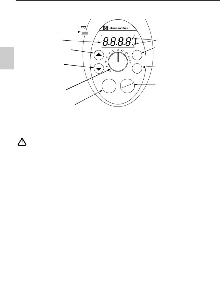
Functions of the display and the keys
ATV31ppppppA:
• Red LED |
ATV 31 |
"DC bus ON" |
|
• Four 7-segment displays |
RUN |
|
|
CAN |
||
|
|
||
|
|
ERR |
|
|
• Returns to the previous menu or |
|
|
B |
parameter, or increases the |
ESC |
|
displayed value |
|||
|
|||
|
|
||
|
• Goes to the next menu or |
|
|
|
parameter, or decreases the |
ENT |
|
|
displayed value |
|
|
RUN |
STOP |
|
• Reference potentiometer, |
RESET |
||
|
|||
active if the Fr1 parameter in the |
|
|
|
CtLmenu is configured as AIP |
|
|
• RUN button: Controls motor switch-on in forward mode, if parameter tCC in the I-O- menu is configured as LOC
•Pressing or
or  does not store the selection.
•Press and hold down (>2 s) or
or to scroll through the data quickly.
To save and store the selection: ENT
The display flashes when a value is stored.
Normal display, with no fault present and no starting:
 • 2 CANopen status LEDs
•Exits a menu or a parameter,
or clears the displayed value to return to the previous stored value
•Enters a menu or a parameter, or saves the displayed parameter or value
STOP/RESET button
•Used to reset faults
•Can be used to control motor stopping
-If tCC (I-O- menu) is not configured as LOC, it is a freewheel stop.
-If tCC (I-O- menu) is configured as LOC, stopping is on a ramp, but if injection braking is in progress, a freewheel stop takes place.
-43.0: Display of the parameter selected in the SUPmenu (default selection: output frequency applied to the motor). In current limit mode, the display flashes.
-init: Initialization sequence
-rdY: Drive ready
-dcb: DC injection braking in progress
-nSt: Freewheel stop
-FSt: Fast stop
-tUn: Auto-tuning in progress
The display flashes to indicate the presence of a fault.
10
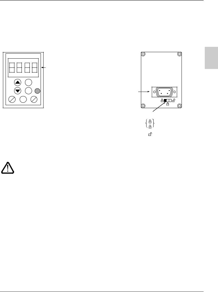
Remote terminal option
This module is a local control unit which can be mounted on the door of the wall-mounted or floor-standing enclosure. It has a cable with connectors, which is connected to the drive serial link (see the manual supplied with the terminal). It has the same display and the same programming buttons as the ATV 31 with the addition of a switch to lock access to the menus and three buttons for controlling the drive:
•FWD/REV: reversal of the direction of rotation
•RUN: motor run command
•STOP/RESET: Motor stop command or fault reset
Pressing the button a first time stops the motor, and if DC injection standstill braking is configured, pressing it a second time stops this braking.
View of the front panel:
|
|
4-character |
|
|
display unit |
|
|
ESC |
|
|
ENT |
FWD |
RUN |
STOP |
REV |
RESET |
View of the rear panel:
Connector
B
Access locking switch:
• positions: |
settings and display accessible |
|
(SEtand SUPmenus) |
• position: |
all menus can be accessed |
Note: Customer password protection has priority on the switch.
• The access locking switch on the remote terminal also prevents the drive settings being accessed via the keypad.
• When the remote terminal is disconnected, if the drive has been locked, the keypad will remain locked.
• In order for the remote terminal to be active, the tbr parameter in the COMmenu must remain in factory settings mode: 19.2 (see page 79).
Saving and loading configurations
Up to four complete configurations for ATV 31 drives can be stored on the remote terminal. These configurations can be saved, transported and transferred from one drive to another of the same rating. 4 different operations for the same device can also be stored on the terminal. See the SCS and FCS parameters in the drC-, I-O-, CtLand FUnmenus.
11
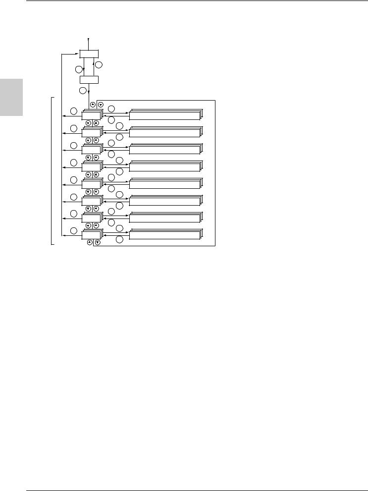
Programming
Access to menus
Power-up
Displays the drive status
|
|
|
|
|
|
|
|
Motor frequency (the factory setting is only visible |
|
|
the first time the drive is powered up) |
B |
|
|
|
|
|
|
|
|
|
|
|
|
|
Settings |
|
|
|
|
|
|
|
|
|
|
|
Motor control |
|
|
|
|
|
|
|
|
I/O |
|
|
|
|
|
|
|
|
|
|
|
|
|
|
Control |
|
Menus |
|
|
|
|
|
|
|
|
|
Functions |
|
|
|
|
|
|
|
|
|
|
|
Faults |
|
|
|
|
|
|
|
|
|
|
|
Communication |
|
|
|
|
|
|
|
|
|
|
|
Monitoring |
|
|
|
Some parameters can be accessed in a number of menus for increased user-friendliness:
-Entering settings
-Return to factory settings
-Restoring and saving the configuration
A dash appears after menu and sub-menu codes to differentiate them from parameter codes. Examples: FUnmenu, ACC parameter.
12
 Loading...