


Schneider Electric IP67 User Manual

Advantys FTB CANopen
IP67 monobloc input/output
splitter box
User guide
1606218 02 eng 3.0
1606218 02
www.telemecanique.com

2
1606218 02 08/2006

Table of Contents
Safety Information . . . . . . . . . . . . . . . . . . . . . . . . . . . . . . . . . . . . 7
About the Book . . . . . . . . . . . . . . . . . . . . . . . . . . . . . . . . . . . . . . . 9
Chapter 1 Introduction. . . . . . . . . . . . . . . . . . . . . . . . . . . . . . . . . . . . . . . . . 11
Presentation . . . . . . . . . . . . . . . . . . . . . . . . . . . . . . . . . . . . . . . . . . . . . . . . . . . . 11
Presentation of the CANopen Advantys FTB I/O Splitter Box Range . . . . . . . . . 12
Overview of the Accessories Range . . . . . . . . . . . . . . . . . . . . . . . . . . . . . . . . . . 13
Chapter 2 Installation. . . . . . . . . . . . . . . . . . . . . . . . . . . . . . . . . . . . . . . . . . 15
Presentation . . . . . . . . . . . . . . . . . . . . . . . . . . . . . . . . . . . . . . . . . . . . . . . . . . . . 15
Overview . . . . . . . . . . . . . . . . . . . . . . . . . . . . . . . . . . . . . . . . . . . . . . . . . . . . . . . 16
Installing the Unit. . . . . . . . . . . . . . . . . . . . . . . . . . . . . . . . . . . . . . . . . . . . . . . . . 17
Grounding of the Advantys FTB Splitter Box. . . . . . . . . . . . . . . . . . . . . . . . . . . . 21
EMC Compatibility. . . . . . . . . . . . . . . . . . . . . . . . . . . . . . . . . . . . . . . . . . . . . . . . 23
Chapter 3 Splitter Box Characteristics and Wiring. . . . . . . . . . . . . . . . . . 27
Presentation . . . . . . . . . . . . . . . . . . . . . . . . . . . . . . . . . . . . . . . . . . . . . . . . . . . . 27
Advantys FTB Splitter Box Environment Properties . . . . . . . . . . . . . . . . . . . . . . 28
Electrical Characteristics. . . . . . . . . . . . . . . . . . . . . . . . . . . . . . . . . . . . . . . . . . . 29
Connecting the Actuators and Sensors. . . . . . . . . . . . . . . . . . . . . . . . . . . . . . . . 30
Power Supply Connection. . . . . . . . . . . . . . . . . . . . . . . . . . . . . . . . . . . . . . . . . . 32
Chapter 4 CANopen Network Interface . . . . . . . . . . . . . . . . . . . . . . . . . . .35
Presentation . . . . . . . . . . . . . . . . . . . . . . . . . . . . . . . . . . . . . . . . . . . . . . . . . . . . 35
4.1 Wiring on the CANopen Bus . . . . . . . . . . . . . . . . . . . . . . . . . . . . . . . . . . . . . . . . 37
Presentation . . . . . . . . . . . . . . . . . . . . . . . . . . . . . . . . . . . . . . . . . . . . . . . . . . . . 37
Introduction to Wiring on the CANopen Bus . . . . . . . . . . . . . . . . . . . . . . . . . . . . 38
Topology . . . . . . . . . . . . . . . . . . . . . . . . . . . . . . . . . . . . . . . . . . . . . . . . . . . . . . . 39
Choice of system cables . . . . . . . . . . . . . . . . . . . . . . . . . . . . . . . . . . . . . . . . . . . 42
Connecting the Field Bus . . . . . . . . . . . . . . . . . . . . . . . . . . . . . . . . . . . . . . . . . . 44
Configuring the Address and Transmission Speed. . . . . . . . . . . . . . . . . . . . . . . 46
4.2 General Principles. . . . . . . . . . . . . . . . . . . . . . . . . . . . . . . . . . . . . . . . . . . . . . . . 48
Presentation . . . . . . . . . . . . . . . . . . . . . . . . . . . . . . . . . . . . . . . . . . . . . . . . . . . . 48
About CANopen . . . . . . . . . . . . . . . . . . . . . . . . . . . . . . . . . . . . . . . . . . . . . . . . . 49
The Device Profile. . . . . . . . . . . . . . . . . . . . . . . . . . . . . . . . . . . . . . . . . . . . . . . . 52
1606218 02 08/2006 3

CANopen "Boot-Up". . . . . . . . . . . . . . . . . . . . . . . . . . . . . . . . . . . . . . . . . . . . . . . 53
Process Data Object (PDO) Transmission . . . . . . . . . . . . . . . . . . . . . . . . . . . . . 56
Inhibit Time and Event Timer. . . . . . . . . . . . . . . . . . . . . . . . . . . . . . . . . . . . . . . . 60
Access to Data by Explicit Exchanges (SDO) . . . . . . . . . . . . . . . . . . . . . . . . . . . 61
"Node-Guarding" and "Life-Guarding" Monitoring Protocols. . . . . . . . . . . . . . . . 62
The "Heartbeat" Error Monitoring Protocol . . . . . . . . . . . . . . . . . . . . . . . . . . . . . 65
4.3 Behavior of FTB CANopen Splitter boxes . . . . . . . . . . . . . . . . . . . . . . . . . . . . . . 66
Presentation. . . . . . . . . . . . . . . . . . . . . . . . . . . . . . . . . . . . . . . . . . . . . . . . . . . . . 66
Behavior at Power-up . . . . . . . . . . . . . . . . . . . . . . . . . . . . . . . . . . . . . . . . . . . . . 67
Behavior in the Case of Communication Error. . . . . . . . . . . . . . . . . . . . . . . . . . . 68
Saving / Restoring Parameters . . . . . . . . . . . . . . . . . . . . . . . . . . . . . . . . . . . . . . 69
List of Saved Parameters. . . . . . . . . . . . . . . . . . . . . . . . . . . . . . . . . . . . . . . . . . . 70
Chapter 5 Application-Specific Functions . . . . . . . . . . . . . . . . . . . . . . . . 71
Presentation. . . . . . . . . . . . . . . . . . . . . . . . . . . . . . . . . . . . . . . . . . . . . . . . . . . . . 71
List of Objects . . . . . . . . . . . . . . . . . . . . . . . . . . . . . . . . . . . . . . . . . . . . . . . . . . . 72
Description of the Discrete Inputs . . . . . . . . . . . . . . . . . . . . . . . . . . . . . . . . . . . . 74
Description of Discrete Outputs . . . . . . . . . . . . . . . . . . . . . . . . . . . . . . . . . . . . . . 75
Description of Configurable Discrete I/Os . . . . . . . . . . . . . . . . . . . . . . . . . . . . . . 76
List of Advantys FTB 1CN08E08SP0 Splitter Box I/O Objects . . . . . . . . . . . . . . 78
List of Advantys FTB 1CN12E04SP0 Splitter Box I/O Objects . . . . . . . . . . . . . . 81
List of Advantys FTB 1CN16EP0 and FTB 1CN16EM0 Splitter Box I/O Objects 85
List of Advantys FTB 1CN16CP0 and FTB 1CN16CM0 Splitter Box I/O Objects 87
List of Advantys FTB 1CN08E08CM0 Splitter Box I/O Objects . . . . . . . . . . . . . . 91
Chapter 6 Software Tools . . . . . . . . . . . . . . . . . . . . . . . . . . . . . . . . . . . . . . 97
Presentation. . . . . . . . . . . . . . . . . . . . . . . . . . . . . . . . . . . . . . . . . . . . . . . . . . . . . 97
6.1 Introduction to Software Tools . . . . . . . . . . . . . . . . . . . . . . . . . . . . . . . . . . . . . . . 99
Introduction . . . . . . . . . . . . . . . . . . . . . . . . . . . . . . . . . . . . . . . . . . . . . . . . . . . . . 99
6.2 Product Configuration . . . . . . . . . . . . . . . . . . . . . . . . . . . . . . . . . . . . . . . . . . . . 101
At A Glance . . . . . . . . . . . . . . . . . . . . . . . . . . . . . . . . . . . . . . . . . . . . . . . . . . . . 101
Characteristics of an EDS File. . . . . . . . . . . . . . . . . . . . . . . . . . . . . . . . . . . . . . 102
Existing EDS File for CANopen Advantys FTB Splitter Box . . . . . . . . . . . . . . . 103
Creating a New EDS and DCF Configuration File . . . . . . . . . . . . . . . . . . . . . . . 104
6.3 Network Configuration . . . . . . . . . . . . . . . . . . . . . . . . . . . . . . . . . . . . . . . . . . . . 107
Setting the Network Parameters . . . . . . . . . . . . . . . . . . . . . . . . . . . . . . . . . . . . 107
6.4 PLC Programming . . . . . . . . . . . . . . . . . . . . . . . . . . . . . . . . . . . . . . . . . . . . . . . 114
Presentation. . . . . . . . . . . . . . . . . . . . . . . . . . . . . . . . . . . . . . . . . . . . . . . . . . . . 114
Integration and Use under PL7 . . . . . . . . . . . . . . . . . . . . . . . . . . . . . . . . . . . . . 115
Examples of SDO Requests . . . . . . . . . . . . . . . . . . . . . . . . . . . . . . . . . . . . . . . 120
Chapter 7 Diagnostics. . . . . . . . . . . . . . . . . . . . . . . . . . . . . . . . . . . . . . . . 123
Presentation. . . . . . . . . . . . . . . . . . . . . . . . . . . . . . . . . . . . . . . . . . . . . . . . . . . . 123
Power Supply Diagnostics. . . . . . . . . . . . . . . . . . . . . . . . . . . . . . . . . . . . . . . . . 124
Field Bus Status Diagnostics LED . . . . . . . . . . . . . . . . . . . . . . . . . . . . . . . . . . . 125
LED Status Diagnostics for I/O . . . . . . . . . . . . . . . . . . . . . . . . . . . . . . . . . . . . . 126
4 1606218 02 08/2006

CANopen Objects Diagnostics . . . . . . . . . . . . . . . . . . . . . . . . . . . . . . . . . . . . . 127
Behavior in the Event of Short-circuit / Overload / Under-voltage. . . . . . . . . . . 130
Chapter 8 The Object Dictionary. . . . . . . . . . . . . . . . . . . . . . . . . . . . . . . .131
Presentation . . . . . . . . . . . . . . . . . . . . . . . . . . . . . . . . . . . . . . . . . . . . . . . . . . . 131
8.1 The Object Dictionary . . . . . . . . . . . . . . . . . . . . . . . . . . . . . . . . . . . . . . . . . . . . 133
The Object Dictionary. . . . . . . . . . . . . . . . . . . . . . . . . . . . . . . . . . . . . . . . . . . . 133
8.2 Objects of the Communication Profile 1000H to 1FFFH . . . . . . . . . . . . . . . . . 134
At a Glance . . . . . . . . . . . . . . . . . . . . . . . . . . . . . . . . . . . . . . . . . . . . . . . . . . . . 134
Object 1000H: Device Type . . . . . . . . . . . . . . . . . . . . . . . . . . . . . . . . . . . . . . . 135
Object 1001H: Error Register . . . . . . . . . . . . . . . . . . . . . . . . . . . . . . . . . . . . . . 136
Object 1002H: Manufacturer Status Register . . . . . . . . . . . . . . . . . . . . . . . . . . 137
Object 1003H: Pre-defined Error Field . . . . . . . . . . . . . . . . . . . . . . . . . . . . . . . 138
Object 1005H: COB-ID SYNC Message. . . . . . . . . . . . . . . . . . . . . . . . . . . . . . 140
Object 1006H: Communication Cycle Period . . . . . . . . . . . . . . . . . . . . . . . . . . 141
Object 1008H: Manufacturer Device Name. . . . . . . . . . . . . . . . . . . . . . . . . . . . 142
Object 100AH: Manufacturer Software Version (MSV). . . . . . . . . . . . . . . . . . . 143
Object 100CH: Guard Time. . . . . . . . . . . . . . . . . . . . . . . . . . . . . . . . . . . . . . . . 144
Object 100DH: Life Time Factor . . . . . . . . . . . . . . . . . . . . . . . . . . . . . . . . . . . . 145
Object 1010H: Store Parameters . . . . . . . . . . . . . . . . . . . . . . . . . . . . . . . . . . . 146
Object 1011H: Restore Default Parameters . . . . . . . . . . . . . . . . . . . . . . . . . . . 148
Object 1014H: COB-ID Emergency Message (EMCY) . . . . . . . . . . . . . . . . . . . 150
Object 1016H: Consumer Heartbeat Time . . . . . . . . . . . . . . . . . . . . . . . . . . . . 151
Object 1017H: Producer Heartbeat Time . . . . . . . . . . . . . . . . . . . . . . . . . . . . . 152
Object 1018H: Identity Object . . . . . . . . . . . . . . . . . . . . . . . . . . . . . . . . . . . . . . 153
Object 1200H: Server SDO Parameter . . . . . . . . . . . . . . . . . . . . . . . . . . . . . . . 154
Object 1400H: 1st Receive PDO Communication Parameter. . . . . . . . . . . . . . 155
Object 1405H: 2nd Receive PDO Communication Parameter . . . . . . . . . . . . . 156
Object 1600H: 1st Receive PDO Mapping Parameter . . . . . . . . . . . . . . . . . . . 157
Object 1605H: 2nd Receive PDO Mapping Parameter. . . . . . . . . . . . . . . . . . . 159
Object 1800H: 1st Transmit PDO Communication Parameter. . . . . . . . . . . . . 161
Object 1805H: 2nd Transmit PDO Communication Parameter . . . . . . . . . . . . 164
Object 1A00H: 1st Transmit PDO Mapping Parameter. . . . . . . . . . . . . . . . . . . 167
Object 1A05H: 2nd Transmit PDO Mapping Parameter . . . . . . . . . . . . . . . . . . 169
8.3 Manufacturer-specific Zone Objects 2000H to 5FFFH . . . . . . . . . . . . . . . . . . . 171
At a Glance . . . . . . . . . . . . . . . . . . . . . . . . . . . . . . . . . . . . . . . . . . . . . . . . . . . . 171
Object 2000H: Input / Diag Parameter . . . . . . . . . . . . . . . . . . . . . . . . . . . . . . . 172
Object 2001H: Input/Output Parameter. . . . . . . . . . . . . . . . . . . . . . . . . . . . . . . 173
Object 3000H: Manufacturer Specific Diagnostic . . . . . . . . . . . . . . . . . . . . . . . 174
8.4 Hardware Profile Objects 6000H to 9FFFH . . . . . . . . . . . . . . . . . . . . . . . . . . . 175
At a Glance . . . . . . . . . . . . . . . . . . . . . . . . . . . . . . . . . . . . . . . . . . . . . . . . . . . . 175
Object 6000H: Read Inputs 8 Bits. . . . . . . . . . . . . . . . . . . . . . . . . . . . . . . . . . . 176
Object 6100H: Read Input 16 Bits. . . . . . . . . . . . . . . . . . . . . . . . . . . . . . . . . . . 177
Object 6102H: Polarity Input . . . . . . . . . . . . . . . . . . . . . . . . . . . . . . . . . . . . . . . 178
Object 6103H: Filter Constant Input 16 Bits . . . . . . . . . . . . . . . . . . . . . . . . . . . 179
Object 6200H: Write Outputs 8 Bits . . . . . . . . . . . . . . . . . . . . . . . . . . . . . . . . . 180
1606218 02 08/2006 5

Object 6300H: Write Outputs 16 Bits. . . . . . . . . . . . . . . . . . . . . . . . . . . . . . . . . 181
Object 6302H: Polarity Outputs 16 Bits . . . . . . . . . . . . . . . . . . . . . . . . . . . . . . . 182
Object 6306H:Fallback Mode 16 Bits. . . . . . . . . . . . . . . . . . . . . . . . . . . . . . . . . 183
Object 6307H: Fallback Value 16 Bits . . . . . . . . . . . . . . . . . . . . . . . . . . . . . . . . 184
Object 6308H: Filter Mask Output 16 Bits . . . . . . . . . . . . . . . . . . . . . . . . . . . . 185
Appendices . . . . . . . . . . . . . . . . . . . . . . . . . . . . . . . . . . . . . . . . . . . . . .187
At a Glance . . . . . . . . . . . . . . . . . . . . . . . . . . . . . . . . . . . . . . . . . . . . . . . . . . . . 187
Appendix A IEC Symbols . . . . . . . . . . . . . . . . . . . . . . . . . . . . . . . . . . . . . . . 189
Glossary of Symbols . . . . . . . . . . . . . . . . . . . . . . . . . . . . . . . . . . . . . . . . . . . . . 189
Glossary . . . . . . . . . . . . . . . . . . . . . . . . . . . . . . . . . . . . . . . . . . . . . .191
Index . . . . . . . . . . . . . . . . . . . . . . . . . . . . . . . . . . . . . . . . . . . . . . 197
6 1606218 02 08/2006

Safety Information
§
Important Information
NOTICE Read these instructions carefully, and look at the equipment to become familiar with
the device before trying to install, operate, or maintain it. The following special
messages may appear throughout this documentation or on the equipment to warn
of potential hazards or to call attention to information that clarifies or simplifies a
procedure.
The addition of this symbol to a Danger or Warning safety label indicates
that an electrical hazard exists, which will result in personal injury if the
instructions are not followed.
This is the safety alert symbol. It is used to alert you to potential personal
injury hazards. Obey all safety messages that follow this symbol to avoid
possible injury or death.
DANGER
DANGER indicates an imminently hazardous situation, which, if not avoided,
will result in death or serious injury.
WARNING
WARNING indicates a potentially hazardous situation, which, if not avoided, can
result in death, serious injury, or equipment damage.
CAUTION
CAUTION indicates a potentially hazardous situation, which, if not avoided, can
result in injury or equipment damage.
1606218 02 08/2006 7

Safety Information
PLEASE NOTE Electrical equipment should be installed, operated, serviced, and maintained only by
qualified personnel. No responsibility is assumed by Schneider Electric for any
consequences arising out of the use of this material.
© 2006 Schneider Electric. All Rights Reserved.
8
1606218 02 08/2006

About the Book
At a Glance
Document Scope This user guide contains the information required to install an Advantys FTB
CANopen monobloc IP67 splitter box.
It has been designed to facilitate rapid familiarization with the system, while
optimizing the system's features for the most advanced technology available.
To install Advantys FTB CANopen splitter boxes, the relevant communication
protocol pre-requisites are necessary, and it should only be installed by qualified
personnel. Special points and warnings regarding safety are highlighted in the
different chapters.
The early chapters provide information for designers and installers on installing the
mechanical and electrical elements of the system.
The following chapters, from the section on "network interface", are specific to the
communication protocol. They contain information on specific wiring for the network
interface and all the necessary information for the software application programmer,
and for the end user (diagnostics).
1606218 02 08/2006 9

About the Book
Chapter Subject covered
Introduction General presentation of system components
Installation Dimensions
Safe practice for installation
I/O splitter box characteristics
and wiring
CANopen network interface Wiring the splitter box on the network
Application functions Description of application functions (Advantys FTB
Software implementation Software installation help
Diagnostics Performing diagnostics
Object dictionary Description of the objects accessible for communication
Appendices Presentation
Glossary Acronyms
Physical and electrical characteristics
Wiring information
Reminder on the communication protocol
System behavior
CANopen splitter box I/O functions)
Appendix A: List of IEC symbols
Definitions
Related
Documents
Title of Documentation Reference Number
Instruction sheet 1693627
CANopen hardware installation manual 35010859
User Comments We welcome your comments about this document. You can reach us by e-mail at
techpub@schneider-electric.com
10
1606218 02 08/2006

Introduction
1
Presentation
Introduction This chapter provides a general overview of Advantys IP 67 FTB CANopen IP67 I/
O splitter boxes.
Advantys FTB CANopen splitter boxes comply with the following specifications:
CiA DS301 V4.02 (CANopen application layer and communication profile)
CiA DS401 V2.1 (CANopen device profile generic I/O modules) (see CANopen
Profiles, p. 50)
Note: The information in this manual is primarily intended for people with some
practical knowledge of the CANopen standard applied to the CANopen field bus.
CANopen equipment installers and users are advised to read the standard
documentation before any equipment installation or handling. All detailed
CANopen specifications may be found at http://www.can-cia.de.
What's in this
Chapter?
1606218 02 08/2006 11
This chapter contains the following topics:
Topic Page
Presentation of the CANopen Advantys FTB I/O Splitter Box Range 12
Overview of the Accessories Range 13

Introduction
Presentation of the CANopen Advantys FTB I/O Splitter Box Range
The CANopen
Advantys FTB
Product Range
Configurable
Connectors
Splitter Box
Inputs and
Outputs
The splitter boxes in the CANopen Advantys FTB ranges come in the following
forms:
CANopen plastic unit
CANopen metal unit
Each CANopen Advantys FTB splitter box contains eight connectors used to link the
sensors or actuators.
Each of these connectors supports two channels. Depending on the splitter box
reference, and on its configuration, each channel is either:
an input channel,
an output channel,
a DESINA standard diagnostics channel.
The configuration of the I/O connector channels depends on the splitter box model.
The table below shows the I/O connector channels available for each model:
Distribution of available inputs/outputs Unit type Product reference
8 input / diagnostics channels + 8 output
channels
4 input channels + 4 output channels + 8 input
/ diagnostics channels
8 input channels + 8 input / diagnostics
channels
8 input / output channels + 8 input / output /
diagnostics channels
8 input / output channels + 8 input /
diagnostics channels
Plastic FTB 1CN08E08SP0
Plastic FTB 1CN12E04SP0
Plastic
Metal
Plastic
Metal
Metal FTB 1CN08E08CM0
FTB 1CN16EP0
FTB 1CN16EM0
FTB 1CN16CP0
FTB 1CN16CM0
12
1606218 02 08/2006
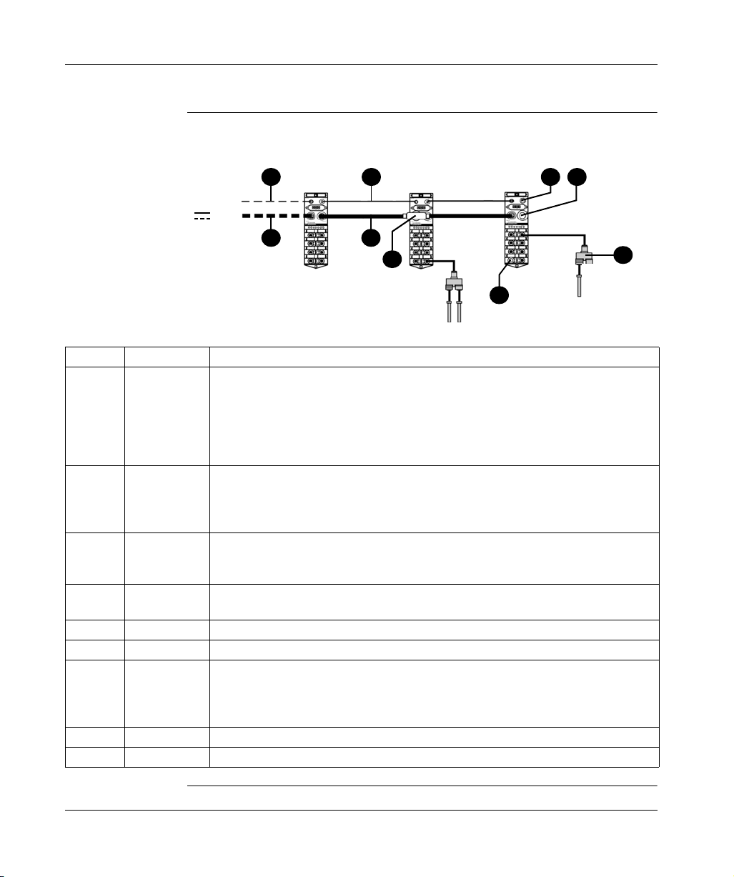
Overview of the Accessories Range
Introduction
Cables for
Connecting the
Bus to the
Splitter Box
Different cables can be used to connect the splitter box to the field bus. These are
available in different lengths.
4
1
6
8
24 V
3 2
5
FTB 1CN
9
Element Reference Function
1 FTX CN3203
FTX CN3206
FTX CN3210
FTX CN3220
FTX CN3230
FTX CN3250
2 FTX DP2206
FTX DP2210
FTX DP2220
FTX DP2250
3 FTX DP2115
FTX DP2130
FTX DP2150
4 FTXCN12M5
FTXCN12F5
5 FTXCNCT1 Connection T fitted with 2 7/8-type connectors, 5 pins, for power supply cables.
6 FTX CNTL12 Line terminators fitted with 1 M12-type connector.
7 FTX CY1208
FTX CY1212
8 FTX C78B Sealing plug for 7/8 connector.
9 FTX CM12B Sealing plugs for M12-type connectors.
Cables fitted with 2 M12-type elbow connectors, 5 pins, at both ends for connecting the
bus between two splitter boxes.
Cables fitted with 2 7/8-type connectors, 5 pins, at both ends for daisy-chaining 24 VDC
supplies to two splitter boxes.
Cables fitted with 1 7/8-type connector, 5 pins, with one free end and the other for
connecting 24 VDC supplies.
Male and female M12-type connectors, 5 pins, for CANopen bus cables (encoding A).
Distribution Y for connecting 2 M8-type connectors to the M12 connector of the splitter
box.
Distribution Y for connecting 2 M12-type connectors to the M12 connector of the splitter
box.
7
1606218 02 08/2006 13

Introduction
14
1606218 02 08/2006

Installation
2
Presentation
Introduction This chapter provides all required information for installing an FTB splitter box on a
field bus.
Note: The graphic representations of the splitter boxes in this chapter may not
correspond to those really used. However, the dimensions are exact whatever the
case.
What's in this
Chapter?
1606218 02 08/2006 15
This chapter contains the following topics:
Topic Page
Overview 16
Installing the Unit 17
Grounding of the Advantys FTB Splitter Box 21
EMC Compatibility 23

Installation
Overview
Introduction This section gives a detailed technical description of the Advantys FTB CANopen
splitter box.
Description The illustrations below show the plastic units (left) and metal units (right) of the
Advantys FTB CANopen splitter.
1
1
2
2
3
3
4
5
6
9
7
8
1
Element Function
1 Mounting holes
2 M12 connector for the inputs and outputs
3 Label
4 Display elements (diagnostics and status LED)
5 Power supply connectors (PWR IN)
6 Power supply distribution connector (PWR OUT)
7 Bus connector (BUS IN)
8 Bus connector (BUS OUT)
9 Transmission speed and addressing rotary selector switch
4
5
6
9
7
8
1
16
1606218 02 08/2006

Installation
Installing the Unit
Introduction This section gives a detailed technical description of Advantys FTB splitter boxes.
Description The Advantys FTB splitter box can be mounted directly onto a wall or a machine.
Two mounting holes have been provided for this purpose inside the splitter box.
Note: When mounting the unit, the support must be flat and smooth so as to
prevent any undue stress on the unit, which may lead to a loss of sealing.
Types of Screws
and Tightening
Torques
Plastic unit
The plastic splitter box is mounted using two 4 mm (0.16 in.) diameter screws and
two washers. The tightening torque is 1.5 Nm (13.3 lb-in).
Metal unit
The metal splitter box is mounted using two 6 mm (0.24 in.) diameter screws and
two washers. The tightening torque is 9 Nm (79.7 lb-in).
Note: For metal units, wire the ground terminal before attaching the splitter box to
its support. See Grounding of the Advantys FTB Splitter Box, p. 21.
1606218 02 08/2006 17

Installation
Plastic Unit
Dimensions
The dimensions of the plastic unit (front and side views) are given in the following
illustrations:
18
1606218 02 08/2006

Installation
Metal Unit
Dimensions
The dimensions of the metal unit (front and side views) are given in the following
illustrations:
1606218 02 08/2006 19

Installation
Method Follow the steps below:
Step Action
1 Position the splitter box on the support.
2 Mount the splitter box using the screws and washers.
RISK OF EQUIPMENT DAMAGE AND NON-COMPLIANCE WITH IP67.
Unused connectors must not be left unprotected. If a connector is not correctly
connected to the end of another connector or to a standard cable, fit a sealing plug
in order to ensure that the product is IP67 standard compliant. To ensure the IP67
protection index, check that the cover is screwed onto the base splitter box and that
all connectors are fitted with cables or sealing plugs.
Failure to follow this instruction can result in injury or equipment damage.
CAUTION
20
1606218 02 08/2006

Installation
Grounding of the Advantys FTB Splitter Box
Description The ground connection is connected internally to pin 1 of the M12 connector of the
field bus connector.
WARNING
RISK OF UNINTENDED EQUIPMENT OPERATION
Check that the splitter box is correctly connected to the earth in compliance with
the instructions provided in his section. If the splitter box is not grounded, or if the
ground connection is made with an unsuitable cable, the product will be sensitive
to electromagnetic disturbances. See EMC Compatibility, p. 23.
Failure to follow this instruction can result in death, serious injury, or
equipment damage.
Position of the
Ground
Electrode on the
Plastic Unit
The following figure shows the position of the ground electrode on the plastic boxes.
Note: Use a grounding strip or a conductor with a cross-section of 1 to 1.5 mm2
(AWG18, AWG16) and a length of ≤ 3 m (9.84 ft) long. The maximum
recommended length for the grounding strip is 3 m (9.84 ft).
1606218 02 08/2006 21

Installation
Method for
Plastic Units
Position of the
Ground
Electrode on the
Metal Unit
Follow the steps below to connect the ground to the unit:
Step Action
1 Remove the label located above the symbol representing the ground.
2 Insert the end of the grounding strip into the grounding terminal of the splitter
box.
3 Screw in the ground connection screw.
The following figure shows the position of the ground electrode on the metal boxes.
Note: Use a grounding strip or a conductor with a cross-section of 1 to 1.5 mm2
(AWG18, AWG16) and a length of ≤ 3 m (9.84 ft) long. The maximum
recommended length for the grounding strip is 3 m (9.84 ft).
Method for Metal
Units
Mounting the
Metal Unit
22
Follow the steps below to connect the unit to the ground electrode:
Step Action
1 Crimp the lug on the ground cable.
2 Screw in the lug with the ground conductor connection screw (supplied with the
product).
Once these steps have all been completed (see table above), the product can be
mounted on its support.
1606218 02 08/2006

EMC Compatibility
Installation
Product
Compliance
This product complies with the European directive 89/336/CEE on "electromagnetic
compatibility".
The products described in this manual meet all the conditions regarding
electromagnetic compatibility and are compliant with the applicable standards.
However, this does not mean that the electromagnetic compatibility of your
installation is assured.
This is why it is strongly recommended to follow all indications concerning an EMC
compliant installation. Only in these conditions and thanks to the exclusive use of
CE approved components, will the devices used be deemed as compliant with the
EMC directives.
When handling the products, ensure that all safety measures related to
electromagnetic compatibility and all conditions for the use of the products are
complied with by all persons concerned. This is especially important when handling
products sensitive to electrostatic discharges.
WARNING
RISK OF ELECTROMAGNETIC INTERFERENCE AND UNINTENDED
EQUIPMENT OPERATION
The products described in this manual contain highly complex semiconductors that
can be damaged or destroyed by electrostatic discharges (ESD). If, for example,
they are used within the vicinity of devices rated as class A or B according to IEC
6100-4-4, the level of electromagnetic interference may be enough to cause the
device to operate unexpectedly, and/or to damage it.
Damage may not necessarily cause a failure or malfunction that is immediately
detectable. It may occur sporadically or in a delayed manner.
If there is a risk of electromagnetic interference, the system designer must
implement the necessary protective measures.
Failure to follow this instruction can result in death, serious injury, or
equipment damage.
1606218 02 08/2006 23

Installation
Grounding A low impedance connection with a maximum length of 3 m (9.84 ft) must be
installed between the splitter box's ground electrode and the reference ground in
order to discharge the noise voltages. The inductance of standard grounding cables
(PE) presents a risk of high impedance when high frequency noise voltages are
present. It is therefore advisable to use grounding strips. If this solution is not
possible, use a ground conductor with a large cable cross-section and a ground
connection that is as short as possible.
WARNING
RISK OF UNINTENDED EQUIPMENT OPERATION
If the box is not connected to the ground, or if the ground connection is made using
an inappropriate cable, the product will be sensitive to electromagnetic
disturbances. This may lead to unexpected equipment operation.
Failure to follow this instruction can result in death, serious injury, or
equipment damage.
Cable Routing Make sure that the following basic wiring rules are followed:
Keep the data wire and the power cables apart from one another, in so far as is
possible.
Make sure there is a space of at least 10 cm (3.94 inches) between the data wires
and the power cables.
The data wires and power cables must only cross at a right angle to one another.
It is advisable to route the data wires and power cables through separate shielded
ducts.
When laying the cables, the noise voltage from other devices or wires must be
considered. This particularly applies to frequency converters, motors and other
devices or cables generating high frequency disturbances. High frequency
sources and the cables described in this manual must be as far apart from each
other as possible.
24
WARNING
RISK OF UNINTENDED EQUIPMENT OPERATION
Please read and comply with the cabling rules listed above. Failure to comply with
these wiring rules is a common cause of EMC problems! This may lead to
unexpected equipment operation.
Failure to follow this instruction can result in death, serious injury, or
equipment damage.
1606218 02 08/2006

Installation
Control of
Inductive Loads
The outputs of the devices described in this manual are equipped with an integrated
protective system against the high noise voltages that may be generated by
inductive loads.
Integrated protective system against the high noise voltages generated by inductive
loads
Varistor
Inductive load
e.g. electromagnetic
valve
The varistor rapidly discharges the energy accumulated in the magnetic field of the
inductive load.
The high voltages arising from the disconnection of inductive loads create large
fields in the wires that may cause disturbances in nearby circuits or devices. It is
advisable to provide an anti-interference device at the load level. In this way, the
voltage peak generated by the inductive load is short-circuited directly at the point
at which it occurs.
1606218 02 08/2006 25

Installation
26
1606218 02 08/2006

Splitter Box Characteristics and Wiring
3
Presentation
Introduction This chapter provides an overall description of all Advantys FTB splitter boxes.
Note: The "-" in the tables corresponds to values that are not applicable.
What's in this
Chapter?
This chapter contains the following topics:
Topic Page
Advantys FTB Splitter Box Environment Properties 28
Electrical Characteristics 29
Connecting the Actuators and Sensors 30
Power Supply Connection 32
1606218 02 08/2006 27

Splitter Box Characteristics and Wiring
Advantys FTB Splitter Box Environment Properties
Environment
Properties
Characteristic Description Reference standard
Product certification cULus -
Operating temperature -20°C...+60°C (-4°F...+140°F) -
Storage temperature -25°C...+70°C (-13°F...+158°F) -
Degree of protection IP67 According to IEC 60529
Altitude 0m 2,000 m (6,561 ft) -
Vibration withstand capacity
for plastic units
Constant amplitude: 0.35 mm (0.0138 in)
10 Hz≤ f ≤ 57 Hz
Constant acceleration: 5.0 gn
57 Hz≤ f ≤ 150 Hz
Vibration resistance capacity
for metal units
Constant amplitude: 1.5 mm (0.06 in)
5 Hz ≤ f ≤ 70 Hz
Constant acceleration: 15 gn
70 Hz ≤ f ≤ 500 Hz
Shock resistance capacity for
30 gn, duration: 11 ms According to IEC 68-2-27, Fc
plastic units
Shock withstand capacity for
50 gn, duration: 11 ms -
metal units
Resistance capacity for
electrostatic discharges
Withstand capacity for
Contact: +/- 4 kV
Air: +/- 8kV
10 V/m (3.05 V/ft) According to IEC 61000-4-3
radiated fields
Withstand capacity for fast
transients
Withstand capacity for surge
Withstand capacity for duct
Power supply: +/- 2 kV
Signal: +/- 2 kV
Power supply:
symmetrical: +/-500VDC
asymmetrical: +/-1,000 VDC
Signals:
symmetrical: +/-500VDC
asymmetrical: +/-1,000 VDC
Ground : +/-500VDC
10 Vrms According to IEC 61000-4-6
fields
Withstand capacity for 50 Hz
30 A/m (9.15 A/ft) According to IEC 61000-4-8
magnetic fields
Mounting In all positions -
According to IEC 68-2-6, Fc
test
According to IEC 68-2-6, Fc
test
test
According to IEC 61000-4-2
According to IEC 61000-4-4
According to IEC 61000-4-5
28
1606218 02 08/2006

Electrical Characteristics
Splitter Box Characteristics and Wiring
Splitter Box
Characteristics
Input
Characteristics
Output
characteristics
Characteristic Description
Splitter box's internal consumption 120 mA
Splitter power supply voltage 18...30VDC
Splitter and sensor supply current ≤ 8 A
Actuator supply current ≤ 8 A
Under-voltage detection yes
Characteristic Description
Compliance with IEC 1131-2 Type 2
Compliance with 2-wire/3-wire sensor Yes
Rated power voltage 24 VDC
Maximum current 200 mA (for 2 diagnostics input channels)
Logic Positive PNP Sink
Filtering input 1 ms
Protection against reverse polarity and shortcircuit in sensor power supply
Overload and over-voltage protection Yes
Characteristic Description
Output type Transistors
Output voltage 24 VDC
Output current 1.6 A
Over-voltage protection Yes (transient diode)
Maximum switching cycle 20 Hz
Maximum lamp load 10 W
Connection for outputs / cable lengths
Protection against short-circuits yes
Yes
0.75mm2: 10 m maximum (AWG 19 / 32.8 ft)
0.34 mm2: 5 m maximum (AWG 23 / 16.4 ft)
1606218 02 08/2006 29

Splitter Box Characteristics and Wiring
Connecting the Actuators and Sensors
Description The actuators and sensors are connected to the FTB splitter box using M12-type
connectors.
Characteristics
of the
Connections
Assignment of
M12 Connector
Pins
The maximum admissible load for the FTB splitter boxes is limited to:
1.6 A per output (actuator current),
200 mA for both inputs (sensor current).
WARNING
RISK OF EQUIPMENT DAMAGE AND NON-COMPLIANCE WITH IP67
Unused M12 connectors must not be left unprotected. If an M12 connector is not
correctly connected to the end of another connector or standard cable, fit a sealing
plug in order to ensure that the product is IP67 standard compliant. To ensure the
IP67 protection index, check that the cover is screwed onto the base splitter box
and that all connectors are fitted with cables or sealing plugs.
Failure to follow this instruction can result in death, serious injury, or
equipment damage.
The following diagram shows the front view of a 5-pin M12 connector and the
convention for numbering the pins:
Pin Assignment
1 +24 VDC
2 Channel 10 to 17: diagnostics input or functional input or output
30 VDC
4 Channel 00 to 07: functional input or output
5 Ground
30
1606218 02 08/2006
 Loading...