


Schneider Electric Modicon M221 Hardware Guide
Modicon M221 Logic
Controller
Hardware Guide
02/2020
<![endif]>EIO0000003313.01
www.schneider-electric.com

The information provided in this documentation contains general descriptions and/or technical characteristics of the performance of the products contained herein. This documentation is not intended as a substitute for and is not to be used for determining suitability or reliability of these products for specific user applications. It is the duty of any such user or integrator to perform the appropriate and complete risk analysis, evaluation and testing of the products with respect to the relevant specific application or use thereof. Neither Schneider Electric nor any of its affiliates or subsidiaries shall be responsible or liable for misuse of the information contained herein. If you have any suggestions for improvements or amendments or have found errors in this publication, please notify us.
You agree not to reproduce, other than for your own personal, noncommercial use, all or part of this document on any medium whatsoever without permission of Schneider Electric, given in writing. You also agree not to establish any hypertext links to this document or its content. Schneider Electric does not grant any right or license for the personal and noncommercial use of the document or its content, except for a non-exclusive license to consult it on an "as is" basis, at your own risk. All other rights are reserved.
All pertinent state, regional, and local safety regulations must be observed when installing and using this product. For reasons of safety and to help ensure compliance with documented system data, only the manufacturer should perform repairs to components.
When devices are used for applications with technical safety requirements, the relevant instructions must be followed.
Failure to use Schneider Electric software or approved software with our hardware products may result in injury, harm, or improper operating results.
Failure to observe this information can result in injury or equipment damage. © 2020 Schneider Electric. All rights reserved.
2 |
EIO0000003313 02/2020 |

Table of Contents
|
Safety Information. . . . . . . . . . . . . . . . . . . . . . . . . . . . . . |
7 |
|
About the Book. . . . . . . . . . . . . . . . . . . . . . . . . . . . . . . . |
9 |
Part I Modicon M221 Logic Controller Introduction . . . . . . |
17 |
|
Chapter 1 M221 General Overview. . . . . . . . . . . . . . . . . . . . . . . . . |
19 |
|
|
TM221C Logic Controller Description . . . . . . . . . . . . . . . . . . . . . . . . . |
20 |
|
TM221M Logic Controller Description. . . . . . . . . . . . . . . . . . . . . . . . . |
25 |
|
Maximum Hardware Configuration . . . . . . . . . . . . . . . . . . . . . . . . . . . |
30 |
|
TMC2 Cartridges. . . . . . . . . . . . . . . . . . . . . . . . . . . . . . . . . . . . . . . . . |
34 |
|
TM3 Expansion Modules. . . . . . . . . . . . . . . . . . . . . . . . . . . . . . . . . . . |
36 |
|
TM2 Expansion Modules. . . . . . . . . . . . . . . . . . . . . . . . . . . . . . . . . . . |
45 |
|
Accessories. . . . . . . . . . . . . . . . . . . . . . . . . . . . . . . . . . . . . . . . . . . . . |
49 |
Chapter 2 |
M221 Features . . . . . . . . . . . . . . . . . . . . . . . . . . . . . . . . |
53 |
|
Real Time Clock (RTC) . . . . . . . . . . . . . . . . . . . . . . . . . . . . . . . . . . . . |
54 |
|
Input Management. . . . . . . . . . . . . . . . . . . . . . . . . . . . . . . . . . . . . . . . |
61 |
|
Output Management . . . . . . . . . . . . . . . . . . . . . . . . . . . . . . . . . . . . . . |
65 |
|
Run/Stop . . . . . . . . . . . . . . . . . . . . . . . . . . . . . . . . . . . . . . . . . . . . . . . |
69 |
|
SD Card . . . . . . . . . . . . . . . . . . . . . . . . . . . . . . . . . . . . . . . . . . . . . . . |
72 |
Chapter 3 |
M221 Installation . . . . . . . . . . . . . . . . . . . . . . . . . . . . . . |
79 |
3.1 M221 Logic Controller General Rules for Implementing . . . . . . . . . . . |
80 |
|
|
Environmental Characteristics. . . . . . . . . . . . . . . . . . . . . . . . . . . . . . . |
81 |
|
Certifications and Standards . . . . . . . . . . . . . . . . . . . . . . . . . . . . . . . . |
85 |
3.2 M221 Logic Controller Installation. . . . . . . . . . . . . . . . . . . . . . . . . . . . |
86 |
|
|
Installation and Maintenance Requirements . . . . . . . . . . . . . . . . . . . . |
87 |
|
TM221C Logic Controller Mounting Positions and Clearances. . . . . . |
90 |
|
TM221M Logic Controller Mounting Positions and Clearances. . . . . . |
93 |
|
Top Hat Section Rail (DIN rail) . . . . . . . . . . . . . . . . . . . . . . . . . . . . . . |
96 |
|
Installing and Removing the Controller with Expansions. . . . . . . . . . . |
100 |
|
Direct Mounting on a Panel Surface . . . . . . . . . . . . . . . . . . . . . . . . . . |
104 |
3.3 |
M221 Electrical Requirements. . . . . . . . . . . . . . . . . . . . . . . . . . . . . . . |
106 |
|
Wiring Best Practices . . . . . . . . . . . . . . . . . . . . . . . . . . . . . . . . . . . . . |
107 |
|
DC Power Supply Characteristics and Wiring. . . . . . . . . . . . . . . . . . . |
114 |
|
AC Power Supply Characteristics and Wiring . . . . . . . . . . . . . . . . . . . |
119 |
|
Grounding the M221 System. . . . . . . . . . . . . . . . . . . . . . . . . . . . . . . . |
122 |
EIO0000003313 02/2020 |
3 |

Part II Modicon TM221C Logic Controller. . . . . . . . . . . . . . |
127 |
|
Chapter 4 |
TM221C16R. . . . . . . . . . . . . . . . . . . . . . . . . . . . . . . . . . . |
129 |
|
TM221C16R Presentation . . . . . . . . . . . . . . . . . . . . . . . . . . . . . . . . . . |
129 |
Chapter 5 |
TM221CE16R. . . . . . . . . . . . . . . . . . . . . . . . . . . . . . . . . . |
135 |
|
TM221CE16R Presentation. . . . . . . . . . . . . . . . . . . . . . . . . . . . . . . . . |
135 |
Chapter 6 |
TM221C16T . . . . . . . . . . . . . . . . . . . . . . . . . . . . . . . . . . . |
139 |
|
TM221C16T Presentation . . . . . . . . . . . . . . . . . . . . . . . . . . . . . . . . . . |
139 |
Chapter 7 |
TM221CE16T. . . . . . . . . . . . . . . . . . . . . . . . . . . . . . . . . . |
143 |
|
TM221CE16T Presentation . . . . . . . . . . . . . . . . . . . . . . . . . . . . . . . . . |
143 |
Chapter 8 |
TM221C16U. . . . . . . . . . . . . . . . . . . . . . . . . . . . . . . . . . . |
147 |
|
TM221C16U Presentation . . . . . . . . . . . . . . . . . . . . . . . . . . . . . . . . . . |
147 |
Chapter 9 |
TM221CE16U. . . . . . . . . . . . . . . . . . . . . . . . . . . . . . . . . . |
151 |
|
TM221CE16U Presentation. . . . . . . . . . . . . . . . . . . . . . . . . . . . . . . . . |
151 |
Chapter 10 |
TM221C24R. . . . . . . . . . . . . . . . . . . . . . . . . . . . . . . . . . . |
157 |
|
TM221C24R Presentation . . . . . . . . . . . . . . . . . . . . . . . . . . . . . . . . . . |
157 |
Chapter 11 |
TM221CE24R. . . . . . . . . . . . . . . . . . . . . . . . . . . . . . . . . . |
161 |
|
TM221CE24R Presentation. . . . . . . . . . . . . . . . . . . . . . . . . . . . . . . . . |
161 |
Chapter 12 |
TM221C24T . . . . . . . . . . . . . . . . . . . . . . . . . . . . . . . . . . . |
165 |
|
TM221C24T Presentation . . . . . . . . . . . . . . . . . . . . . . . . . . . . . . . . . . |
165 |
Chapter 13 |
TM221CE24T. . . . . . . . . . . . . . . . . . . . . . . . . . . . . . . . . . |
169 |
|
TM221CE24T Presentation . . . . . . . . . . . . . . . . . . . . . . . . . . . . . . . . . |
169 |
Chapter 14 |
TM221C24U. . . . . . . . . . . . . . . . . . . . . . . . . . . . . . . . . . . |
173 |
|
TM221C24U Presentation . . . . . . . . . . . . . . . . . . . . . . . . . . . . . . . . . . |
173 |
Chapter 15 |
TM221CE24U. . . . . . . . . . . . . . . . . . . . . . . . . . . . . . . . . . |
179 |
|
TM221CE24U Presentation. . . . . . . . . . . . . . . . . . . . . . . . . . . . . . . . . |
179 |
Chapter 16 |
TM221C40R. . . . . . . . . . . . . . . . . . . . . . . . . . . . . . . . . . . |
185 |
|
TM221C40R Presentation . . . . . . . . . . . . . . . . . . . . . . . . . . . . . . . . . . |
185 |
Chapter 17 |
TM221CE40R. . . . . . . . . . . . . . . . . . . . . . . . . . . . . . . . . . |
191 |
|
TM221CE40R Presentation. . . . . . . . . . . . . . . . . . . . . . . . . . . . . . . . . |
191 |
Chapter 18 |
TM221C40T . . . . . . . . . . . . . . . . . . . . . . . . . . . . . . . . . . . |
197 |
|
TM221C40T Presentation . . . . . . . . . . . . . . . . . . . . . . . . . . . . . . . . . . |
197 |
Chapter 19 |
TM221CE40T. . . . . . . . . . . . . . . . . . . . . . . . . . . . . . . . . . |
203 |
|
TM221CE40T Presentation . . . . . . . . . . . . . . . . . . . . . . . . . . . . . . . . . |
203 |
Chapter 20 |
TM221C40U. . . . . . . . . . . . . . . . . . . . . . . . . . . . . . . . . . . |
209 |
|
TM221C40U Presentation . . . . . . . . . . . . . . . . . . . . . . . . . . . . . . . . . . |
209 |
Chapter 21 |
TM221CE40U. . . . . . . . . . . . . . . . . . . . . . . . . . . . . . . . . . |
215 |
|
TM221CE40U Presentation. . . . . . . . . . . . . . . . . . . . . . . . . . . . . . . . . |
215 |
4 |
EIO0000003313 02/2020 |

Chapter 22 Embedded I/O Channels . . . . . . . . . . . . . . . . . . . . . . . . |
221 |
|
|
Digital Inputs . . . . . . . . . . . . . . . . . . . . . . . . . . . . . . . . . . . . . . . . . . . . |
222 |
|
Relay Outputs . . . . . . . . . . . . . . . . . . . . . . . . . . . . . . . . . . . . . . . . . . . |
239 |
|
Regular and Fast Transistor Outputs . . . . . . . . . . . . . . . . . . . . . . . . . |
247 |
|
Analog Inputs . . . . . . . . . . . . . . . . . . . . . . . . . . . . . . . . . . . . . . . . . . . |
256 |
Part III Modicon TM221M Logic Controller. . . . . . . . . . . . . . |
261 |
|
Chapter 23 TM221M16R / TM221M16RG . . . . . . . . . . . . . . . . . . . . |
263 |
|
|
TM221M16R / TM221M16RG Presentation . . . . . . . . . . . . . . . . . . . . |
264 |
|
TM221M16R / TM221M16RG Digital Inputs . . . . . . . . . . . . . . . . . . . . |
268 |
|
TM221M16R / TM221M16RG Digital Outputs. . . . . . . . . . . . . . . . . . . |
272 |
|
TM221M16R / TM221M16RG Analog Inputs . . . . . . . . . . . . . . . . . . . |
276 |
Chapter 24 TM221ME16R / TM221ME16RG . . . . . . . . . . . . . . . . . . |
281 |
|
|
TM221ME16R / TM221ME16RG Presentation. . . . . . . . . . . . . . . . . . |
282 |
|
TM221ME16R / TM221ME16RG Digital Inputs. . . . . . . . . . . . . . . . . . |
287 |
|
TM221ME16R / TM221ME16RG Digital Outputs . . . . . . . . . . . . . . . . |
291 |
|
TM221ME16R / TM221ME16RG Analog Inputs . . . . . . . . . . . . . . . . . |
295 |
Chapter 25 TM221M16T / TM221M16TG. . . . . . . . . . . . . . . . . . . . . |
299 |
|
|
TM221M16T / TM221M16TG Presentation. . . . . . . . . . . . . . . . . . . . . |
300 |
|
TM221M16T / TM221M16TG Digital Inputs . . . . . . . . . . . . . . . . . . . . |
304 |
|
TM221M16T / TM221M16TG Digital Outputs . . . . . . . . . . . . . . . . . . . |
309 |
|
TM221M16T / TM221M16TG Analog Inputs. . . . . . . . . . . . . . . . . . . . |
314 |
Chapter 26 TM221ME16T / TM221ME16TG . . . . . . . . . . . . . . . . . . |
319 |
|
|
TM221ME16T / TM221ME16TG Presentation . . . . . . . . . . . . . . . . . . |
320 |
|
TM221ME16T / TM221ME16TG Digital Inputs . . . . . . . . . . . . . . . . . . |
326 |
|
TM221ME16T / TM221ME16TG Digital Outputs. . . . . . . . . . . . . . . . . |
331 |
|
TM221ME16T / TM221ME16TG Analog Inputs . . . . . . . . . . . . . . . . . |
336 |
Chapter 27 |
TM221M32TK. . . . . . . . . . . . . . . . . . . . . . . . . . . . . . . . . |
341 |
|
TM221M32TK Presentation. . . . . . . . . . . . . . . . . . . . . . . . . . . . . . . . . |
342 |
|
TM221M32TK Digital Inputs . . . . . . . . . . . . . . . . . . . . . . . . . . . . . . . . |
346 |
|
TM221M32TK Digital Outputs. . . . . . . . . . . . . . . . . . . . . . . . . . . . . . . |
351 |
|
TM221M32TK Analog Inputs. . . . . . . . . . . . . . . . . . . . . . . . . . . . . . . . |
356 |
Chapter 28 |
TM221ME32TK. . . . . . . . . . . . . . . . . . . . . . . . . . . . . . . . |
361 |
|
TM221ME32TK Presentation . . . . . . . . . . . . . . . . . . . . . . . . . . . . . . . |
362 |
|
TM221ME32TK Digital Inputs . . . . . . . . . . . . . . . . . . . . . . . . . . . . . . . |
367 |
|
TM221ME32TK Digital Outputs. . . . . . . . . . . . . . . . . . . . . . . . . . . . . . |
372 |
|
TM221ME32TK Analog Inputs . . . . . . . . . . . . . . . . . . . . . . . . . . . . . . |
377 |
EIO0000003313 02/2020 |
5 |

Part IV Modicon M221 Logic Controller Communication . . . |
381 |
Chapter 29 Integrated Communication Ports . . . . . . . . . . . . . . . . . . . |
383 |
USB Mini-B Programming Port . . . . . . . . . . . . . . . . . . . . . . . . . . . . . . |
384 |
Ethernet Port . . . . . . . . . . . . . . . . . . . . . . . . . . . . . . . . . . . . . . . . . . . . |
386 |
Serial Line 1 . . . . . . . . . . . . . . . . . . . . . . . . . . . . . . . . . . . . . . . . . . . . |
389 |
Serial Line 2. . . . . . . . . . . . . . . . . . . . . . . . . . . . . . . . . . . . . . . . . . . . . |
393 |
Chapter 30 Connecting the M221 Logic Controller to a PC . . . . . . . . |
397 |
Connecting the Controller to a PC . . . . . . . . . . . . . . . . . . . . . . . . . . . . |
397 |
Glossary . . . . . . . . . . . . . . . . . . . . . . . . . . . . . . . . . . . . . . . . . |
401 |
Index . . . . . . . . . . . . . . . . . . . . . . . . . . . . . . . . . . . . . . . . . |
407 |
6 |
EIO0000003313 02/2020 |

Safety Information
Important Information
NOTICE
Read these instructions carefully, and look at the equipment to become familiar with the device beforetryingtoinstall,operate,service,ormaintainit.Thefollowingspecialmessagesmayappear throughout this documentation or on the equipment to warn of potential hazards or to call attention to information that clarifies or simplifies a procedure.
EIO0000003313 02/2020 |
7 |

PLEASE NOTE
Electrical equipment should be installed, operated, serviced, and maintained only by qualified personnel.No responsibility is assumed by Schneider Electricfor any consequences arising out of the use of this material.
A qualified person is one who has skills and knowledge related to the construction and operation of electrical equipment and its installation, and has received safety training to recognize and avoid the hazards involved.
QUALIFICATION OF PERSONNEL
Only appropriately trained persons who are familiar with and understand the contents of this manual and all other pertinent product documentation are authorized to work on and with this product.
Thequalifiedpersonmustbeabletodetectpossiblehazardsthatmayarisefromparameterization, modifying parameter values and generally from mechanical, electrical, or electronic equipment. The qualified person must be familiar with the standards, provisions, and regulations for the prevention of industrial accidents, which they must observe when designing and implementing the system.
INTENDED USE
The products described or affected by this document, together with software, accessories, and options, are programmable logic controllers (referred to herein as “logic controllers”), intended for industrial useaccording to theinstructions, directions,examples,andsafetyinformation contained in the present document and other supporting documentation.
The product may only be used in compliance with all applicable safety regulations and directives, the specified requirements, and the technical data.
Prior to using the product, you must perform a risk assessment in view of the planned application. Based on the results, the appropriate safety-related measures must be implemented.
Since the product is used as a component in an overall machine or process, you must ensure the safety of persons by means of the design of this overall system.
Operatetheproductonlywiththespecifiedcablesandaccessories.Useonlygenuineaccessories and spare parts.
Any use other than the use explicitly permitted is prohibited and can result in unanticipated hazards.
8 |
EIO0000003313 02/2020 |

About the Book
At a Glance
Document Scope
Use this document to:
Install and operate your M221 Logic Controller.
Connect the M221 Logic Controller to a programming device equipped with EcoStruxure Machine Expert - Basic software.
Interface the M221 Logic Controller with I/O expansion modules, HMI and other devices.
Familiarize yourself with the M221 Logic Controller features.
NOTE: Read and understand this document and all related documents (see page 10) before installing, operating, or maintaining your controller.
Validity Note
This document has been updated for the release of EcoStruxureTM Machine Expert - Basic V1.1. The technical characteristics of the devices described in this manual also appear online.
The characteristics that are presented in the present document should be the same as those characteristics that appear online. In line with our policy of constant improvement, we may revise content over time to improve clarity and accuracy. If you see a difference between the document and online information, use the online information as your reference.
For product compliance and environmental information (RoHS, REACH, PEP, EOLI, etc.), go to www.schneider-electric.com/green-premium.
EIO0000003313 02/2020 |
9 |

Related Documents
Title of Documentation |
Reference Number |
Modicon M221 Logic Controller - Programming Guide |
EIO0000003297 (ENG) |
|
EIO0000003298 (FRE) |
|
EIO0000003299 (GER) |
|
EIO0000003300 (SPA) |
|
EIO0000003301 (ITA) |
|
EIO0000003302 (CHS) |
|
EIO0000003304 (TUR) |
|
EIO0000003303 (POR) |
Modicon TMH2GDB Remote Graphic Display - User Guide |
EIO0000003321 (ENG) |
|
EIO0000003322 (FRE) |
|
EIO0000003323 (GER) |
|
EIO0000003324 (SPA) |
|
EIO0000003325 (ITA) |
|
EIO0000003326 (CHS) |
|
EIO0000003328 (TUR) |
|
EIO0000003327 (POR) |
Modicon TMC2 Cartridges - Hardware Guide |
EIO0000003337 (ENG) |
|
EIO0000003338 (FRE) |
|
EIO0000003339 (GER) |
|
EIO0000003340 (SPA) |
|
EIO0000003341 (ITA) |
|
EIO0000003342 (CHS) |
|
EIO0000003344 (TUR) |
|
EIO0000003343 (POR) |
Modicon TM3 Digital I/O Modules - Hardware Guide |
EIO0000003125 (ENG) |
|
EIO0000003126 (FRE) |
|
EIO0000003127 (GER) |
|
EIO0000003128 (SPA) |
|
EIO0000003129 (ITA) |
|
EIO0000003130 (CHS) |
|
EIO0000003425 (TUR) |
|
EIO0000003424 (POR) |
Modicon TM3 Analog I/O Modules - Hardware Guide |
EIO0000003131 (ENG) |
|
EIO0000003132 (FRE) |
|
EIO0000003133 (GER) |
|
EIO0000003134 (SPA) |
|
EIO0000003135 (ITA) |
|
EIO0000003136 (CHS) |
|
EIO0000003427 (TUR) |
|
EIO0000003426 (POR) |
10 |
EIO0000003313 02/2020 |
Title of Documentation |
Reference Number |
Modicon TM3 Expert I/O Modules - Hardware Guide |
EIO0000003137 (ENG) |
|
EIO0000003138 (FRE) |
|
EIO0000003139 (GER) |
|
EIO0000003140 (SPA) |
|
EIO0000003141 (ITA) |
|
EIO0000003142 (CHS) |
|
EIO0000003429 (TUR) |
|
EIO0000003428 (POR) |
Modicon TM3 Safety Modules - Hardware Guide |
EIO0000003353 (ENG) |
|
EIO0000003354 (FRE) |
|
EIO0000003355 (GER) |
|
EIO0000003356 (SPA) |
|
EIO0000003357 (ITA) |
|
EIO0000003358 (CHS) |
|
EIO0000003360 (TUR) |
|
EIO0000003359 (POR) |
Modicon TM3 Transmitter and Receiver Modules - Hardware Guide |
EIO0000003143 (ENG) |
|
EIO0000003144 (FRE) |
|
EIO0000003145 (GER) |
|
EIO0000003146 (SPA) |
|
EIO0000003147 (ITA) |
|
EIO0000003148 (CHS) |
|
EIO0000003431 (TUR) |
|
EIO0000003430 (POR) |
TM221C DC Logic Controller - Instruction Sheet |
EAV48550 |
TM221C AC Logic Controller - Instruction Sheet |
EAV58623 |
TM221M Logic Controller - Instruction Sheet |
HRB59602 |
You can download these technical publications and other technical information from our website at https://www.se.com/ww/en/download/ .
EIO0000003313 02/2020 |
11 |

Product Related Information

 DANGER
HAZARD OF ELECTRIC SHOCK, EXPLOSION OR ARC FLASH
Disconnect all power from all equipment including connected devices prior to removing any covers or doors, or installing or removing any accessories, hardware, cables, or wires except under the specific conditions specified in the appropriate hardware guide for this equipment.
Alwaysuseaproperlyratedvoltagesensingdevicetoconfirmthepowerisoffwhereandwhen indicated.
Replace and secure all covers, accessories, hardware, cables, and wires and confirm that a proper ground connection exists before applying power to the unit.
Use only the specified voltage when operating this equipment and any associated products.
Failure to follow these instructions will result in death or serious injury.
 DANGER
POTENTIAL FOR EXPLOSION
Only use this equipment in non-hazardous locations, or in locations that comply with Class I, Division 2, Groups A, B, C and D.
Do not substitute components which would impair compliance to Class I, Division 2.
Do not connect or disconnect equipment unless power has been removed or the location is known to be non-hazardous.
Do not use the USB port(s), if so equipped, unless the location is known to be non-hazardous.
Failure to follow these instructions will result in death or serious injury.
12 |
EIO0000003313 02/2020 |

 WARNING
LOSS OF CONTROL
The designerof anycontrolscheme mustconsiderthe potential failure modes ofcontrol paths and, for certain critical control functions, provide a means to achieve a safe state during and after a path failure. Examples of critical control functions are emergency stop and overtravel stop, power outage and restart.
Separate or redundant control paths must be provided for critical control functions.
System control paths may include communication links. Consideration must be given to the implications of unanticipated transmission delays or failures of the link.
Observe all accident prevention regulations and local safety guidelines.1
Each implementation of this equipment must be individually and thoroughly tested for proper operation before being placed into service.
Failure to follow these instructions can result in death, serious injury, or equipment damage.
1 For additional information, refer to NEMA ICS 1.1 (latest edition), "Safety Guidelines for the Application, Installation, and Maintenance of Solid State Control" and to NEMA ICS 7.1 (latest edition), "Safety Standards for Construction and Guide for Selection, Installation and Operation of Adjustable-Speed Drive Systems" or their equivalent governing your particular location.
 WARNING
UNINTENDED EQUIPMENT OPERATION
Only use software approved by Schneider Electric for use with this equipment.
Update your application program every time you change the physical hardware configuration.
Failure to follow these instructions can result in death, serious injury, or equipment damage.
EIO0000003313 02/2020 |
13 |

Terminology Derived from Standards
The technical terms, terminology, symbols and the corresponding descriptions in this manual, or that appear in or on the products themselves, are generally derived from the terms or definitions of international standards.
Intheareaoffunctionalsafetysystems,drivesandgeneral automation,thismayinclude,butisnot limited to, terms such as safety, safety function, safe state, fault, fault reset, malfunction, failure, error, error message, dangerous, etc.
Among others, these standards include:
Standard |
Description |
IEC 61131-2:2007 |
Programmable controllers, part 2: Equipment requirements and tests. |
ISO 13849-1:2015 |
Safety of machinery: Safety related parts of control systems. |
|
General principles for design. |
EN 61496-1:2013 |
Safety of machinery: Electro-sensitive protective equipment. |
|
Part 1: General requirements and tests. |
ISO 12100:2010 |
Safety of machinery - General principles for design - Risk assessment and risk |
|
reduction |
EN 60204-1:2006 |
Safety of machinery - Electrical equipment of machines - Part 1: General |
|
requirements |
ISO 14119:2013 |
Safety of machinery - Interlocking devices associated with guards - Principles |
|
for design and selection |
ISO 13850:2015 |
Safety of machinery - Emergency stop - Principles for design |
IEC 62061:2015 |
Safety of machinery - Functional safety of safety-related electrical, electronic, |
|
and electronic programmable control systems |
IEC 61508-1:2010 |
Functional safety of electrical/electronic/programmable electronic safety- |
|
related systems: General requirements. |
IEC 61508-2:2010 |
Functional safety of electrical/electronic/programmable electronic safety- |
|
related systems: Requirements for electrical/electronic/programmable |
|
electronic safety-related systems. |
IEC 61508-3:2010 |
Functional safety of electrical/electronic/programmable electronic safety- |
|
related systems: Software requirements. |
IEC 61784-3:2016 |
Industrial communication networks - Profiles - Part 3: Functional safety |
|
fieldbuses - General rules and profile definitions. |
2006/42/EC |
Machinery Directive |
2014/30/EU |
Electromagnetic Compatibility Directive |
2014/35/EU |
Low Voltage Directive |
14 |
EIO0000003313 02/2020 |

In addition, terms used in the present document may tangentially be used as theyare derived from other standards such as:
Standard |
Description |
IEC 60034 series |
Rotating electrical machines |
IEC 61800 series |
Adjustable speed electrical power drive systems |
IEC 61158 series |
Digital data communications for measurement and control – Fieldbus for use in |
|
industrial control systems |
Finally, the term zone of operation may be used in conjunction with the description of specific hazards, and is defined as it is for a hazard zone or danger zone in the Machinery Directive (2006/42/EC) and ISO 12100:2010.
NOTE: The aforementioned standards may or may not apply to the specific products cited in the presentdocumentation.Formoreinformationconcerningtheindividualstandardsapplicabletothe products described herein, see the characteristics tables for those product references.
EIO0000003313 02/2020 |
15 |

16 |
EIO0000003313 02/2020 |

Part I
Modicon M221 Logic Controller Introduction
What Is in This Part?
This part contains the following chapters:
Chapter |
|
Chapter Name |
Page |
1 |
M221 |
General Overview |
19 |
2 |
M221 |
Features |
53 |
3 |
M221 |
Installation |
79 |
EIO0000003313 02/2020 |
17 |

Modicon M221 Logic Controller Introduction
18 |
EIO0000003313 02/2020 |

Chapter 1
M221 General Overview
Overview
This chapter provides general information about the M221 Logic Controller system architecture and its components.
What Is in This Chapter?
This chapter contains the following topics:
Topic |
Page |
TM221C Logic Controller Description |
20 |
TM221M Logic Controller Description |
25 |
Maximum Hardware Configuration |
30 |
TMC2 Cartridges |
34 |
TM3 Expansion Modules |
36 |
TM2 Expansion Modules |
45 |
Accessories |
49 |
EIO0000003313 02/2020 |
19 |

M221 General Overview
TM221C Logic Controller Description
Overview
The TM221C Logic Controller has various powerful features and can service a wide range of applications.
Software configuration, programming, and commissioning are accomplished with the EcoStruxure Machine Expert - Basic software described in the EcoStruxure Machine Expert - Basic Operating Guide (see EcoStruxure Machine Expert -Basic, Operating Guide) and the M221 Logic Controller - Programming Guide (see Modicon M221, Logic Controller, Programming Guide).
Programming Languages
The M221 Logic Controller is configured and programmed with the EcoStruxure Machine Expert - Basic software, which supports the following IEC 61131-3 programming languages:
IL: Instruction List
LD: Ladder Diagram
Grafcet (List)
Grafcet (SFC)
Power Supply
The power supply of the TM221C Logic Controller is 24 Vdc (see page 114) or 100...240 Vac
(see page 119).
Real Time Clock
The M221 Logic Controller includes a Real Time Clock (RTC) system (see page 54).
Run/Stop
The M221 Logic Controller can be operated externally by the following:
a hardware Run/Stop switch (see page 69)
a Run/Stop (see page 69) operation by a dedicated digital input, defined in the software configuration (for more information, refer to Configuring Digital Inputs (see Modicon M221, Logic Controller, Programming Guide).)
EcoStruxure Machine Expert - Basic software (for more information, refer to Toolbar
(see EcoStruxure Machine Expert - Basic, Operating Guide)).
a TMH2GDB Remote Graphic Display (for more information, refer to Controller State Menu
(see Modicon TMH2GDB, Remote Graphic Display, User Guide)).
20 |
EIO0000003313 02/2020 |
|
|
|
M221 General Overview |
|
|
|
|
|
|
Memory |
|
|
|
|
|
This table describes the different types of memory: |
|
|
|
|
|
|
|
|
|
Memory Type |
Size |
Used to |
|
|
RAM |
512 Kbytes of RAM memory: 256 Kbytes for |
execute the application and contain data |
|
|
|
internal variables and 256 Kbytes for |
|
|
|
|
application and data. |
|
|
|
Non-volatile |
1.5 Mbytes, of which 256 Kbytes is used to |
save the application |
|
|
|
back up the application and data in case of |
|
|
|
|
power outage. |
|
|
Embedded Inputs/Outputs
The following embedded I/O types are available, depending on the controller reference:
Regular inputs
Fast inputs associated with counters
Regular sink/source transistor outputs
Fast sink/source transistor outputs associated with pulse generators
Relay outputs
Analog inputs
Removable Storage
The M221 Logic Controllers include an embedded SD card slot (see page 72).
TheModiconM221LogicControllerallowsthefollowingtypesof filemanagementwithanSDcard:
Clone management (see Modicon M221, Logic Controller, Programming Guide): back up the application, firmware, and post configuration (if it exists) of the logic controller
Firmware management (see Modicon M221, Logic Controller, Programming Guide): download firmware to the logic controller, to a TMH2GDB Remote Graphic Display , or to TM3 expansion modules
Application management (see Modicon M221, Logic Controller, Programming Guide): back up and restore the logic controller application, or copy it to another logic controller of the same reference
Post configuration management (see Modicon M221, Logic Controller, Programming Guide): add, change, or delete the post configuration file of the logic controller
Error log management (see Modicon M221, Logic Controller, Programming Guide): back up or delete the error log file of the logic controller
Memory management: back up and restore memory bits and words from a controller
Embedded Communication Features
The following types of communication ports are available depending on the controller reference:
Ethernet (see page 386)
USB Mini-B (see page 384)
Serial Line 1 (see page 389)
EIO0000003313 02/2020 |
21 |

M221 General Overview
Remote Graphic Display
For more information, refer to the Modicon TMH2GDB Remote Graphic Display - User Guide.
TM221C Logic Controller
Reference |
Digital Inputs |
Digital Outputs |
Analog |
Communication |
Power Supply |
|
|
|
Inputs |
Ports |
|
TM221C16R |
5 regular inputs(1) |
7 relay outputs |
Yes |
1 serial line port |
100...240 Vac |
(see page 129) |
4 fast inputs |
|
|
1 USB programming |
|
|
(HSC)(2) |
|
|
port |
|
TM221CE16R |
|
Yes |
1 serial line port |
|
|
|
|
|
|||
(see page 135) |
|
|
|
1 USB programming |
|
|
|
|
|
port |
|
|
|
|
|
1 Ethernet port |
|
TM221C16T |
5 regular inputs(1) |
Source outputs |
Yes |
1 serial line port |
24 Vdc |
(see page 139) |
4 fast inputs |
5 regular transistor outputs |
|
1 USB programming |
|
|
(HSC)(2) |
2 fast outputs |
|
port |
|
TM221CE16T |
(PLS/PWM/PTO/FREQGEN)(3) |
Yes |
1 serial line port |
|
|
|
|
||||
(see page 143) |
|
|
|
1 USB programming |
|
|
|
|
|
port |
|
|
|
|
|
1 Ethernet port |
|
TM221C16U |
5 regular inputs(1) |
Sink outputs |
Yes |
1 serial line port |
24 Vdc |
(see page 147) |
4 fast inputs |
5 regular transistor outputs |
|
1 USB programming |
|
|
(HSC)(2) |
2 fast outputs |
|
port |
|
TM221CE16U |
(PLS/PWM/PTO/FREQGEN)(3) |
|
1 serial line port |
|
|
|
|
|
|||
(see page 151) |
|
|
|
1 USB programming |
|
|
|
|
|
port |
|
|
|
|
|
1 Ethernet port |
|
NOTE: The TM221C Logic Controller uses removable screw terminal blocks.
(1) The regular inputs have a maximum frequency of 5 kHz.
(2) The fast inputs can be used either as regular inputs or as fast inputs for counting or event functions.
(3) The fast transistor outputs can be used either as regular transistor outputs, for PLS, PWM, PTO, or FREQGEN functions, or reflex outputs for HSC.
22 |
EIO0000003313 02/2020 |

M221 General Overview
Reference |
Digital Inputs |
Digital Outputs |
Analog |
Communication |
Power Supply |
|
|
|
|
Inputs |
Ports |
|
|
TM221C24R |
10 regular |
10 relay outputs |
Yes |
1 serial line port |
100...240 Vac |
|
(see page 157) |
inputs(1) |
|
|
1 |
USB programming |
|
|
4 fast inputs |
|
|
port |
|
|
TM221CE24R |
(HSC)(2) |
|
Yes |
1 serial line port |
|
|
(see page 161) |
|
|
|
1 USB programming |
|
|
|
|
|
|
port |
|
|
|
|
|
|
1 |
Ethernet port |
|
TM221C24T |
|
Source outputs |
Yes |
1 serial line port |
24 Vdc |
|
(see page 165) |
|
8 regular transistor outputs |
|
1 |
USB programming |
|
|
|
2 fast outputs |
|
port |
|
|
|
|
(PLS/PWM/PTO/FREQGEN)(3) |
|
|
|
|
TM221CE24T |
|
Yes |
1 serial line port |
|
||
(see page 169) |
|
|
|
1 USB programming |
|
|
|
|
|
|
port |
|
|
|
|
|
|
1 |
Ethernet port |
|
TM221C24U |
10 regular |
Sink outputs |
Yes |
1 serial line port |
24 Vdc |
|
(see page 173) |
inputs(1) |
8 regular transistor outputs |
|
1 |
USB programming |
|
|
4 fast inputs |
2 fast outputs |
|
port |
|
|
TM221CE24U |
(HSC)(2) |
(PLS/PWM/PTO/FREQGEN)(3) |
Yes |
1 serial line port |
|
|
(see page 179) |
|
|
|
1 USB programming |
|
|
|
|
|
|
port |
|
|
|
|
|
|
1 |
Ethernet port |
|
TM221C40R |
20 regular |
16 relay outputs |
Yes |
1 serial line port |
100...240 Vac |
|
(see page 185) |
inputs(1) |
|
|
1 |
USB programming |
|
|
4 fast inputs |
|
|
port |
|
|
TM221CE40R |
(HSC)(2) |
|
Yes |
1 serial line port |
|
|
(see page 191) |
|
|
|
1 USB programming |
|
|
|
|
|
|
port |
|
|
|
|
|
|
1 |
Ethernet port |
|
TM221C40T |
|
Source outputs |
Yes |
1 serial line port |
24 Vdc |
|
(see page 197) |
|
14 regular transistor outputs |
|
1 |
USB programming |
|
|
|
2 fast outputs |
|
port |
|
|
|
|
(PLS/PWM/PTO/FREQGEN)(3) |
|
|
|
|
TM221CE40T |
|
Yes |
1 serial line port |
|
||
(see page 203) |
|
|
|
1 USB programming |
|
|
|
|
|
|
port |
|
|
|
|
|
|
1 |
Ethernet port |
|
NOTE: The TM221C Logic Controller uses removable screw terminal blocks.
(1)The regular inputs have a maximum frequency of 5 kHz.
(2)The fast inputs can be used either as regular inputs or as fast inputs for counting or event functions.
(3)The fast transistor outputs can be used either as regular transistor outputs, for PLS, PWM, PTO, or FREQGEN functions, or reflex outputs for HSC.
EIO0000003313 02/2020 |
23 |
M221 General Overview
Reference |
Digital Inputs |
Digital Outputs |
Analog |
Communication |
Power Supply |
|
|
|
|
|
Inputs |
Ports |
|
TM221C40U |
20 regular |
Sink outputs |
Yes |
1 serial line port |
24 Vdc |
|
(see page 209) |
inputs(1) |
12 regular transistor outputs |
|
1 USB programming |
|
|
|
|
4 fast inputs |
4 fast outputs |
|
port |
|
TM221CE40U |
(HSC)(2) |
(PLS/PWM/PTO/FREQGEN)(3) |
Yes |
1 serial line port |
|
|
(see page 215) |
|
|
|
1 USB programming |
|
|
|
|
|
|
|
port |
|
|
|
|
|
|
1 Ethernet port |
|
NOTE: The TM221C Logic Controller uses removable screw terminal blocks. |
|
|
||||
(1) |
The regular inputs have a maximum frequency of 5 kHz. |
|
|
|
||
(2) |
The fast inputs can be used either as regular inputs or as fast inputs for counting or event functions. |
|||||
(3) |
The fast transistor outputs can be used either as regular transistor outputs, for PLS, PWM, PTO, or FREQGEN |
|||||
|
functions, or reflex outputs for HSC. |
|
|
|
||
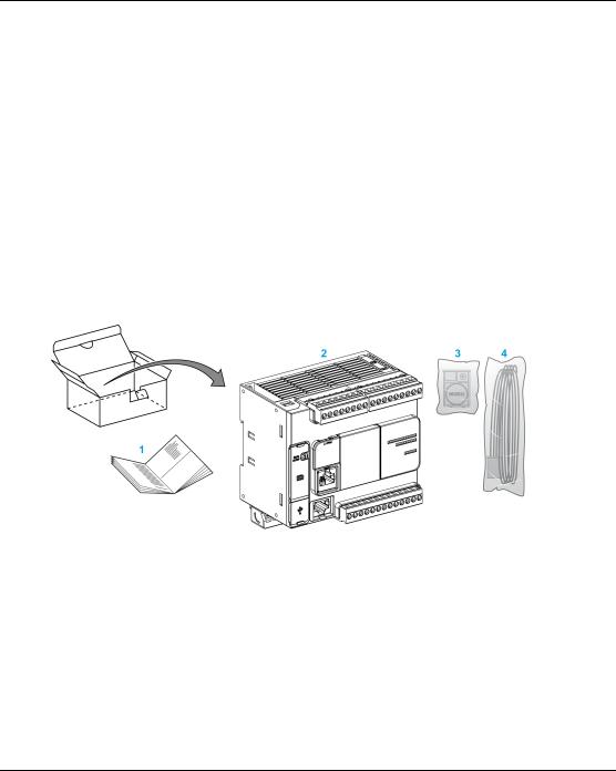
Delivery Content
The following figure presents the content of the delivery for a TM221C Logic Controller:
1 TM221C Logic Controller Instruction Sheet
2TM221C Logic Controller
3 Battery holder with lithium carbon monofluoride battery, type Panasonic BR2032.
4Analog cable
24 |
EIO0000003313 02/2020 |

M221 General Overview
TM221M Logic Controller Description
Overview
The TM221M Logic Controller has various powerful features and can service a wide range of applications.
Software configuration, programming, and commissioning are accomplished with the EcoStruxure Machine Expert - Basic software described in the EcoStruxure Machine Expert - Basic Operating Guide (see EcoStruxure Machine Expert -Basic, Operating Guide) and the M221 Logic Controller - Programming Guide (see Modicon M221, Logic Controller, Programming Guide).
Programming Languages
The M221 Logic Controller is configured and programmed with the EcoStruxure Machine Expert - Basic software, which supports the following IEC 61131-3 programming languages:
IL: Instruction List
LD: Ladder Diagram
Grafcet (List)
Grafcet (SFC)
Power Supply
The power supply of the TM221M Logic Controller is 24 Vdc (see page 114).
Real Time Clock
The M221 Logic Controller includes a Real Time Clock (RTC) system (see page 54).
Run/Stop
The M221 Logic Controller can be operated externally by the following:
a hardware Run/Stop switch (see page 69)
a Run/Stop (see page 69) operation by a dedicated digital input, defined in the software configuration (for more information, refer to Configuring Digital Inputs (see Modicon M221, Logic Controller, Programming Guide))
EcoStruxure Machine Expert - Basic software (for more information, refer to Toolbar
(see EcoStruxure Machine Expert - Basic, Operating Guide)).
a TMH2GDB Remote Graphic Display (for more information, refer to Controller State Menu
(see Modicon TMH2GDB, Remote Graphic Display, User Guide)).
EIO0000003313 02/2020 |
25 |

M221 General Overview
Memory
This table describes the different types of memory:
Memory Type |
Size |
Used to |
RAM |
512 Kbytes of RAM memory: 256 Kbytes for internal |
execute the application and |
|
variables and 256 Kbytes for application and data. |
contains data |
Non-volatile |
1.5 Mbytes, of which 256 Kbytes is used to back up the |
save the application |
|
application and data in case of power outage. |
|
Embedded Inputs/Outputs
The following embedded I/O types are available, depending on the controller reference:
Regular inputs
Fast inputs (HSC)
Regular transistor outputs
Fast transistor outputs (PLS/PWM/PTO/FREQGEN)
Relay outputs
Analog inputs
Removable Storage
The M221 Logic Controllers include an embedded SD card slot (see page 72).
TheModiconM221LogicControllerallowsthefollowingtypesof filemanagementwithanSDcard:
Clone management (see Modicon M221, Logic Controller, Programming Guide): back up the application, firmware, and post configuration (if it exists) of the logic controller
Firmware management (see Modicon M221, Logic Controller, Programming Guide): download firmwareupdatesdirectlytothelogiccontroller,anddownloadfirmwaretoaTMH2GDBRemote Graphic Display
Application management (see Modicon M221, Logic Controller, Programming Guide): back up and restore the logic controller application, or copy it to another logic controller of the same reference
Post configuration management (see Modicon M221, Logic Controller, Programming Guide): add, change, or delete the post configuration file of the logic controller
Error log management (see Modicon M221, Logic Controller, Programming Guide): back up or delete the error log file of the logic controller
Memory management: backup/restore of memory bits and words from a controller
26 |
EIO0000003313 02/2020 |

M221 General Overview
Embedded Communication Features
The following communication ports are available on the front panel of the controller, depending on the controller reference:
Ethernet (see page 386)
USB Mini-B (see page 384)
SD Card (see page 72)
Serial Line 1 (see page 389)
Serial Line 2 (see page 393)
Remote Graphic Display
For more information, refer to the Modicon TMH2GDB Remote Graphic Display - User Guide.
TM221M Logic Controller
Reference |
Digital Input |
Digital Output |
Analog |
Communication Ports |
Terminal Type |
|
|
|
|
Input |
|
|
|
TM221M16R |
4 regular |
8 relay outputs |
Yes |
2 serial line ports |
Removable screw |
|
(see page 263) |
inputs(1) |
|
|
1 |
USB programming port |
terminal blocks |
|
4 fast inputs |
|
|
|
|
|
|
(HSC)(2) |
|
|
|
|
|
TM221M16RG |
4 regular |
8 relay outputs |
Yes |
2 serial line ports |
Removablespring |
|
(see page 263) |
inputs(1) |
|
|
1 |
USB programming port |
terminal blocks |
|
4 fast inputs |
|
|
|
|
|
|
(HSC)(2) |
|
|
|
|
|
TM221ME16R |
4 regular |
8 relay outputs |
Yes |
1 serial line port |
Removable screw |
|
(see page 281) |
inputs(1) |
|
|
1 |
USB programming port |
terminal blocks |
|
4 fast inputs |
|
|
1 |
Ethernet port |
|
|
(HSC)(2) |
|
|
|
|
|
TM221ME16RG |
4 regular |
8 relay outputs |
Yes |
1 serial line port |
Removablespring |
|
(see page 281) |
inputs(1) |
|
|
1 |
USB programming port |
terminal blocks |
|
4 fast inputs |
|
|
1 |
Ethernet port |
|
|
(HSC)(2) |
|
|
|
|
|
NOTE: The TM221M Logic Controller uses a 24 Vdc power supply (see page 114).
(1) The regular inputs I2, I3, I4, and I5 have a maximum frequency of 5 kHz. The other regular inputs have a maximum frequency of 100 Hz.
(2) The fast inputs can be used either as regular inputs or as fast inputs for counting or event functions.
(3) The fast transistor outputs can be used as regular transistor outputs, for PLS, PWM, PTO or FREQGEN functions, or reflex outputs for HSC.
EIO0000003313 02/2020 |
27 |

M221 General Overview
Reference |
Digital Input |
Digital Output |
Analog |
Communication Ports |
Terminal Type |
|
|
|
Input |
|
|
TM221M16T |
4 regular |
6 regular |
Yes |
2 serial line ports |
Removable screw |
(see page 299) |
inputs(1) |
transistor |
|
1 USB programming port |
terminal blocks |
|
4 fast inputs |
outputs |
|
|
|
|
(HSC)(2) |
2 fast transistor |
|
|
|
|
|
outputs |
|
|
|
|
|
(PLS/PWM/PTO |
|
|
|
|
|
/FREQGEN)(3) |
|
|
|
TM221M16TG |
4 regular |
6 regular |
Yes |
2 serial line ports |
Removablespring |
(see page 299) |
inputs(1) |
transistor |
|
1 USB programming port |
terminal blocks |
|
4 fast inputs |
outputs |
|
|
|
|
(HSC)(2) |
2 fast transistor |
|
|
|
|
|
outputs |
|
|
|
|
|
(PLS/PWM/PTO |
|
|
|
|
|
/FREQGEN)(3) |
|
|
|
TM221ME16T |
4 regular |
6 regular |
Yes |
1 serial line port |
Removable screw |
(see page 319) |
inputs(1) |
transistor |
|
1 USB programming port |
terminal blocks |
|
4 fast inputs |
outputs |
|
1 Ethernet port |
|
|
(HSC)(2) |
2 fast transistor |
|
|
|
|
|
outputs |
|
|
|
|
|
(PLS/PWM/PTO |
|
|
|
|
|
/FREQGEN)(3) |
|
|
|
TM221ME16TG |
4 regular |
6 regular |
Yes |
1 serial line port |
Removablespring |
(see page 319) |
inputs(1) |
transistor |
|
USB programming port |
terminal blocks |
|
4 fast inputs |
outputs |
|
1 Ethernet port |
|
|
(HSC)(2) |
2 fast transistor |
|
|
|
|
|
outputs |
|
|
|
|
|
(PLS/PWM/PTO |
|
|
|
|
|
/FREQGEN)(3) |
|
|
|
TM221M32TK |
12 regular |
14 regular |
Yes |
2 serial line ports |
HE10 (MIL 20) |
(see page 341) |
inputs(1) |
transistor |
|
1 USB programming port |
connectors |
|
4 fast inputs |
outputs |
|
|
|
|
(HSC)(2) |
2 fast outputs |
|
|
|
|
|
(PLS/PWM/PTO |
|
|
|
|
|
/FREQGEN)(3) |
|
|
|
NOTE: The TM221M Logic Controller uses a 24 Vdc power supply (see page 114).
(1) The regular inputs I2, I3, I4, and I5 have a maximum frequency of 5 kHz. The other regular inputs have a maximum frequency of 100 Hz.
(2) The fast inputs can be used either as regular inputs or as fast inputs for counting or event functions.
(3) The fast transistor outputs can be used as regular transistor outputs, for PLS, PWM, PTO or FREQGEN functions, or reflex outputs for HSC.
28 |
EIO0000003313 02/2020 |
M221 General Overview
Reference |
Digital Input |
Digital Output |
Analog |
Communication Ports |
Terminal Type |
|
|
|
|
|
Input |
|
|
TM221ME32TK |
12 regular |
14 regular |
Yes |
1 serial line port |
HE10 (MIL 20) |
|
(see page 341) |
inputs(1) |
outputs |
|
1 USB programming port |
connectors |
|
|
|
4 fast inputs |
2 fast outputs |
|
1 Ethernet port |
|
|
|
(HSC)(2) |
(PLS/PWM/PTO |
|
|
|
|
|
|
/FREQGEN)(3) |
|
|
|
NOTE: The TM221M Logic Controller uses a 24 Vdc power supply (see page 114). |
|
|||||
(1) |
The regular inputs I2, I3, I4, and I5 have a maximum frequency of 5 kHz. |
|
||||
|
The other regular inputs have a maximum frequency of 100 Hz. |
|
||||
(2) |
The fast inputs can be used either as regular inputs or as fast inputs for counting or event functions. |
|||||
(3) |
The fast transistor outputs can be used as regular transistor outputs, for PLS, PWM, PTO or FREQGEN |
|||||
|
functions, or reflex outputs for HSC. |
|
|
|
||
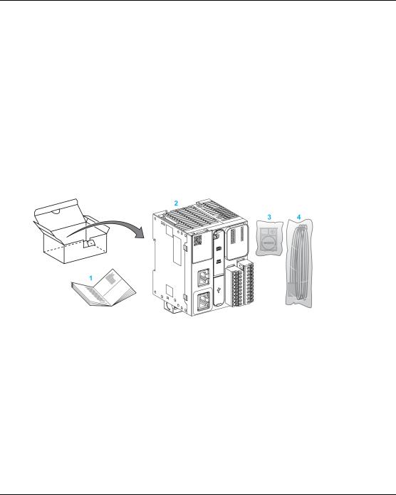
Delivery Content
The following figure presents the content of the delivery for a TM221M Logic Controller:
1 TM221M Logic Controller Instruction Sheet
2TM221M Logic Controller
3 Battery holder with lithium carbon monofluoride battery, type Panasonic BR2032.
4Analog cable
EIO0000003313 02/2020 |
29 |
M221 General Overview
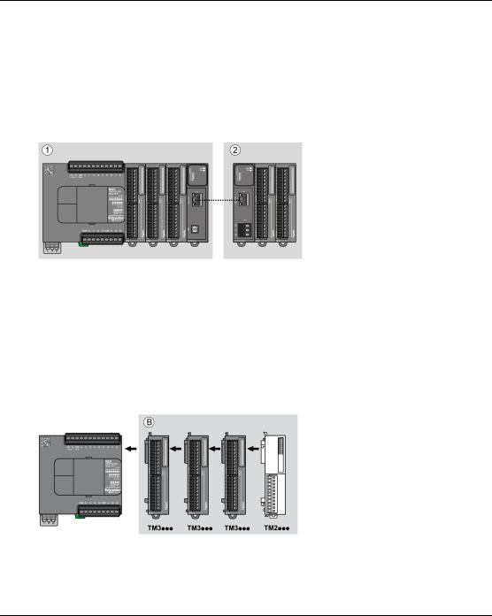
Maximum Hardware Configuration
Introduction
The M221 Logic Controller is a control system that offers an all-in-one solution with optimized configurations and an expandable architecture.
Local and Remote Configuration Principle
The following figure defines the local and remote configurations:
(1)Local configuration
(2)Remote configuration
M221 Logic Controller Local Configuration Architecture
Optimized local configuration and flexibility are provided by the association of:
M221 Logic Controller
TM3 expansion modules
TM2 expansion modules
Application requirements determine the architecture of your M221 Logic Controller configuration. The following figure represents the components of a local configuration:
(B) Expansion modules (see maximum number of modules)
30 |
EIO0000003313 02/2020 |
 Loading...