


Schneider Electric ION7650, ION7550 User Manual
PowerLogic® ION7550 / ION7650
Energy & Power Quality Meter
Installation Guide
December 2007

Danger
DANGER
CAUTION
PowerLogic ION7550 / ION7650 Installation Guide
This symbol indicates the presence of dangerous voltage within and outside the product enclosure
that may constitute a risk of electric shock, serious injury or death to persons if proper precautions
are not followed.
Caution
This symbol alerts the user to the presence of hazards that may cause minor or moderate injury to
persons, damage to property or damage to the device itself, if proper precautions are not followed.
Note
This symbol directs the user’s attention to important installation, operating and maintenance
instructions.
Installation Considerations
Installation and maintenance of the PowerLogic ION7550 / ION7650 meter should only be performed by qualified,
competent personnel that have appropriate training and experience with high voltage and current devices. The meter
must be installed in accordance with all local and national electrical codes.
Failure to observe the following instructions may result in severe injury or death.
During normal operation of the ION7550 / ION7650 meter, hazardous voltages are present on its termi-
nal strips, and throughout the connected potential transformer (PT), current transformer (CT), digital (status) input, control power and external I/O circuits. PT and CT secondary circuits are capable of generating
lethal voltages and currents with their primary circuit energized. Follow standard safety precautions while
performing any installation or service work (i.e. removing PT fuses, shorting CT secondaries, etc.).
The terminal strips on the meter base should not be user-accessible after installation.
Do not use digital output devices for primary protection functions. These include applications where the
devices perform energy limiting functions or provide protection of people from injury. Do not use the
ION7550 / ION7650 in situations where failure of the devices can cause injury or death, or cause suffi-
cient energy to be released that can start a fire. The meter can be used for secondary protection functions.
Do not HIPOT/Dielectric test the digital (status) inputs, digital outputs, or communications terminals. Refer
to the label on the ION7550 / ION7650 meter for the maximum voltage level the device can
withstand.
Observe the following instructions, or permanent damage to the meter may occur.
The ION7550 / ION7650 meter offers a range of hardware options that affect input ratings. The
ION7550 / ION7650 meter’s serial number label lists all equipped options. Applying current levels incom-
patible with the current inputs will permanently damage the meter. This document provides installation
instructions applicable to each hardware option.
The ION7550 / ION7650 meter’s chassis ground must be properly connected to the switchgear earth
ground for the noise and surge protection circuitry to function correctly. Failure to do so will void the
warranty.
Terminal screw torque: Barrier-type (current, voltage, and relay terminal screws: 1.35 Nm (1.00 ft-lbf)
max. Captured-wire type (
digital inputs/outputs, communications, power supply: 0.90 Nm
(0.66 ft.lbf) max.
FCC Notice
This equipment has been tested and found to comply with the limits for a Class A digital device, pursuant to Part 15
of the FCC Rules. These limits are designed to provide reasonable protection against harmful interference when the
equipment is operated in a commercial environment.
© 2007 Schneider Electric. All rights reserved. 3

PowerLogic ION7550 / ION7650 Installation Guide
This equipment generates, uses, and can radiate radio frequency e nerg y and , i f n ot installed and used in accordance
with the instruction manual, may cause harmful interference to radio communications. Operation of this equipment
in a residential area is likely to cause harmful interference in which case the user will be required to correct the
interference at his own expense.
The Ringer Equivalence Number (REN) for the ION7550 / ION7650 optional internal modem is 0.6. Connection to
the ION7550 / ION7650 internal modem should be made via an FCC Part 68 compliant telephone cord (not
supplied). The ION7550 / ION7650 cannot be used on a public coin phone service or party line services.
Network Compatibility Notice for the Internal Modem
The internal modem in meters equipped with this option is compatible with the telephone systems of most countries
in the world. Use in some countries may require modification of the internal modem’s initialization strings. If problems
using the modem on your phone system occur, please contact Schneider Electric Technical Support.
Standards Compliance
CSA: Certified to CAN/
CSA C22.2 No.1010-1
Made by Power Measurement Ltd.
PowerLogic, ION, ION Enterprise, MeterM@il, WebMeter and Modbus are either trademarks or registered
trademarks of Schneider Electric.
Covered by one or more of the following patents:
U.S. Patent No's 7010438, 7006934, 6990395, 6988182, 6988025, 6983211, 6961641, 6957158,
6944555, 6871150, 6853978, 6825776, 6813571, 6798191, 6798190, 6792364, 6792337, 6751562,
6745138, 6737855, 6694270, 6687627, 6671654, 6671635, 6615147, 6611922, 6611773, 6563697,
6493644, 6397155, 6236949, 6186842, 6185508, 6000034, 5995911, 5828576, 5736847, 5650936,
D505087, D459259, D458863, D443541, D439535, D435471, D432934, D429655, D427533.
Certified to
UL 3111
4 © 2007 Schneider Electric. All rights reserved.
PowerLogic ION7550 / ION7650 Installation Guide
PowerLogic ION7550 / ION7650 Models
Integrated Display Model
Comes with front optical port.
TRAN (transducer) Model
The TRAN model has no display.
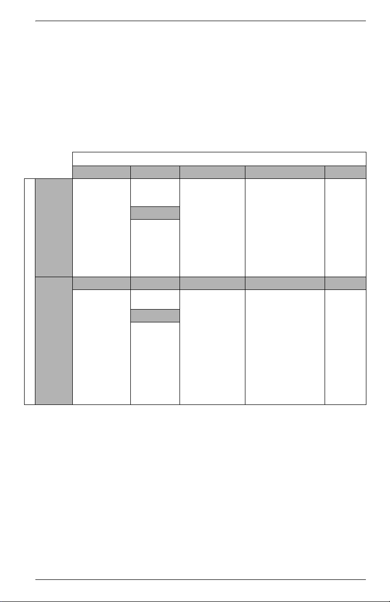
Available Options
Option
Form Factor Current Inputs COM I/O Security
ION7550
Model
ION7650
Integ. Display
TRAN
5 MB memory
10 MB memory
Up to 256
sampling rate
Form Factor Current Inputs COM I/O Security
Integ. Display
TRAN
5 MB memory
10 MB memory
Up to 512
sampling rate
(standard)
1024 sampling
rate (optional)
EN50160
compliance
IEC61000-4-30
Class A
compliance
Standard
(5 Amp)
1 Amp
Power Supply
Standard
Low Voltage
DC
Same as
ION7550
Power Supply
Same as
ION7550
Standard (RS-232,
RS-485, optical)
Ethernet RJ45
Ethernet Fiber
Modem
Same as
ION7550
Standard (8 digital
inputs, 3 Form C relays,
4 Form A outputs)
Extra 8 digital inputs
Four 0-1mA analog
inputs
Four 0-20 mA analog
inputs
Four -1 to 1mA analog
outputs
Four 0-20 mA analog
outputs
Same as ION7550 Same as
Standard
RMANSI
ION7550
1
2
Notes
1
Standard = password protected, no locking or sealing.
2
RMANSI = ANSI C12.16 approved revenue meter; meets ANSI C12.20
class 0.2 accuracy standards.
© 2007 Schneider Electric. All rights reserved. 5

PowerLogic ION7550 / ION7650 Installation Guide
DANGER
Navigation
Buttons
PROG/SELECT
Button
Softkeys
ESC Button
Communications
Card
Form C
Digital Outputs
Digital
Inputs
Form A
Digital Outputs
Digital Inputs Analog Inputs Analog Outputs
Voltage and Current Inputs
Power
Supply
Ground
Te rm i n al
Meter Front
Meter Back
Optical Port
I/O Expansion
Card
Operational
LEDs
ESC
PROG
Before You Begin
Before installing the meter, familiarize yourself with the steps in this guide and
read the safety precautions presented on the “Installation Considerations”
page.
Do not power up the meter until the current and voltage wiring is completed.
Recommended Tools
Phillips screwdriver
Precision flat-head screwdriver
Wire cutters / stripper
Meter Overview
Front Panel Button Functions
PROG/SELECT: Press the PROG/SELECT (program or select) button to enter Setup
mode. In Setup mode, press the
ESC: Press the ESC (Escape) button to return to a higher menu or discontinue a
configuration change.
NAVIGATION: Press the UP / DOWN arrow buttons to highlight menu items, or
increment / decrement numbers.
Press the
SOFTKEY: Press a SOFTKEY button to select the parameter that you want to
LEFT or RIGHT arrow buttons to move to an adjacent digit.
configure from the sub-menus.
6 © 2007 Schneider Electric. All rights reserved.
PROG/SELECT button to accept changes.
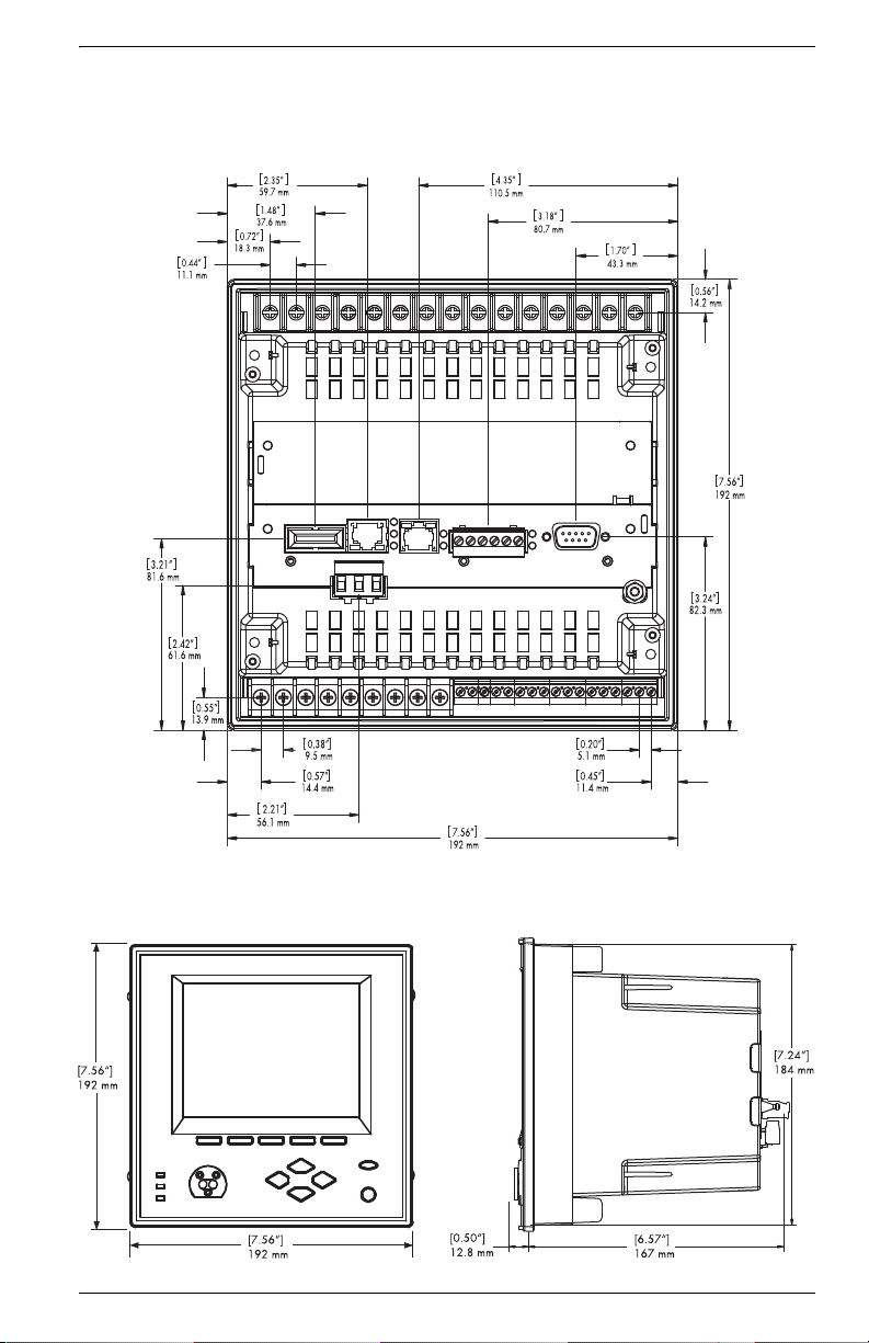
Unit Dimensions
Basic Model — Rear View
Basic Model — Front View
Basic Model — Side View
PowerLogic ION7550 / ION7650 Installation Guide
© 2007 Schneider Electric. All rights reserved. 7
PowerLogic ION7550 / ION7650 Installation Guide
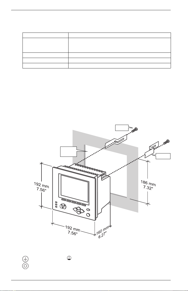
Screw
Bracket
DIN 192
Cutout
Step 1: Mount the Meter
Environmental Specifications
Mounting Location Indoor use
-20 to +70ºC (-4 to +158ºF) Standard Power Supply
Operating Range
Display Operating Range -20 to +70ºC (-4 to +158ºF)
Storage Range -40 to +85ºC (-40 to +185ºF)
Relative Humidity Range 5 to 95% non-condensing
Meter Battery Considerations
The meter’s battery life expectancy depends on both temperature and the
amount of time the meter is without power. For typical installations, the
battery should last 20 years or more. If the meter is not powered, the battery
will last a minimum of 7 years at room temperature.
Integrated Display Model
1. Fit the meter into the DIN standard 192 cutout (186 mm by 186 mm).
2. Slide the four brackets into their slots on the back of the meter and secure
using the four Phillips head screws. Do not overtighten.
-20 to +50ºC (-4 to +122ºF) Low Voltage DC Power Supply
No formation of ice
Step 2: Wire the Ground Terminal
Connect the terminal to a good earth ground with a 2.1 mm2 (14 AWG)
wire. Ensure that the terminal nut is tightened down securely onto the ground
wire. Do not use metal door hinges as a grounding point.
8 © 2007 Schneider Electric. All rights reserved.

PowerLogic ION7550 / ION7650 Installation Guide
R11R
12
R
13
R
21
R12
R11
R13
Internal Form C
Mechanical
Relay
External Supply
Alarm Lamp
NCNO
Load
Meter
K
Mechanical
relays should
always be
protected by
external fuses
DIGITAL OUTPUTS
D3
-
+
D2
-
+
D4
-
+
D1
-
+
1.8 Wh
+
_
D1
Internal Form A
Solid State Relay
+
+
_
D3
_
D2
+
_ _
+
_
+
_
+
_
D1
+
D4 output is factory-configured to pulse once every 1.8 Wh for Class 20 meters,
or once every 0.18 Wh for Class 2 meters (for calibration testing purposes).
Meter
External
Relays
External Supply
30VDC max
Step 3: Wire the Digital I/O and Analog I/O
Form C Digital Outputs: Mechanical Relays R1 - R3
Type Form C (R1, R2, R3)
Contacts K (common), Y (NO), Z (NC)
Wire Use wiring that is appropriate for the application
Connector Ring or split ring connector
Voltage Rating 250 VAC / 30 VDC
Rated Load @
Rated Voltage
Max. Voltage 380 VAC / 125 VDC between K and NO/NC
MOV Protection 300 V max. between NO and NC
Max. Load @
Max. Voltage
Turn-On Time 15 ms max.
Isolation 5,000 VAC for 60 s
Turn-Off Time 5 ms max.
Lifetime
Update time ½ cycle or 1 s
Resistive: 10 A (AC/DC)
Inductive (PF=0.4): 7.5 A (AC) / 5 A (DC)
3 A (AC) / 0.2 A (DC)
No load = 10,000,000 operations
Rated voltage and load = 100,000 operations
Form A Digital Outputs: Solid State Relays D1 - D4
Typ e Fo r m A (D1, D2, D3, D4)
Wire
1.3 to 0.1 mm
2
(16 to 28 AWG)
Signal Type Continuous or pulse
Max. Load Voltage 30 VDC
Max. Load Current 80 mA per channel
Isolation
Optically isolated; max. 5,000 V RMS isolation
(UL-E91231)
Scan Time ½ cycle or 1 s
© 2007 Schneider Electric. All rights reserved. 9
 Loading...