


Schneider Electric KVM1116R User Manual
User Guide
KVM Switch
KVM1116R
990-5925-001
Publication Date: 12/2017

APC by Schneider Electric Legal Disclaimer
The information presented in this manual is not warranted by APC by Schneider Electric to be authoritative,
error free, or complete. This publication is not meant to be a substitute for a detailed operational and site
specific development plan. Therefore, APC by Schneider Electric assumes no liability for damages, violations of
codes, improper installation, system failures, or any other problems that could arise based on the use of this
Publication.
The information contained in this Publication is provided as is and has been prepared solely for the purpose of
evaluating data center design and construction. This Publication has been compiled in good faith by APC by
Schneider Electric. However, no representation is made or warranty given, either express or implied, as to the
completeness or accuracy of the information this Publication contains.
IN NO EVENT SHALL APC BY SCHNEIDER ELECTRIC, OR ANY PARENT, AFFILIATE OR SUBSIDIARY
COMPANY OF APC BY SCHNEIDER ELECTRIC OR THEIR RESPECTIVE OFFICERS, DIRECTORS, OR
EMPLOYEES BE LIABLE FOR ANY DIRECT, INDIRECT, CONSEQUENTIAL, PUNITIVE, SPECIAL, OR
INCIDENTAL DAMAGES (INCLUDING, WITHOUT LIMITATION, DAMAGES FOR LOSS OF BUSINESS,
CONTRACT, REVENUE, DATA, INFORMATION, OR BUSINESS INTERRUPTION) RESULTING FROM,
ARISING OUT, OR IN CONNECTION WITH THE USE OF, OR INABILITY TO USE THIS PUBLICATION OR
THE CONTENT, EVEN IF APC BY SCHNEIDER ELECTRIC HAS BEEN EXPRESSLY ADVISED OF THE
POSSIBILITY OF SUCH DAMAGES. APC BY SCHNEIDER ELECTRIC RESERVES THE RIGHT TO MAKE
CHANGES OR UPDATES WITH RESPECT TO OR IN THE CONTENT OF THE PUBLICATION OR THE
FORMAT THEREOF AT ANY TIME WITHOUT NOTICE.
Copyright, intellectual, and all other proprietary rights in the content (including but not limited to software, audio,
video, text, and photographs) rests with APC by Schneider Electric or its licensors. All rights in the content not
expressly granted herein are reserved. No rights of any kind are licensed or assigned or shall otherwise pass to
persons accessing this information.
This Publication shall not be for resale in whole or in part.

Contents
General Information................................................................................... 1
Safety . . . . . . . . . . . . . . . . . . . . . . . . . . . . . . . . . . . . . . . . . . . . . . . . . . . . . . . .2
Safety map . . . . . . . . . . . . . . . . . . . . . . . . . . . . . . . . . . . . . . . . . . . . . . 2
Material Declaration of BSMI . . . . . . . . . . . . . . . . . . . . . . . . . . . . . . . 3
Caution/Warning . . . . . . . . . . . . . . . . . . . . . . . . . . . . . . . . . . . . . . . . . 3
Safety instructions . . . . . . . . . . . . . . . . . . . . . . . . . . . . . . . . . . . . . . . 4
Taking Delivery. . . . . . . . . . . . . . . . . . . . . . . . . . . . . . . . . . . . . . . . . . . . . . . . .6
Inventory . . . . . . . . . . . . . . . . . . . . . . . . . . . . . . . . . . . . . . . . . . . . . . . 6
System Requirements . . . . . . . . . . . . . . . . . . . . . . . . . . . . . . . . . . . . . . . . . . .6
Remote User Computers . . . . . . . . . . . . . . . . . . . . . . . . . . . . . . . . . . 6
Servers . . . . . . . . . . . . . . . . . . . . . . . . . . . . . . . . . . . . . . . . . . . . . . . . . 6
Video . . . . . . . . . . . . . . . . . . . . . . . . . . . . . . . . . . . . . . . . . . . . . . . . . . 7
KVM Server Modules and cables . . . . . . . . . . . . . . . . . . . . . . . . . . . 7
Supported Operating Systems . . . . . . . . . . . . . . . . . . . . . . . . . . . . . 7
Browsers . . . . . . . . . . . . . . . . . . . . . . . . . . . . . . . . . . . . . . . . . . . . . . . 7
Max Server connections . . . . . . . . . . . . . . . . . . . . . . . . . . . . . . . . . . 7
Components . . . . . . . . . . . . . . . . . . . . . . . . . . . . . . . . . . . . . . . . . . . . . . . . . . .8
Front . . . . . . . . . . . . . . . . . . . . . . . . . . . . . . . . . . . . . . . . . . . . . . . . . . . 8
Rear . . . . . . . . . . . . . . . . . . . . . . . . . . . . . . . . . . . . . . . . . . . . . . . . . . . 8
Installation .................................................................................................. 9
Rack Mounting . . . . . . . . . . . . . . . . . . . . . . . . . . . . . . . . . . . . . . . . . . . . . . . . .9
Rack Mounting - Front . . . . . . . . . . . . . . . . . . . . . . . . . . . . . . . . . . . . 9
Rack Mounting - Rear . . . . . . . . . . . . . . . . . . . . . . . . . . . . . . . . . . . 10
Single Level Installation . . . . . . . . . . . . . . . . . . . . . . . . . . . . . . . . . . . . . . . .11
Single Level Installation Diagram . . . . . . . . . . . . . . . . . . . . . . . . . 11
Tiering Multiple KVM Switches. . . . . . . . . . . . . . . . . . . . . . . . . . . . . . . . . . .12
Two Level Installation . . . . . . . . . . . . . . . . . . . . . . . . . . . . . . . . . . . 12
Two Level Installation Diagram . . . . . . . . . . . . . . . . . . . . . . . . . . . . 12
Supported KVM Switches . . . . . . . . . . . . . . . . . . . . . . . . . . . . . . . . . . . . . . .13
Hardware Setup . . . . . . . . . . . . . . . . . . . . . . . . . . . . . . . . . . . . . . . . . . . . . . .13
Cable considerations . . . . . . . . . . . . . . . . . . . . . . . . . . . . . . . . . . . . 13
Hot plugging . . . . . . . . . . . . . . . . . . . . . . . . . . . . . . . . . . . . . . . . . . . 13
The Adapter ID function . . . . . . . . . . . . . . . . . . . . . . . . . . . . . . . . . 13
Removing power and restarting . . . . . . . . . . . . . . . . . . . . . . . . . . . 13
Port ID numbering . . . . . . . . . . . . . . . . . . . . . . . . . . . . . . . . . . . . . . 14
Port selection . . . . . . . . . . . . . . . . . . . . . . . . . . . . . . . . . . . . . . . . . . 14
Removing and Replacing the KVM Switch ............................................ 15
Super Administrator Setup ..................................................................... 16
First Time Setup. . . . . . . . . . . . . . . . . . . . . . . . . . . . . . . . . . . . . . . . . . . . . . .16
Network Setup . . . . . . . . . . . . . . . . . . . . . . . . . . . . . . . . . . . . . . . . . . . . . . . .16
Changing the Super Administrator Login . . . . . . . . . . . . . . . . . . . . . . . . . .16
KVM1116R User Guide ii

Logging In................................................................................................. 18
Local Console Login . . . . . . . . . . . . . . . . . . . . . . . . . . . . . . . . . . . . . . . . . . .18
Browser Login . . . . . . . . . . . . . . . . . . . . . . . . . . . . . . . . . . . . . . . . . . . . . . . .18
Windows Client AP Login . . . . . . . . . . . . . . . . . . . . . . . . . . . . . . . . . . . . . . .19
Connect using Windows Client AP . . . . . . . . . . . . . . . . . . . . . . . . . 19
The File Menu . . . . . . . . . . . . . . . . . . . . . . . . . . . . . . . . . . . . . . . . . . . 19
Java Client AP Login . . . . . . . . . . . . . . . . . . . . . . . . . . . . . . . . . . . . . . . . . . .20
Connect using Java Client AP . . . . . . . . . . . . . . . . . . . . . . . . . . . . . 20
The User Interface.................................................................................... 21
The Web Browser Main Page . . . . . . . . . . . . . . . . . . . . . . . . . . . . . . . . . . . .21
The Tab Bar . . . . . . . . . . . . . . . . . . . . . . . . . . . . . . . . . . . . . . . . . . . . 22
The AP GUI Main Page . . . . . . . . . . . . . . . . . . . . . . . . . . . . . . . . . . . . . . . . .23
The Local Console GUI Main Page. . . . . . . . . . . . . . . . . . . . . . . . . . . . . . . .23
The Control Panel . . . . . . . . . . . . . . . . . . . . . . . . . . . . . . . . . . . . . . . . . . . . .24
WinClient Control Panel Functions . . . . . . . . . . . . . . . . . . . . . . . . . 26
Macros . . . . . . . . . . . . . . . . . . . . . . . . . . . . . . . . . . . . . . . . . . . . . . . . 27
Video Settings . . . . . . . . . . . . . . . . . . . . . . . . . . . . . . . . . . . . . . . . . . 30
The Message Board . . . . . . . . . . . . . . . . . . . . . . . . . . . . . . . . . . . . . 31
Virtual Media . . . . . . . . . . . . . . . . . . . . . . . . . . . . . . . . . . . . . . . . . . . 31
Zoom . . . . . . . . . . . . . . . . . . . . . . . . . . . . . . . . . . . . . . . . . . . . . . . . . 32
The On-Screen Keyboard . . . . . . . . . . . . . . . . . . . . . . . . . . . . . . . . 33
Mouse Pointer Type . . . . . . . . . . . . . . . . . . . . . . . . . . . . . . . . . . . . . 33
Mouse DynaSync Mode . . . . . . . . . . . . . . . . . . . . . . . . . . . . . . . . . . 34
Control Panel Configuration . . . . . . . . . . . . . . . . . . . . . . . . . . . . . . 35
The Java Control Panel . . . . . . . . . . . . . . . . . . . . . . . . . . . . . . . . . . . 35
Port Access ............................................................................................. 36
The Sidebar . . . . . . . . . . . . . . . . . . . . . . . . . . . . . . . . . . . . . . . . . . . . . . . . . .37
The Sidebar Tree Structure . . . . . . . . . . . . . . . . . . . . . . . . . . . . . . . 37
Sidebar Utilities . . . . . . . . . . . . . . . . . . . . . . . . . . . . . . . . . . . . . . . . 37
Port and Outlet Naming . . . . . . . . . . . . . . . . . . . . . . . . . . . . . . . . . . 38
Scan . . . . . . . . . . . . . . . . . . . . . . . . . . . . . . . . . . . . . . . . . . . . . . . . . . 39
Array . . . . . . . . . . . . . . . . . . . . . . . . . . . . . . . . . . . . . . . . . . . . . . . . . . 39
Filter . . . . . . . . . . . . . . . . . . . . . . . . . . . . . . . . . . . . . . . . . . . . . . . . . . 39
KVM Devices and Ports - Connections Page . . . . . . . . . . . . . . . . . . . . . . .39
Device Level . . . . . . . . . . . . . . . . . . . . . . . . . . . . . . . . . . . . . . . . . . . . 39
Port Level . . . . . . . . . . . . . . . . . . . . . . . . . . . . . . . . . . . . . . . . . . . . . . 40
History. . . . . . . . . . . . . . . . . . . . . . . . . . . . . . . . . . . . . . . . . . . . . . . . . . . . . . .41
Favorites . . . . . . . . . . . . . . . . . . . . . . . . . . . . . . . . . . . . . . . . . . . . . . . . . . . . .42
User Preferences . . . . . . . . . . . . . . . . . . . . . . . . . . . . . . . . . . . . . . . . . . . . . .43
Sessions . . . . . . . . . . . . . . . . . . . . . . . . . . . . . . . . . . . . . . . . . . . . . . . . . . . . .45
Access . . . . . . . . . . . . . . . . . . . . . . . . . . . . . . . . . . . . . . . . . . . . . . . . . . . . . .46
Device Level Browser GUI Interface . . . . . . . . . . . . . . . . . . . . . . . . 46
Port Level Browser GUI Interface . . . . . . . . . . . . . . . . . . . . . . . . . . 47
Device Level AP GUI Interface . . . . . . . . . . . . . . . . . . . . . . . . . . . . . 47
Port Level AP GUI Interface . . . . . . . . . . . . . . . . . . . . . . . . . . . . . . . 48
KVM1116R User Guideii

Port Configuration . . . . . . . . . . . . . . . . . . . . . . . . . . . . . . . . . . . . . . . . . . . . .48
Device Level . . . . . . . . . . . . . . . . . . . . . . . . . . . . . . . . . . . . . . . . . . . 48
Port Level . . . . . . . . . . . . . . . . . . . . . . . . . . . . . . . . . . . . . . . . . . . . . . . . . . . .48
Port Properties . . . . . . . . . . . . . . . . . . . . . . . . . . . . . . . . . . . . . . . . . 48
Associated Links . . . . . . . . . . . . . . . . . . . . . . . . . . . . . . . . . . . . . . . . . . . . . .49
User Management .................................................................................... 50
Users . . . . . . . . . . . . . . . . . . . . . . . . . . . . . . . . . . . . . . . . . . . . . . . . . . . . . . . .50
Adding Users . . . . . . . . . . . . . . . . . . . . . . . . . . . . . . . . . . . . . . . . . . 51
Modifying User Accounts . . . . . . . . . . . . . . . . . . . . . . . . . . . . . . . . 52
Deleting User Accounts . . . . . . . . . . . . . . . . . . . . . . . . . . . . . . . . . . 52
Groups . . . . . . . . . . . . . . . . . . . . . . . . . . . . . . . . . . . . . . . . . . . . . . . . . . . . . .52
Creating Groups . . . . . . . . . . . . . . . . . . . . . . . . . . . . . . . . . . . . . . . . 52
Modifying Groups . . . . . . . . . . . . . . . . . . . . . . . . . . . . . . . . . . . . . . . 53
Deleting Groups . . . . . . . . . . . . . . . . . . . . . . . . . . . . . . . . . . . . . . . . 53
Users and Groups . . . . . . . . . . . . . . . . . . . . . . . . . . . . . . . . . . . . . . . . . . . . .53
Assigning Users to a Group From the User's Notebook . . . . . . . 54
Removing Users From a Group in the User's Notebook . . . . . . . . 54
Assigning Users to a Group From the Group's Notebook . . . . . . 54
Removing Users From a Group From the Group's Notebook . . . 54
Device Assignment . . . . . . . . . . . . . . . . . . . . . . . . . . . . . . . . . . . . . . . . . . . .55
Assigning Device Permissions From the User's Notebook . . . . . 55
Assigning Device Permissions From the Groups' Notebook . . . . 57
Device Management ................................................................................ 58
Device Information. . . . . . . . . . . . . . . . . . . . . . . . . . . . . . . . . . . . . . . . . . . . .58
General . . . . . . . . . . . . . . . . . . . . . . . . . . . . . . . . . . . . . . . . . . . . . . . 58
Operating Mode . . . . . . . . . . . . . . . . . . . . . . . . . . . . . . . . . . . . . . . . 58
Network . . . . . . . . . . . . . . . . . . . . . . . . . . . . . . . . . . . . . . . . . . . . . . . 59
IPv4 Settings . . . . . . . . . . . . . . . . . . . . . . . . . . . . . . . . . . . . . . . . . . . 59
IPv6 Settings . . . . . . . . . . . . . . . . . . . . . . . . . . . . . . . . . . . . . . . . . . . 60
ANMS . . . . . . . . . . . . . . . . . . . . . . . . . . . . . . . . . . . . . . . . . . . . . . . . . 60
SNMP Agent . . . . . . . . . . . . . . . . . . . . . . . . . . . . . . . . . . . . . . . . . . . 61
Authentication . . . . . . . . . . . . . . . . . . . . . . . . . . . . . . . . . . . . . . . . . . 61
OOBC . . . . . . . . . . . . . . . . . . . . . . . . . . . . . . . . . . . . . . . . . . . . . . . . . 63
Security. . . . . . . . . . . . . . . . . . . . . . . . . . . . . . . . . . . . . . . . . . . . . . . . . . . . . .64
Login Failures . . . . . . . . . . . . . . . . . . . . . . . . . . . . . . . . . . . . . . . . . . 64
Filter . . . . . . . . . . . . . . . . . . . . . . . . . . . . . . . . . . . . . . . . . . . . . . . . . . 64
Account Policy . . . . . . . . . . . . . . . . . . . . . . . . . . . . . . . . . . . . . . . . . 65
Encryption . . . . . . . . . . . . . . . . . . . . . . . . . . . . . . . . . . . . . . . . . . . . . 65
Working Mode . . . . . . . . . . . . . . . . . . . . . . . . . . . . . . . . . . . . . . . . . . 66
Private Certificate . . . . . . . . . . . . . . . . . . . . . . . . . . . . . . . . . . . . . . . 66
Certificate Signing Request . . . . . . . . . . . . . . . . . . . . . . . . . . . . . . . 67
Date/Time . . . . . . . . . . . . . . . . . . . . . . . . . . . . . . . . . . . . . . . . . . . . . . 68
Port Operation.......................................................................................... 69
Connecting to a Port . . . . . . . . . . . . . . . . . . . . . . . . . . . . . . . . . . . . . . . . . . .69
KVM1116R User Guide iii

Port Toolbar . . . . . . . . . . . . . . . . . . . . . . . . . . . . . . . . . . . . . . . . . . . . . . . . . .69
Toolbar icons . . . . . . . . . . . . . . . . . . . . . . . . . . . . . . . . . . . . . . . . . . 70
Toolbar Hotkey Port Switching . . . . . . . . . . . . . . . . . . . . . . . . . . . . 70
Auto Scanning . . . . . . . . . . . . . . . . . . . . . . . . . . . . . . . . . . . . . . . . . 71
Skip Mode . . . . . . . . . . . . . . . . . . . . . . . . . . . . . . . . . . . . . . . . . . . . . 71
Recalling the Port Access Page . . . . . . . . . . . . . . . . . . . . . . . . . . . . . . . . . .71
GUI Hotkey Summary Table . . . . . . . . . . . . . . . . . . . . . . . . . . . . . . . . . . . . .71
Keyboard Emulation . . . . . . . . . . . . . . . . . . . . . . . . . . . . . . . . . . . . . . . . . . .72
Mac Keyboard . . . . . . . . . . . . . . . . . . . . . . . . . . . . . . . . . . . . . . . . . . 72
Sun Keyboard . . . . . . . . . . . . . . . . . . . . . . . . . . . . . . . . . . . . . . . . . . 73
Panel Array Mode . . . . . . . . . . . . . . . . . . . . . . . . . . . . . . . . . . . . . . . . . . . . .74
Panel Array Toolbar . . . . . . . . . . . . . . . . . . . . . . . . . . . . . . . . . . . . . 74
Multiuser Operation . . . . . . . . . . . . . . . . . . . . . . . . . . . . . . . . . . . . . . . . . . .75
Users and Buses . . . . . . . . . . . . . . . . . . . . . . . . . . . . . . . . . . . . . . . 75
Log ............................................................................................................ 76
Log Information . . . . . . . . . . . . . . . . . . . . . . . . . . . . . . . . . . . . . . . . . . . . . . .76
Log Notification Settings. . . . . . . . . . . . . . . . . . . . . . . . . . . . . . . . . . . . . . . .77
Maintenance ............................................................................................ 78
Main Firmware Upgrade . . . . . . . . . . . . . . . . . . . . . . . . . . . . . . . . . . . . . . . .78
Adapter Firmware Upgrade . . . . . . . . . . . . . . . . . . . . . . . . . . . . . . . . . . . . .79
Firmware Upgrade Recovery . . . . . . . . . . . . . . . . . . . . . . . . . . . . . . . . . . . .79
Adapter Firmware Upgrade Recovery . . . . . . . . . . . . . . . . . . . . . . . . . . . . .79
Backup/Restore . . . . . . . . . . . . . . . . . . . . . . . . . . . . . . . . . . . . . . . . . . . . . . .80
Backup . . . . . . . . . . . . . . . . . . . . . . . . . . . . . . . . . . . . . . . . . . . . . . . . 80
Restore . . . . . . . . . . . . . . . . . . . . . . . . . . . . . . . . . . . . . . . . . . . . . . . 80
System Operation . . . . . . . . . . . . . . . . . . . . . . . . . . . . . . . . . . . . . . . . . . . . .80
The Download Tab . . . . . . . . . . . . . . . . . . . . . . . . . . . . . . . . . . . . . . . . . . . . .81
The Log Server. . . . . . . . . . . . . . . . . . . . . . . . . . . . . . . . . . . . . . . . . . . . . . . .81
Installation . . . . . . . . . . . . . . . . . . . . . . . . . . . . . . . . . . . . . . . . . . . . . 81
Starting Up . . . . . . . . . . . . . . . . . . . . . . . . . . . . . . . . . . . . . . . . . . . . 81
The Menu Bar . . . . . . . . . . . . . . . . . . . . . . . . . . . . . . . . . . . . . . . . . . 82
The Log Server Main Screen . . . . . . . . . . . . . . . . . . . . . . . . . . . . . . 83
OpenLDAP . . . . . . . . . . . . . . . . . . . . . . . . . . . . . . . . . . . . . . . . . . . . . 84
Factory Default Settings . . . . . . . . . . . . . . . . . . . . . . . . . . . . . . . . . . . . . . . .85
Serial Adapter Pin Assignments. . . . . . . . . . . . . . . . . . . . . . . . . . . . . . . . . .86
Virtual Media Support . . . . . . . . . . . . . . . . . . . . . . . . . . . . . . . . . . . . . . . . . .86
WinClient ActiveX Viewer / WinClient AP . . . . . . . . . . . . . . . . . . . . 86
Java Applet Viewer / Java Client AP . . . . . . . . . . . . . . . . . . . . . . . . 86
KVM1116R User Guideiv

IP Address Determination . . . . . . . . . . . . . . . . . . . . . . . . . . . . . . . . . . . . . . .87
Browser . . . . . . . . . . . . . . . . . . . . . . . . . . . . . . . . . . . . . . . . . . . . . . . 87
IPv6 . . . . . . . . . . . . . . . . . . . . . . . . . . . . . . . . . . . . . . . . . . . . . . . . . . 87
Port Forwarding . . . . . . . . . . . . . . . . . . . . . . . . . . . . . . . . . . . . . . . . 88
Connection Setup Example (Windows 7) . . . . . . . . . . . . . . . . . . . . 89
Additional Mouse Synchronization Procedures . . . . . . . . . . . . . . 89
KVM-SERIAL Server Module Configuration and Operation. . . . . . . . . . . .90
Configuration . . . . . . . . . . . . . . . . . . . . . . . . . . . . . . . . . . . . . . . . . . 90
Operation . . . . . . . . . . . . . . . . . . . . . . . . . . . . . . . . . . . . . . . . . . . . . . 90
Internal Serial Interface Configuration. . . . . . . . . . . . . . . . . . . . . . . . . . . . .90
Navigation . . . . . . . . . . . . . . . . . . . . . . . . . . . . . . . . . . . . . . . . . . . . . 90
Operation . . . . . . . . . . . . . . . . . . . . . . . . . . . . . . . . . . . . . . . . . . . . . . 91
Switch Level Configuration . . . . . . . . . . . . . . . . . . . . . . . . . . . . . . . 91
Port Level Configuration . . . . . . . . . . . . . . . . . . . . . . . . . . . . . . . . . 91
Troubleshooting....................................................................................... 92
General Operation . . . . . . . . . . . . . . . . . . . . . . . . . . . . . . . . . . . . . . 92
Mouse Problems . . . . . . . . . . . . . . . . . . . . . . . . . . . . . . . . . . . . . . . . 93
Virtual Media . . . . . . . . . . . . . . . . . . . . . . . . . . . . . . . . . . . . . . . . . . . 94
Web Browser . . . . . . . . . . . . . . . . . . . . . . . . . . . . . . . . . . . . . . . . . . . 94
The WinClient ActiveX Viewer and the WinClient AP . . . . . . . . . . 95
The Java Applet and Java Client AP . . . . . . . . . . . . . . . . . . . . . . . . 96
Sun Systems . . . . . . . . . . . . . . . . . . . . . . . . . . . . . . . . . . . . . . . . . . . 96
Mac Systems . . . . . . . . . . . . . . . . . . . . . . . . . . . . . . . . . . . . . . . . . . . 96
Redhat Systems . . . . . . . . . . . . . . . . . . . . . . . . . . . . . . . . . . . . . . . . 97
The Log Server . . . . . . . . . . . . . . . . . . . . . . . . . . . . . . . . . . . . . . . . . 97
Panel-Array Mode . . . . . . . . . . . . . . . . . . . . . . . . . . . . . . . . . . . . . . . 97
Specifications........................................................................................... 98
Two-Year Factory Warranty . . . . . . . . . . . . . . . . . . . . . . . . . . . . . . . . . . . . .99
Terms of warranty . . . . . . . . . . . . . . . . . . . . . . . . . . . . . . . . . . . . . . . 99
Non-transferable warranty . . . . . . . . . . . . . . . . . . . . . . . . . . . . . . . . 99
Exclusions . . . . . . . . . . . . . . . . . . . . . . . . . . . . . . . . . . . . . . . . . . . . . 99
Warranty claims . . . . . . . . . . . . . . . . . . . . . . . . . . . . . . . . . . . . . . . 100
KVM1116R User Guide v


General Information
NOTE: Save these instructions. Read and adhere to all the instructions. All servicing must be performed
by authorized personnel only.
The KVM switch allows local and remote users to monitor and access multiple servers from a single
console. The switch models differ by number of buses and KVM ports.
SKU Bus Support KVM Ports
KVM1116R 1 Local shared with 1Remote 16
• The switches use TCP/IP communications protocol. They can be accessed by their IP addresses
from anywhere on the LAN, WAN, or Internet. The location of the connecting computer is
irrelevent.
• Remote users log in using a browser or stand-alone Windows or Java GUI applications. Java
allows the switches to work with JRE (Java Runtime Environment) enabled operating systems,
ensuring multi-platform operability.
• The client software allows operators to exchange keyboard, video, and mouse signals with the
servers attached to the switches just as if they were working on the equipment directly.
• Up to 16 users can share the switch's buses. A Message Board feature allows them to
communicate with each other to facilitate port sharing.
• Administrators can perform maintenance tasks from installing and running GUI applications, to
BIOS level troubleshooting, routine monitoring, concurrent maintenance, and system
administration.
• Local console operation is accomplished by entering hotkey combinations from the keyboard with
a full screen GUI display.
• The Auto Scan feature permits automatic switching from port to port at user-specified intervals,
while the Panel Array Mode can display the video output of up to 42 servers at the same time.
• CAT 5e/6 cable links the switch to the servers. A 16 port switch can be installed in a 1U rack, and
can use the internal network wiring in most modern commercial buildings.
• The switch receives keyboard input directly. There is no software installation.
• Download firmware updates from www.apc.com.
• Adapter ID function stores port information like the adapter ID, OS, keyboard language, adapter
name, operation modes and more. When a KVM Adapter Cable is moved from one port to
another, the switch recognizes the adapter cable at the new location.
• Operate the entire installation from a single remote console located anywhere in the world.
• Virtual Media support.
1KVM1116R User Guide
Safety
Safety map
Read the instructions carefully to become familiar with the equipment before trying to install, operate,
service, or maintain it. The following special messages may appear throughout this manual or on the
equipment to warn of potential hazards or to call attention to information that clarifies or simplifies a
procedure.
The addition of this symbol to a Danger or Warning safety label indicates that an electrical
hazard exists which will result in personal injury if the instructions are not followed.
This is the safety alert symbol. It is used to alert you to potential personal injury hazards.
Obey all safety messages that follow this symbol to avoid possible injury or death.
DANGER
DANGER indicates an imminently hazardous situation which, if not avoided, will result in death
or serious injury.
WARNING
WARNING indicates a potentially hazardous situation which, if not avoided, can result in death
or serious injury.
CAUTION
CAUTION indicates a potentially hazardous situation which, if not avoided, can result in minor or
moderate injury.
NOTICE
NOTICE addresses practices not related to physical injury including certain environmental
hazards, potential damage or loss of data.
KVM1116R User Guide2
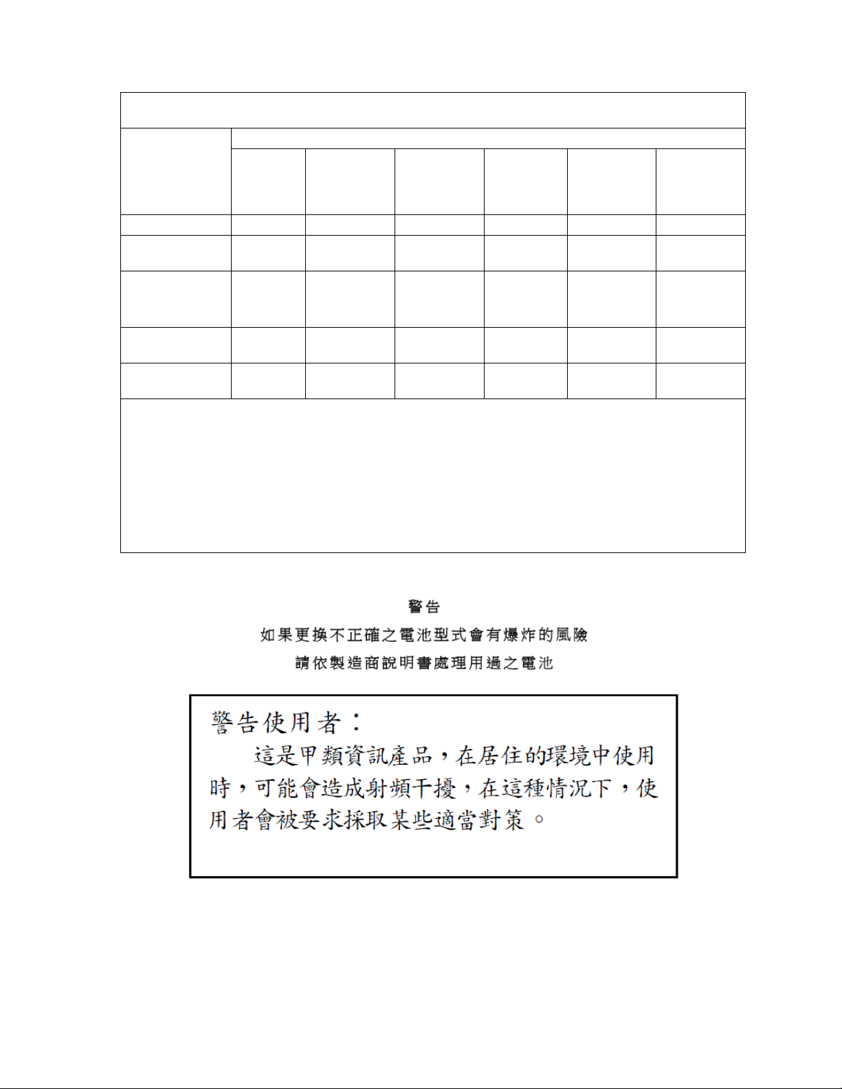
Material Declaration of BSMI
設備名稱:數位 KVM 切換器 16 埠,型號 (型式):KVM1116R
Device: Digital KVM switch 16 ports, model (type): KVM1116R
限用物質及其化學符號 Restricted substances
單元
Unit
電纜線 Cable
印刷電路部件
PCBA
電源模組
Switching Power
module
塑膠 / 其他部件
Plastic/Other parts
金屬部件
Metal parts
備考 1. 〝超出 0.1 wt % 〞及〝超出 0.01 wt % 〞係指限用物質之百分比含量超出百分比含量基準值。
Exceeds 0.1 wt%" and "Exceeds 0.01 wt%" means the percentage of the Restricted Substance exceeds
the percentage content basis.
備考 2. 〝○〞係指該項限用物質之百分比含量未超出百分比含量基準值。
The percentage content of the restricted substance does not exceed the percentage content of the
benchmark value.
備考 3. 〝-〞係指該項限用物質為排除項目。
The restricted substances are excluded items.
鉛
Lead (Pb)
OO O O O O
- OOOOO
OO - OO O
OO O O O O
汞
Mercury (Hg)
OOOOO
鎘
Cadmium(Cd)
六價鉻
Hexavalent
chromium
+6
)
(Cr
多溴聯苯
Polybrominated
biphenyls
(PBB)
多溴二苯醚
Polybrominated
diphenyl ethers
(PBDE)
Caution/Warning
3KVM1116R User Guide
Safety instructions
Read all of these instructions. Save them for future reference. Follow all warnings and instructions
marked on the device.
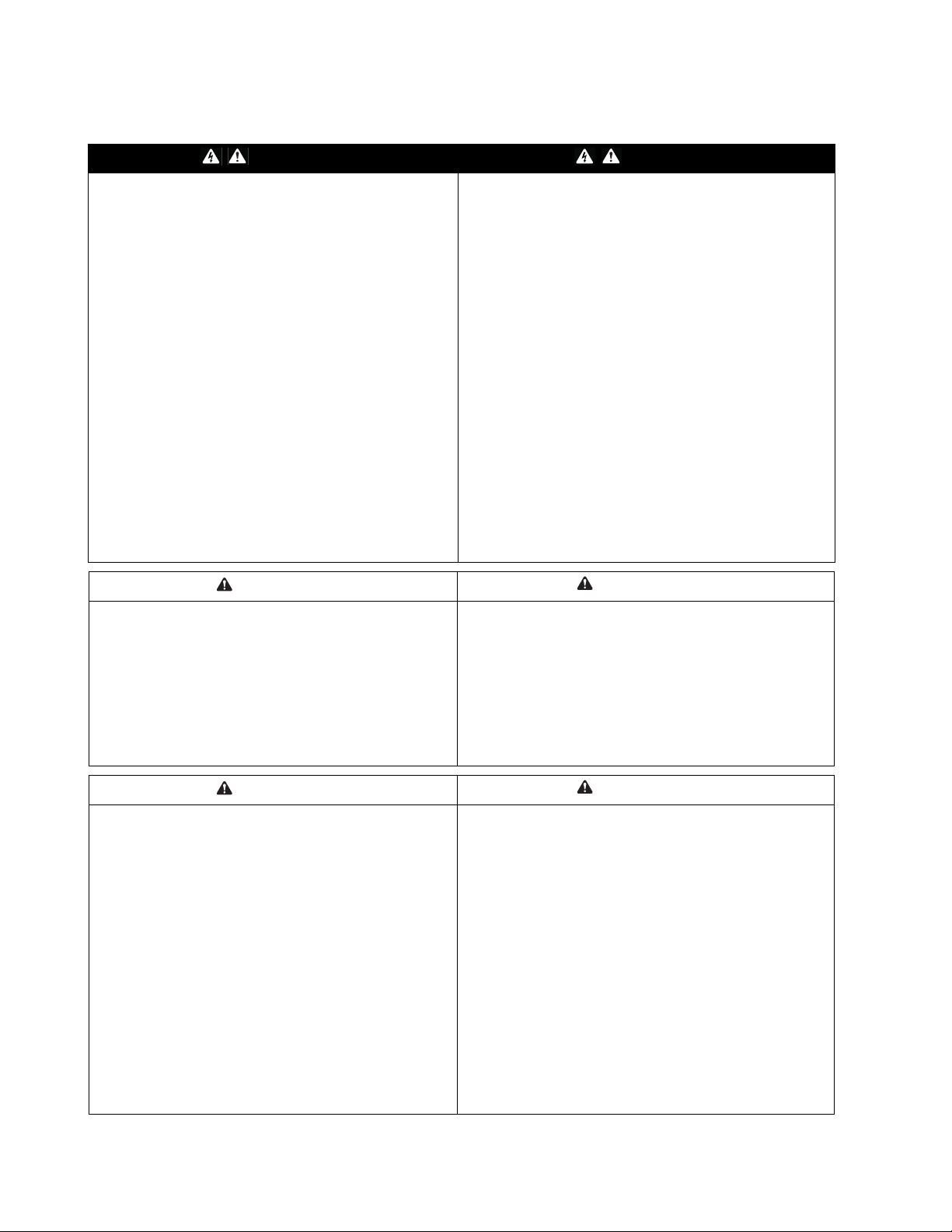
DANGER DANGER
HAZARD OF ELECTRIC SHOCK, EXPLOSION, OR ARC
FLASH
• Avoid circuit overload. Before energizing, review the
electrical specifications in the product documentation.
• Use only the supplied power cord or a power cord
approved for use in your region.
• The cord must have voltage and current ratings equal to
or greater than those of the product rating label
requirements.
• Plug the power cord into a grounded (earthed) outlet that
is easily accessible. Do not disable the grounding pin.
• Make sure that all equipment, including power strips, is
properly grounded.
• The AC inlet is the main disconnect device for the
product.
• This product has no user-serviceable parts inside. Do not
remove product cover. All repairs should be performed by
authorized personnel only.
Failure to follow these instructions can result in death
or serious injury.
RISQUE DE CHOC ÉLECTRIQUE, D'EXPLOSION OU
D'ÉCLAIR D'ARC ÉLECTRIQUE
• Évitez de surcharger le circuit. Avant de mettre le circuit
sous tension, vérifiez les caractéristiques électriques
indiquées dans la documentation du produit.
• Utilisez uniquement le cordon d’alimentation fourni ou un
cordon d’alimentation homologué dans votre région.
• Le cordon d'alimentation doit supporter une tension et un
courant égaux ou supérieurs aux exigences indiquées sur
l'étiquette des caractéristiques du produit.
• Reliez le cordon d'alimentation à une prise secteur avec
terre facilement accessible. Ne désactivez pas la broche
de terre.
• Assurez-vous que tout l'équipement est correctement relié
à la terre, y compris les rubans d'alimentation.
• La prise d'alimentation c.a. sert de déconnexion principale
du produit.
• Ce produit n'a aucun composant interne réparable par
l'utilisateur. Ne retirez pas le capot du produit. Toute
réparation doit être effectuée uniquement par du personnel
autorisé.
Le non-respect de ces instructions peut entraîner des
blessures graves, voire mortelles.
CAUTION ATTENTION
RISK OF EXPLOSION IF BATTERY IS REPLACED BY
AN INCORRECT BATTERY TYPE
• Ensure that batteries are replaced with the correct
battery type.
• Dispose of used batteries according to the instructions
included with the battery
Failure to follow these instructions can result in injury
or equipment damage.
CAUTION ATTENTION
HAZARD OF EQUIPMENT DAMAGE
• Do not connect the RJ-11 connector marked
"UPGRADE" to any telecommunication network.
• Plugging in devices other than those specified in the
product documentation may result in equipment damage
• Allow sufficient airflow for safe operation. To avoid
overheating, make sure the product enclosure openings
are never blocked or covered. Rack temperature must be
less than 40°C.
• Uneven mechanical loading can create a hazardous
condition.
• Do not use the product as a shelf.
• Use only the installation mounting hardware provided to
avoid damage.
Failure to follow these instructions can result in injury
or equipment damage.
RISQUE D’EXPLOSION SI LA BATTERIE EST
REMPLACÉE PAR UNE BATTERIE D’UN TYPE
INCORRECT
• Assurez-vous que les batteries de remplacement sont
du type correct.
• Mettez les batteries usagées au rebut conformément aux
instructions incluses avec la batterie.
Le non-respect de ces instructions risque de provoquer
des blessures ou d’endommager l’équipement.
RISQUE D'ENDOMMAGER L'ÉQUIPEMENT
• Ne raccordez le connecteur RJ-11 marqué « UPGRADE »
à aucun réseau de télécommunication.
• La connexion d'appareils autres que ceux indiqués dans la
documentation du produit peut entraîner des dommages à
l'équipement.
• Laissez une circulation d'air suffisante pour garantir un
fonctionnement en toute sécurité. Pour éviter une
surchauffe, assurez-vous que les ouvertures autour du
produit ne soient jamais obstruées ou recouvertes. La
température du rack doit être inférieure à 40 °C.
• Une charge mécanique inégale peut créer une situation
dangereuse.
• Le produit ne doit pas servir d'étagère.
• Utilisez uniquement la quincaillerie de fixation fournie pour
éviter d'endommager l'équipement.
Le non-respect de ces instructions peut entraîner des
blessures ou endommager l'équipement.
KVM1116R User Guide4

NOTICE
• Do not use the device near water, Never spill liquid of any kind on the device.
• Unplug the device from the wall outlet before cleaning. Do not use liquid or aerosol cleaners. Use a damp cloth for
cleaning.
• To help protect your system from sudden, transient increases and decreases in electrical power, use a surge
suppressor, line conditioner, or uninterruptible power supply (UPS).
• Before working on the rack, make sure that the stabilizers are secured to the rack, extended to the floor, and that the full
weight of the rack rests on the floor. Install front and side stabilizers on a single rack or front stabilizers for joined multiple
racks before working on the rack.
• Position system cables and power cables carefully; Be sure that nothing rests on any cables.
• Never push objects of any kind into or through cabinet slots. They may touch dangerous voltage points or short out parts
resulting in a risk of fire or electrical shock.
• Always load the rack from the bottom up, and load the heaviest item in the rack first.
• Make sure that the rack is level and stable before extending a device from the rack.
• Use caution when pressing the device rail release latches and sliding a device into or out of a rack; the slide rails can
pinch your fingers.
• After a device is inserted into the rack, carefully extend the rail into a locking position, and then slide the device into the
rack.
• Do not overload the AC supply branch circuit that provides power to the rack. The total rack load should not exceed 80
percent of the branch circuit rating.
• Make sure that all equipment used on the rack, including power strips and other electrical connectors, is properly
grounded.
• Ensure that proper airflow is provided to devices in the rack.
• Ensure that the operating ambient temperature of the rack environment does not exceed the maximum ambient
temperature specified for the equipment by the manufacturer
• Do not step on or stand on any device when servicing other devices in a rack.
• Equipment mounted on rails should not act as shelf or work surface.
• Route the power cord and cables so that they cannot be stepped on or tripped over.
AVIS
• Ne pas utiliser l'appareil près de l'eau, jamais de liquide d'aucune sorte sur l'appareil.
• Débranchez l'appareil de la prise murale avant de le nettoyer. Ne pas utiliser de nettoyants liquides ou en aérosol.
Utilisez un chiffon humide pour le nettoyage.
• Pour aider à protéger votre système contre les augmentations soudaines et transitoires et des diminutions de puissance
électrique, utilisez un limiteur de surtension, un conditionneur de ligne ou d'alimentation sans coupure (UPS).
• Avant de travailler sur le rack, assurez-vous que les stabilisateurs sont fixés au rack, étendu sur le sol, et que le poids
du rack repose sur le sol. Installez les stabilisateurs avant et latéraux d'un seul rack ou les stabilisateurs avant de
plusieurs racks joints avant de travailler sur le rack.
• Câbles du système de positionnement et de câbles électriques attentivement; Assurez-vous que rien ne repose sur les
câbles.
• Ne poussez jamais d'objets d'aucune sorte dans ou à travers les fentes du boîtier. Ils peuvent toucher des points de
tension dangereux ou court-circuiter résultant en un risque d'incendie ou de choc électrique.
• Chargez toujours le rack de bas en haut, et charger l'élément le plus lourd dans le rack en premier.
• Assurez-vous que le support est de niveau et stable avant d'étendre un dispositif de l'armoire.
• Faites preuve de prudence lorsque vous appuyez sur de dégagement des rails de dispositif verrous et glissant un
dispositif dans ou hors d'un rack; les glissières peuvent vous pincer les doigts.
• Après un dispositif est inséré dans le rack, étendez le rail avec précaution dans une position de verrouillage, puis faites
glisser l'appareil dans le rack.
• Ne surchargez pas le circuit de dérivation CA qui alimente le rack. La charge totale du rack ne doit pas dépasser 80
pour cent de la capacité du circuit de dérivation.
• Assurez-vous que tout le matériel utilisé sur le support, y compris les rampes d'alimentation et d'autres connecteurs
électriques, est correctement mis à la terre.
• Assurez-vous que la circulation d'air adéquate est fournie aux dispositifs du rack.
• S'assurer que la température ambiante de fonctionnement de l'environnement de l'armoire ne dépasse pas la
température ambiante maximale prévue pour l'équipement par le fabricant
• Ne pas marcher ou se tenir debout sur n'importe quel appareil lors de l'entretien d'autres appareils dans un rack.
• Le cordon d'alimentation et les câbles de sorte qu'ils ne peuvent pas être piétiné ou trébucher dessus.
• Les équipements montés sur rails/glissières ne doivent pas faire office d’étagère ou de surface de travail.
5KVM1116R User Guide

Taking Delivery
Examine the components at the time of delivery to be sure all parts are present and in good working
order. Anything missing or damaged must be reported immediately to the shipping firm and to APC.
Inventory
The package consists of:
• KVM Switch
• NEMA 5 - 15 power cord
• C13 - C14 power cord
• Rack Mount Bracket
• Serial Adapter (for modem connection)
• KVM Access Management Software USB key (please retain for future license upgrade)
• Literature Kit: Quick Start Guide, Safety Sheet, China ROHS and CD (containing KVM Access
Management software)
System Requirements
Remote User Computers
Remote user computers (also referred to as client computers) are computers logged into the switch from
remote locations over the internet.
These computers must have the following equipment installed:
• At least a PIII 1 GHz processor, with the screen resolution set to 1024 x 768.
• Browsers must support TLS 1.2 encryption.
• A network transfer speed of at least 512kbps.
• For the browser-based WinClient ActiveX Viewer, DirectX 8 must be present, and at least 150 MB
of memory must be available after installation.
• For the browser-based Java Applet Viewer the latest version of the Java Runtime Environment
(JRE) must be installed, and at least 205 MB of memory must be available after installation.
• For the Windows Client AP, DirectX 8 must be present, and at least 90 MB of memory must be
available after installation.
• For the Java Client AP, the latest version of the Java Runtime Environment (JRE) must be
installed, and at least 145 MB of memory must be available after installation.
• For the Log Server, you must have the Microsoft Jet OLEDB 4.0 or higher driver installed.
Servers
Servers are the computers connected to the switch by KVM Adapter Cables.
These servers must have the following equipment installed:
• A VGA, SVGA or multisync port
• For USB KVM Adapter Cable Connections: a Type A USB port and USB host controller
KVM1116R User Guide6
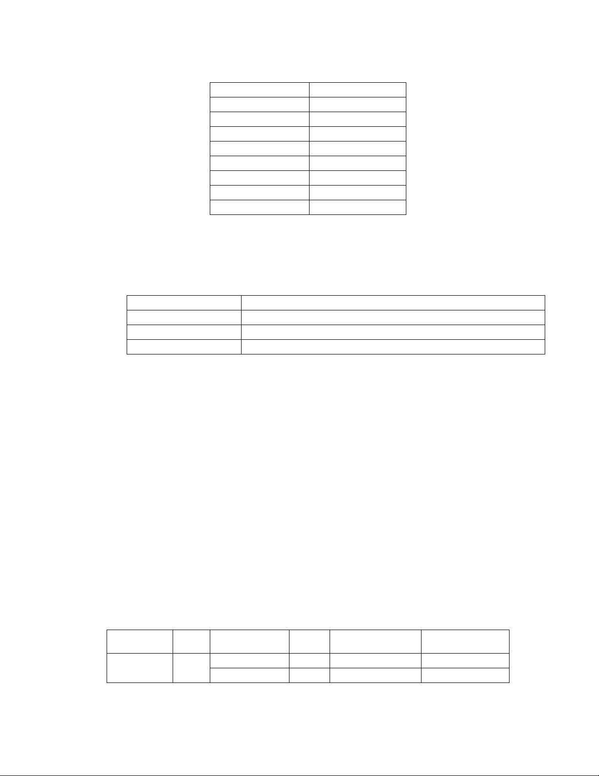
Video
Only the following non-interlaced video signals are supported:
Resolution Refresh Rates
640 x 480 60, 70, 72, 75, 85
720 x 400 70, 75
800 x 600 56, 60, 70, 72, 75, 85
1024 x 768 60, 70, 75, 85
1152 x 864 60, 70, 75, 85
1152 x 900 66, 76
1280 x 1024 60, 70, 75, 85,
1600 x 1200 60
KVM Server Modules and cables
NOTE: KVM server modules are also referred to as adapter cables in some dialog boxes.
• Cat5e (or higher) cable connects the switch to the KVM server modules.
• The following KVM server modules and cables are required for use with the switch.
Cable Type Port Type
KVM-USB Connect to devices with USB ports
KVM-USBVM Connect to devices with USB ports, virtual media support
KVM-SERIAL Connect to serial based devices
Supported Operating Systems
• Microsoft® Windows
• Linux
• UNIX
• Mac
®
®
®
®
Browsers
Supported browsers for remote users:
• Internet Explorer
• Chrome
®
®
• Firefox® for Windows or Linux
• Safari
• Opera
®
for Windows or Mac
®
• Mozilla® for Windows or Sun
• Netscape
®
Max Server connections
Parent
KVM Model Ports
KVM1116R 16 KVM0116A * 16 16 x 16 = 256 2
* Not covered in this manual. See the User Guides for these models for more information.
Child
Tiered KVM Ports
KVM0108A * 8 16 x 8 =128 2
®
Servers in a Single
Level Tier Maximum Levels
7KVM1116R User Guide
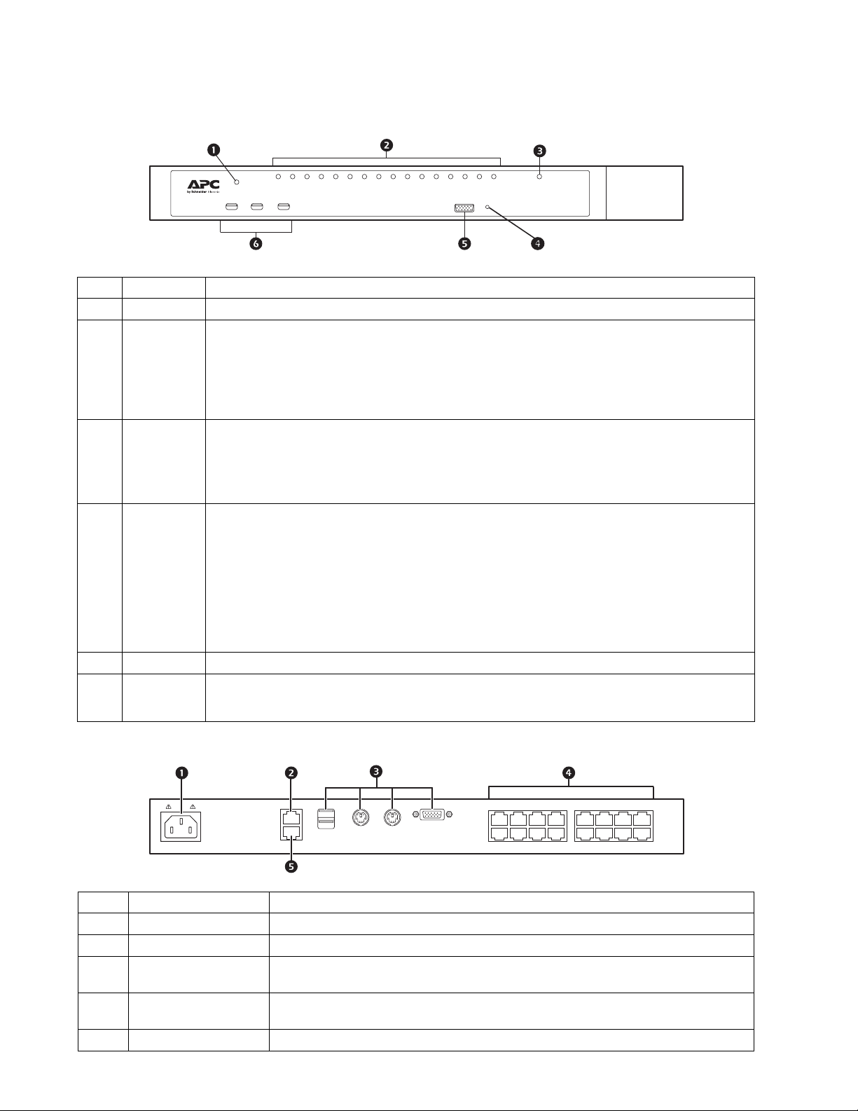
Components
aem0371c
Reset
Power
1 2 3 4 5 6 7 8 9 101112 13141516
Lan 1
KVM1116R
aem0370c
KVM1116R
Front
Item Name Description
Power LED Illuminated when the unit is powered up and ready to operate.
Port LEDs Provides status information about corresponding KVM Ports.
LAN LEDs Primary and Secondary 10/100/1000 Mbps LAN LEDs.
Reset Switch Use a small object like a paper clip or ballpoint pen to press the reset switch.
Console Port This port is not operational in the KVM1116R.
USB Ports
• GREEN: The computer attached to the port is On Line.
• RED: The computer attached to the port is Selected (has KVM focus).(Server is offline.)
• GREEN + RED (ORANGE): The computer attached to the port is On Line and Selected.
The LEDs are continuously ON under normal conditions. An LED flashes at half second intervals
when its corresponding port is accessed under Auto Scan Mode or Skip Mode.
• RED: 10 Mbps
• RED + GREEN (ORANGE): 100 Mbps
• GREEN: 1000 Mbps
Flashes to indicate that the switch is being accessed.
• To perform a system reset, press and release when the unit is running.
• To reset to the factory default settings, press and hold for +3 seconds when the unit is running.
NOTE: This does not clear User Account information. See “Factory Default Settings” on page 85,
for information on clearing user account information.
• To return to factory default firmware settings, rather than any upgraded version, press and hold
while powering on the unit. This allows recovery from a failed firmware upgrade so the upgrade
may be tried again.
NOTE: This operation is only performed after a firmware upgrade failure that results in the device
becoming inoperable.
• Connect USB storage peripherals (CD/DVD, HD, flash drives, etc.).
• A USB keyboard and mouse can be used in place of, or in addition to, a keyboard and mouse
plugged in on the rear panel.
Rear
Item Name Description
Power Socket 1 Plug power cable for Power Source 1 in here.
LAN Port(s) Connect the unit to the network interface (10/100/1000 Mbps) over the internet.
Local Console Port(s) Local console devices (keyboard, monitor and mouse), plug in here. Any combination
KVM Ports Cat 5e cables plug in to link the unit to the KVM Adapter Cables, which connect to the
Modem Port This port is not operational in the KVM1116R.
of USB, keyboards, and mice can be used.
servers.
KVM1116R User Guide8
Installation
KVM Adapter Cables connect the switch to the connected devices. A separate KVM Adapter Cable is
required for each server or device connection. See the list of KVM Adapter Cables on page 7.
NOTE: 1. Refer to the Safety section of this manual before installing the KVM switch.
2. Remove power from any device that will be connected to the installation. Unplug the power
cords of any computers that have the Keyboard Power On function.
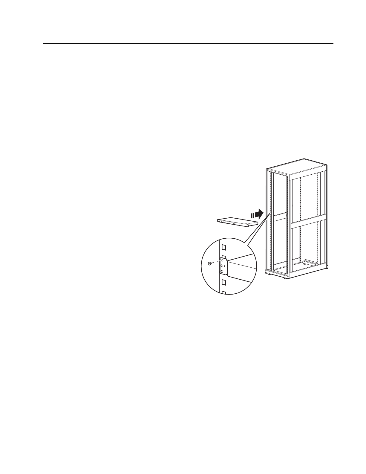
Rack Mounting
The switch can be mounted in a 19" (1U) rack. The mounting brackets can screw into either the front or
the back of the unit so that it can attach to the front or the back of the rack.
NOTE: Use cage nuts (not provided) for racks that are not pre-threaded.
Rack Mounting - Front
1. Position the switch in the front of the rack.
Align the mounting bracket holes with the
holes in the rack.
2. Secure the mounting brackets to the rack.
aem0372a
9KVM1116R User Guide
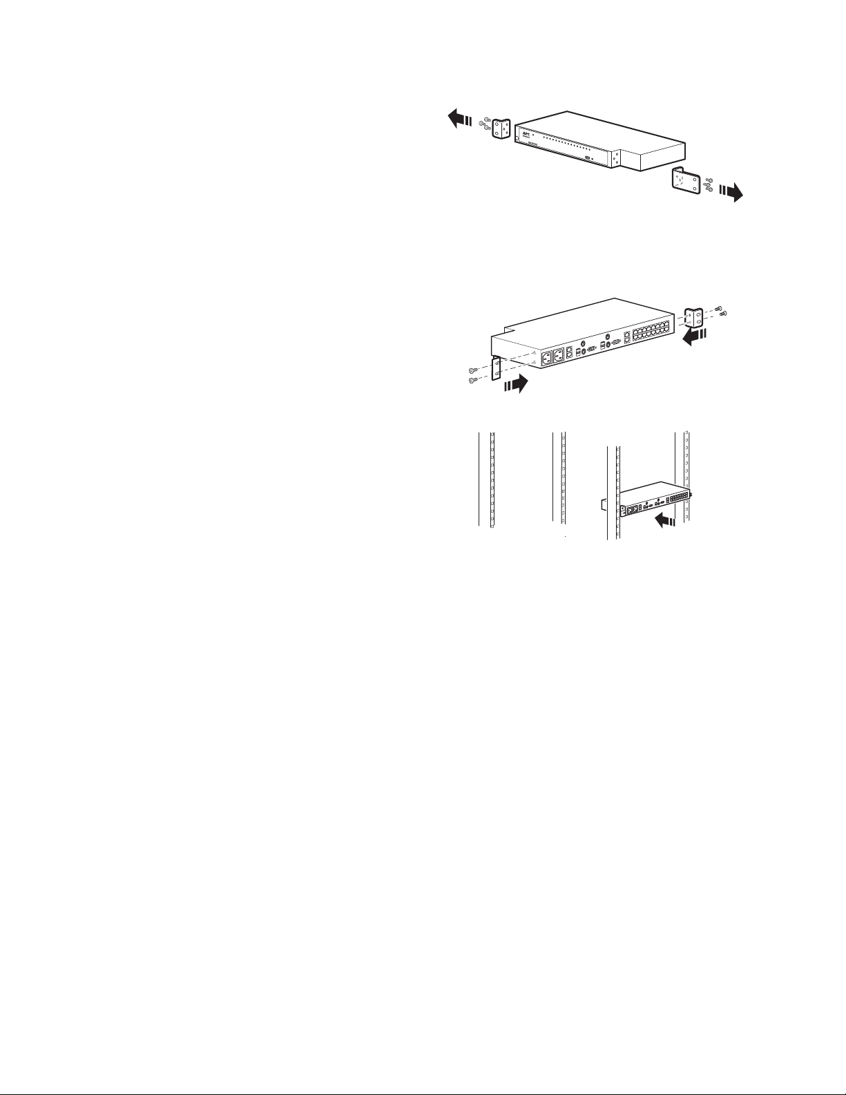
Rack Mounting - Rear
1. Remove the brackets from the front of the
KVM switch.
Remove the plug from the alignment hole.
2. Install the smaller bracket from the front of
the unit to the back. Install the rack mounting
bracket from the inventory to the rear of the
unit.
3. Slide the KVM switch into the rack. Align
the mounting bracket holes with the holes in
the rack.
4. Secure the mounting brackets to the rear of
the rack.
aem0449a
aem0450a
KVM1116R User Guide10
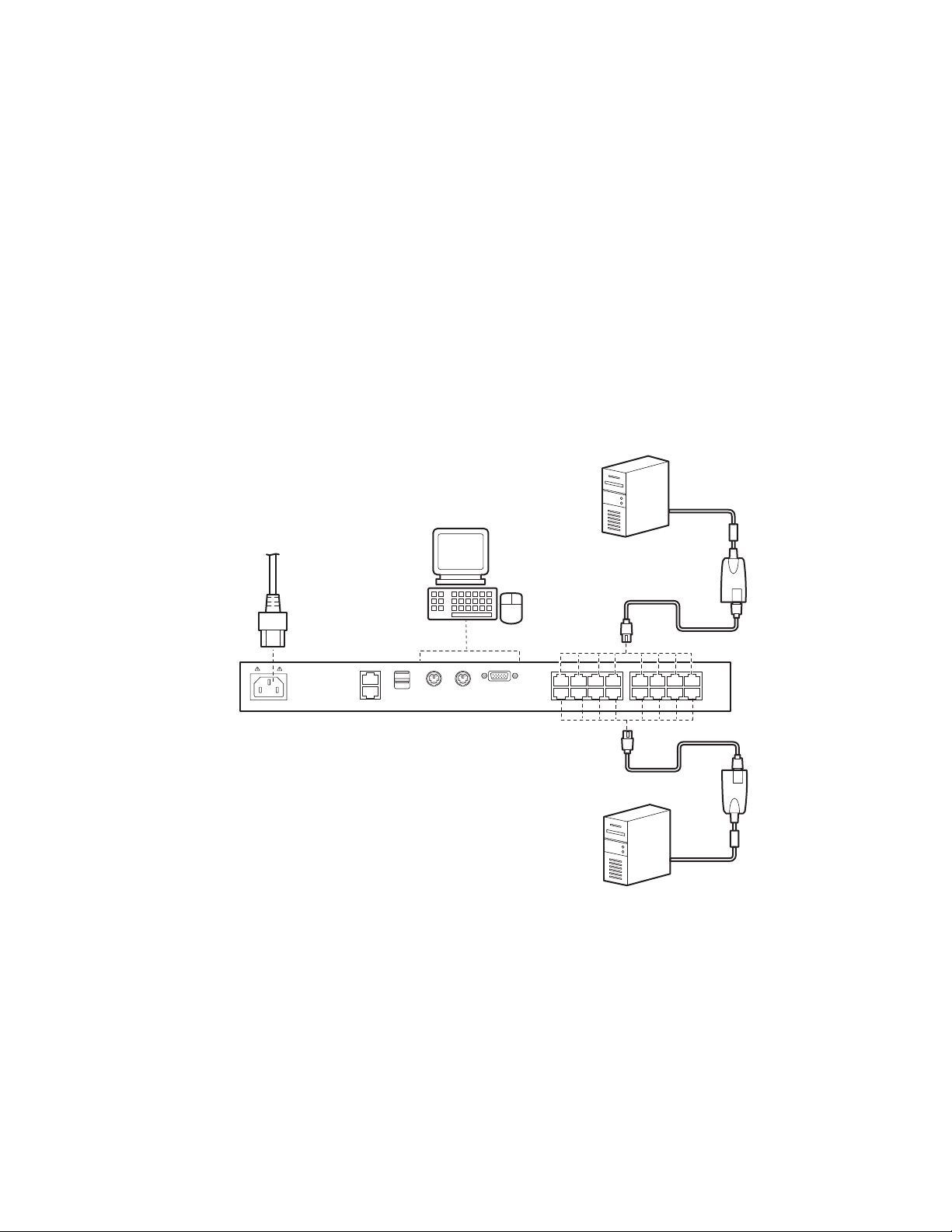
Single Level Installation
aem0448a
In a single level installation, no additional KVM switches are tiered from the original switch.
1. Plug the keyboard, monitor, and mouse of your Local Console into the Console Ports of the KVM
parent switch. Each port is color coded and marked with an appropriate icon.
NOTE: a. Any combination of keyboard and mouse connections can be used.
b. USB keyboards and mice can be plugged into the USB ports on the front panel or into
the console ports on the back.
2. Use Cat 5e cable to connect a KVM port to a KVM server module appropriate for the server being
installed.
3. Plug the connectors on the KVM server module into the appropriate server ports.
4. Plug a cable from the LAN or WAN into the KVM switch's primary network interface socket.
5. Plug the supplied power cord(s) into the switch's power socket(s), then into an AC power source.
6. Turn on the servers.
Single Level Installation Diagram
11KVM1116R User Guide
Tiering Multiple KVM Switches
haem0376b
KVM1116R
KVM0116A *
KVM-PS2
A tiered installation will greatly expand the number of servers that can be added to the installation.
Cascaded tiering adds capacity to a KVM installation, but the parent loses at least one KVM port for each
tiered KVM switch.
When the KVM consoles of the first-level KVM switch invoke the On Screen Display (OSD), all
computers on the tiered KVM installation are listed in the port directory. OSD is a screen for configuring
the KVM switch through the display.
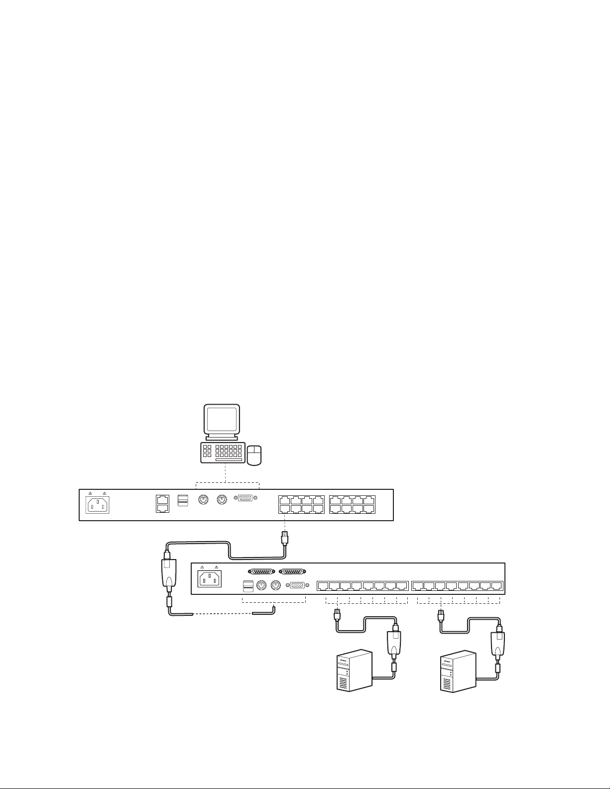
Two Level Installation
Up to 16 additional KVM switches can be tiered from the KVM ports of the original KVM switch. As many
as 256 servers can be controlled in a complete two level installation. In a tiered installation, the
KVM1116R switch is considered the First Level or Parent unit; the tiered switches (KVM0116A/
KVM0108A) are considered Second Level or Child units. Turn off power to all the devices, including all
pre-existing devices on the installation.
1. Use Cat 5e cable to connect any available KVM Port on the First Level unit (KVM1116R) to a
KVM-PS2 Adapter Cable.
2. Plug the adapter cable's KVM connectors to the Keyboard, Video, and Mouse Console ports of
the Second Level switch (KVM0116A / KVM0108A).
3. Connect any available KVM port on the Second Level unit to the Keyboard, Video, and Mouse
ports of the server.
4. Apply power to the First Level switch, then apply power to the Second Level switches.
5. Turn the servers on last.
Two Level Installation Diagram
* See the User Guide for KVM0116A and KVM0108A for more information about this KVM switch.
KVM1116R User Guide12

Supported KVM Switches
KVM switches that can be used in a tiered installation for KVM1116R:
• KVM0108A
• KVM0116A
NOTE: Some of the KVM switch's features may not be supported, depending on the functionality of the
tiered KVM switch. For example, KVM0108A / KVM0116A switches do not support virtual media.
Hardware Setup
Cable considerations
NOTE: KVM server modules are also referred to as KVM adapter cables.
• CAT5 shielded cables are recommended.
• Do not exceed 66 feet (20 m) between the switch and the local monitor.
• The distance between the First Level (Parent) KVM switch and the Second Level (Child) KVM
switch must not exceed 93 feet (30 m).
• To support a resolution of 1280x1024, the recommended maximum distance between the KVM
switch and the KVM server module is 164 feet (50 m).
• The total distance between any KVM switch and any KVM server module in the installation cannot
exceed 164 feet (50 m).
Hot plugging
The KVM switch supports hot plugging. Servers can be removed and added by unplugging and replugging cables from the ports without shutting the unit down.
NOTE: The Operating System of the server must support hot plugging for this function to work properly.
The Adapter ID function
Server module information (the Adapter ID, port name, OS, keyboard language, and access mode) is
stored on the server module. The switch's Adapter ID function stores this information along with the
server module's configuration information (access rights, etc.), so that when a server is moved with its
server module from one port to another, its settings do not have to be reconfigured. The Adapter ID
function restores them at the new location. Only the port number changes.
When moving the server and server module cable to another switch, only the information that is stored
on the server module is retained. Other settings must be reconfigured, or the Backup/Restore function
can be used (see page 80).
Port settings are stored with the server module. If a server is moved to a new port without its original
server module, or if a different server is connected to the server module, the port settings for the new
server must be manually configured. See “Sidebar Utilities” on page 37 for port configuration details.
Removing power and restarting
To remove power from the KVM switch, unplug the power cable. To apply power to the KVM switch, plug
in the power cable.
If the KVM switch is turned off, or if the KVM switch loses power and needs to be restarted, wait 10
seconds before powering it back on. Servers should not be affected, but, if any fail, restart them.
13KVM1116R User Guide

Port ID numbering
Each server on the installation is assigned a unique Port ID.
1. A server attached to a first level KVM switch has a one segment Port ID that corresponds to the
KVM Port number to which it is connected.
2. A server attached to a Second Level KVM switch has a two segment Port ID.
a. The first segment represents the First Level unit’s KVM Port number that connects to the
Second Level KVM unit.
b. The second segment represents the Second Level unit’s KVM Port number that connects
to the server.
Example: A Port ID of 12 - 3 refers to a server connected to KVM Port 3 of a Second Level unit (child)
connected to KVM Port 12 of the First Level unit (parent).
A server attached to a third level KVM switch has a three segment Port ID. Example: 12-03-05.
Port selection
Port selection is accomplished by means of the GUI. See Port selection details on page 36.
KVM1116R User Guide14

Removing and Replacing the KVM Switch
NOTE: After this procedure, the system administrator will need to reconfigure the settings of the new
KVM switch. The system administrator can reconfigure the KVM manually, or use a saved configuration
file. See "Backup / Restore (page 79)" for instructions on saving a configuration file before replacing the
KVM switch.
To remove the KVM switch:
1. Remove all devices connected to the installed KVM switch, except the power cord.
NOTE: If you disconnect and reconnect the KVM adapter cable on a server, remove power from
the server. Otherwise, you can leave the server on.
2. Remove the power cord from the KVM switch.
3. Use a Phillips screw driver (not provided) to remove the two screws on each side of the mounting
bracket, and remove the KVM switch from the rack.
NOTE: Support the KVM switch while removing the screws to prevent it from being dropped.
To replace the KVM switch:
1. Install the replacement KVM switch in the rack.
– For mounting on the front of the rack, see "Rack mounting (page 9)".
– For mounting on the back of the rack, see "Rack mounting - Rear (page 10)".
2. Reconnect all devices to the replacement KVM switch.
3. Connect the power cord to the KVM switch. The KVM switch should automatically turn on.
4. Confirm that the connected server can be found on the on-screen display (OSD) of the KVM
switch. The initial user name and password are both apc. See “Super Administrator Setup” on
page 16 or “Logging In” on page 18 for more details.
15KVM1116R User Guide
Super Administrator Setup
First Time Setup
The Super Administrator sets up the unit for user operation (set the network parameters, change the
default Super Administrator login) for the first time from the local console if possible. See “IP Address
Determination” on page 87 to set up remotely.
Since this is the first time you are logging in, use the default Username “apc” and Password “apc”. The
Local Console Main Page will open following a successful login.
NOTE: For security purposes, changing to a unique Username and Password is recommended.
Network Setup
1. Click the Device Management tab.
2. Select the Network tab.
3. Fill in the fields according to the information provided under Network, page 59.
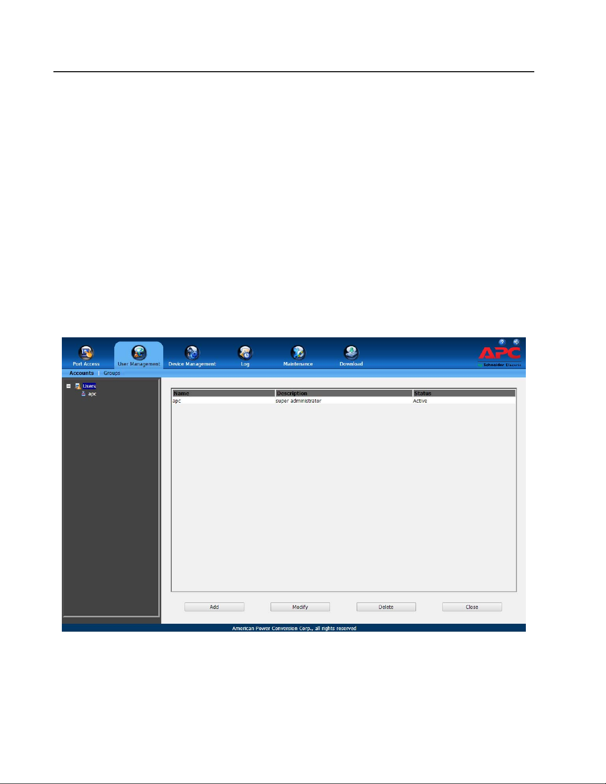
Changing the Super Administrator Login
1. At the top of the screen, click the User Management tab.
The page lists Users and Groups in the Sidebar at the left, and more details in the center panel.
The first time the page is accessed, only the Super Administrator appears.
KVM1116R User Guide16
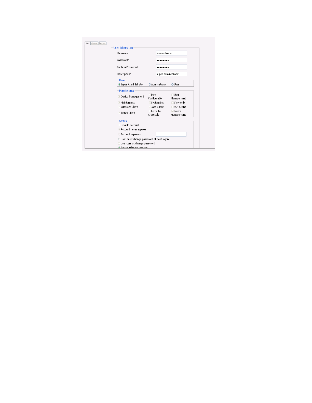
2. Click on apc in the left panel or select apc in the central panel.
Click Modify at the bottom of the page to open the User Information page.
3. Change the Username and Password.
4. Enter the new password again in the Confirm Password field and click Save.
5. Click OK in the dialog box that says the change completed successfully.
6. Click on another item on the Main Page to close the User Information page.
17KVM1116R User Guide

Logging In
KVM Switches can be accessed from a local console, an internet browser, a Windows application (AP)
program, and a Java application (AP) program.
The KVM switch authentication procedure requires a valid username and password. Invalid login
information will open an Invalid Username or Password, or Login Failed message.
NOTE: If the login fails, log in again with a correct username and password. If the number of invalid login
attempts exceeds a specified amount, a timeout period is invoked. The timeout period must expire
before another login is attempted. See Login Failures, page 64.
Available functions vary by login method.
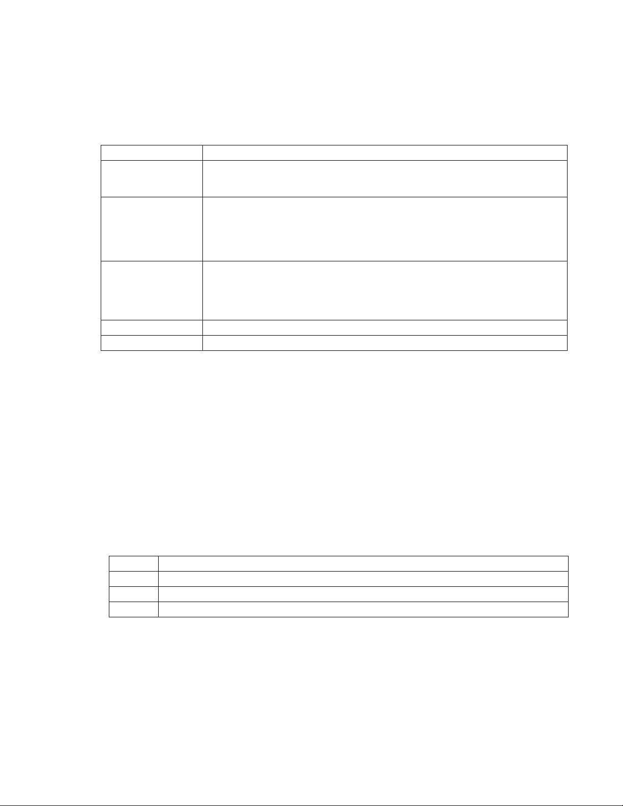
Function Local Console Browser Client AP
Main page
(Port Access >
Connections)
Port Access > User
Preferences
Device Management >
Security
Maintenance Upgrade Main Firmware
Download Not available Download WinClient, Java
Filter and Scan mode Filter mode Filter, Scan, and Array
mode
Toolbar and Beeper on/off
option
Certificate Signing
Request function
not available
and Backup/Restore
functions not available
Toolbar, Welcome
Message, and Viewer
options
Certificate Signing
Request function available
Upgrade Main Firmware
and Backup/Restore
functions available
Client, and Log server AP
Toolbar on/off option only
Certificate Signing
Request function available
Upgrade Main Firmware
and Backup/Restore
functions available
Download WinClient, Java
Client, and Log server AP
Local Console Login
Enter your Username and Password, then click Login to open the Local Console Main Page. The Local
Console Main Page is similar to the Web Browser, WinClient and Java Client Main Pages. For a
description of the Web Browser Main Page, see page 21.
Browser Login
The switch can be accessed from an Internet browser running on any platform.
1. Specify the IP address of the switch you want to access in the browser's address bar.
NOTE: If the administrator added a login string for security purposes, include a forward slash and
the login string along with the IP address when you log in.
2. When a Security Alert dialog box opens, accept the certificate. It can be trusted. If a second
certificate appears, accept it as well to open the login page.
3. Provide your username and password and click Login to open the Web Main Page.
KVM1116R User Guide18
Windows Client AP Login
The Windows AP Client allows direct remote access to Windows systems users without going through a
browser, although, initially, the Windows AP Client program must be downloaded from the browser page.
Double-click the WinClient.exe icon to open the Windows Client Connection Screen:
The Windows Client AP Connection Screen
Item Description
Menu Bar The Menu Bar contains two items: File and Help.
• The File Menu allows the operator to Create, Save, and Open user created Work files.
• The Help Menu displays the WinClient AP version.
Server List WinClient.exe searches the user's local LAN segment for switches, and lists them in this
box. Double-click to connect to one of these units.
NOTE: 1. The Enable Device List configuration parameter must be enabled.
2. Units in the Server List are those whose Access Port settings match the number
specified for Port in the Server area of this dialog box.
Server Used when connecting to a switch at a remote location. Select an address from the IP list
box. If the address isn't listed, enter the target IP address in the IP field, and its port
number in the Port field. If you don't know the port number, contact your Administrator.
• When the IP address and Port number have been specified, click Connect.
• When finished, return to this dialog box and click Disconnect to end the connection.
Message Panel Lists status messages regarding the connection to the switch.
Switch to Remote View Click to switch to the GUI Main Page (page 23).
Connect using Windows Client AP
1. Select the device from the Server List box and double-click on it, or specify its IP address and
port number in the Server IP and Port input boxes.
2. Click Connect to open the Login dialog box.
3. Enter a valid Username and Password, and click OK.
4. Following authentication, the Switch to Remote View button becomes active. Click it to connect
to the switch and bring up its GUI Main Page.
The File Menu
Create, Save, and Open user created Work files. A Work File consists of all the information specified in a
Client session including the Server List, Server IP list items, and Hotkey settings. The Client program
opens with the values contained in the current work file. The current work file consists of the values that
were in effect the last time the program was closed.
New Create a named work file so its values will not be lost, and it will be available for future recall.
Open Open a previously saved work file and use the values contained in it.
Save Save the values presently in effect as the current work file.
Exit Exits the WinClient.
19KVM1116R User Guide

Java Client AP Login
The Java AP Client provides direct remote access to non-Windows systems users although the Java AP
Client program is initially downloaded from the browser page. Double-click the JavaClient.jar icon to
open the Java Client Connection Screen.
Item Description
Server List JavaClient.jar searches the user's local LAN segment for KVM switches, and lists them in
this box. Double-click to connect to one of these units.
NOTE: 1. The switch’s Enable Device List configuration parameter must be enabled.
2. Units in the Server List are those whose Access Port settings match the number
specified for Port in the Server area of this dialog box.
Server Used when connecting to a switch at a remote location. Select an address from the IP list
box. If the address isn't listed, enter the target IP address in the IP field, and its port
number in the Port field. If you don't know the port number, contact your Administrator.
• When the IP address and Port number have been specified, click Connect.
• When finished, return to this dialog box and click Disconnect to end the connection.
Message Panel Lists status messages regarding the connection to the switch.
Switch to Remote View Click this button to switch to the GUI Main Page.
Connect using Java Client AP
To connect to a KVM switch:
1. Select the device from the Server List box and double-click on it or specify its IP address and port
number in the Server IP and Port input boxes.
2. Click Connect to open the Login dialog box.
3. Enter a valid Username and Password, and click OK.
4. Following authentication, the Switch to Remote View button becomes active. Click it to connect
to the switch and open its GUI Main Page.
KVM1116R User Guide20
The User Interface
The look of the user interface Main Page varies depending on the method used to log in.
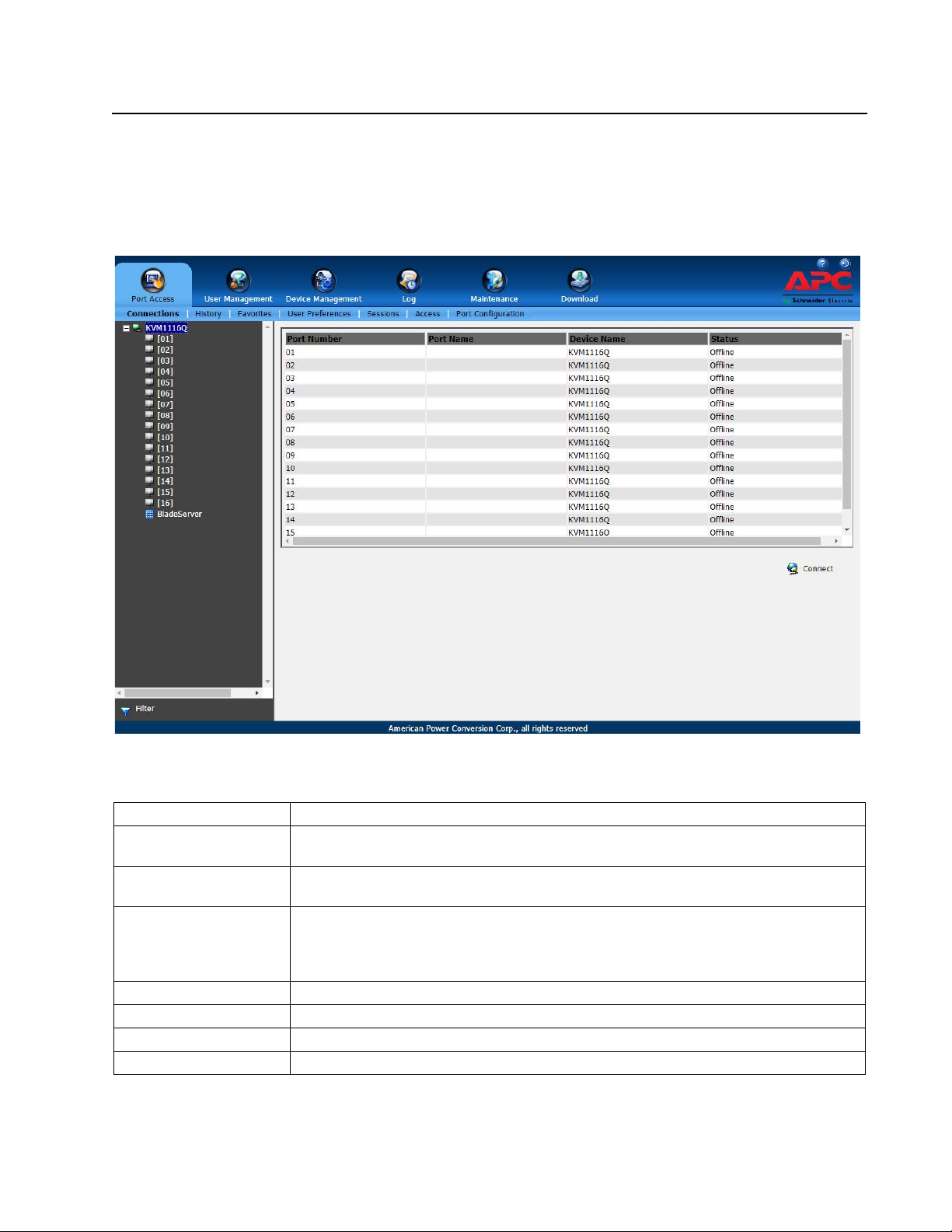
The Web Browser Main Page
Access the KVM switches with most standard web browsers. Once users log in and are authenticated,
the Web Browser Main Page opens with the Port Access page displayed.
NOTE: Depending on a user's type and permissions, not all elements appear.
Item Description
Tab Bar Contains the KVM switch main operation categories. Items appearing in the tab bar are
determined by user type and authorization options.
Menu Bar Contains operational sub-categories related to the selected item in the tab bar. Items in the
menu bar are determined by user type and authorization options.
Sidebar Provides a tree view listing of ports related to the tab bar and menu bar selections. Click an
item in the Sidebar to open a detail page. Expand or narrow the scope of the ports that
appear in the tree by clicking the Filter button at the bottom of the Sidebar. See the Filter
function on page 39 for details.
About Provides information regarding the current firmware version.
Logout Click this button to log out of your KVM switch session.
Welcome Message If enabled (see Welcome Message*, page 112), a welcome message displays here.
Interactive Display Panel The main work area. The screens reflect menu choices and Sidebar item selection.
21KVM1116R User Guide
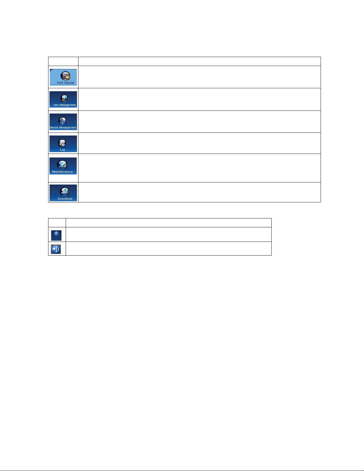
The Tab Bar
The number and type of icons that appear on the Tab Bar at the top of the page are determined by user
type (Super Administrator, Administrator, User) and permissions.
Icon Description
The Port Access page is used to access and control the devices on the KVM switch installation. This
page is available to all users.
Create and manage Users and Groups, also assign devices to them. This tab is available to the Super
Administrator, administrators, and users who have User Management permission. The tab does not
appear for other administrators and users.
Configure and control the overall operation of the KVM switch. This page is available to the Super
Administrator, administrators, and users who have Device Management permission. The tab doesn't
appear for other administrators and users.
Displays the contents of the log file.
Install new firmware; backup and restore configuration and account information; ping network devices;
and restore default values. This page is available to the Super Administrator (and Administrators and
Users with Maintenance permission). The icon does not display on the page of ordinary administrators
and users.
Download AP versions of the Windows Client, the Java Client, and the Log Server. This page is
available to all users. The programs that can be downloaded depend on the user permissions.
There are two small icons at the extreme right of the page.
Icon Description
Click the About icon to see information about the KVM switch firmware version.
Click the Logout icon to log out and end your KVM switch session.
KVM1116R User Guide22
 Loading...