

User Guide
pdu0393c
Serial
Network
10/100
by Schneider
Electric
Serial
by Schneider
Electric
Automatic
Transfer Switch
Reset
- Warning
- OK
- Overload
Network
10/100
USB
USB
Automatic
Transfer Switch
Reset
- Warning
- OK
- Overload
Rack Automatic Transfer Switch (ATS)
AP4421, AP4422, AP4423, AP4424, AP4430 , AP 443 1, AP4432,
AP4433, AP4434, AP4450, AP4452, AP4452J, AP4453,
AP4430X914
990-5844B-001
Publication Date: 8/2019
AP4452X631

APC by Schneider Electric Legal Disclaimer
The information presented in this manual is not warran ted by the APC by Schn eider Electric to be auth orit ative,
error free, or complete. This publication is not meant to be a substitute for a detailed operational and site
specific development plan. Therefore, APC by Schneider Electric assumes no liability for damages, violations of
codes, improper installation, system failures, or any other problems that could arise based on the use of this
Publication.
The information contained in this Publication is provided as is and has been prepared solely for the purpose of
evaluating data center design and construction. This Publication has been compiled in good faith by APC by
Schneider Electric. However, no representation is made or warranty given, either express or implied, as to the
completeness or accuracy of the information this Publication contains.
IN NO EVENT SHALL APC BY SCHNEIDER ELECTRIC, OR ANY PARENT, AFFILIATE OR SUBSIDIARY
COMPANY OF APC by Schneider Electric OR THEIR RESPECTIVE OFFICERS, DIRECTORS, OR
EMPLOYEES BE LIABLE FOR ANY DIRECT, INDIRECT, CONSEQUENTIAL, PUNITIVE, SPECIAL, OR
INCIDENTAL DAMAGES (INCLUDING, WITHOUT LIMITATION, DAMAGES FOR LOSS OF BUSINESS,
CONTRACT, REVENUE, DATA, INFORMATION, OR BUSINESS INTERRUPTION) RESULTING FROM,
ARISING OUT, OR IN CONNECTION WITH THE USE OF, OR INABILITY TO USE THIS PUBLICATION OR
THE CONTENT, EVEN IF APC BY SCHNEIDER ELECTRIC HAS BEEN EXPRESSLY ADVISED OF THE
POSSIBILITY OF SUCH DAMAGES. APC BY SCHNEIDER ELECTRIC RESERVES THE RIGHT TO MAKE
CHANGES OR UPDATES WITH RESPECT TO OR IN THE CONTENT OF THE PUBLICATION OR THE
FORMAT THEREOF AT ANY TIME WITHOUT NOTICE.
Copyright, intellectual, and all other proprietary right s in the content (including bu t not limited to soft ware, audio,
video, text, and photographs) rests with APC by Schneider Electric or its licensors. All rights in the content not
expressly granted herein are reserved. No rights of any kind are licensed or assigned or shall otherwise pass to
persons accessing this information.
This Publication shall not be for resale in whole or in part.

Contents
Important Safety Information.................................................................... 1
Overview..................................................................................................... 2
Product Features . . . . . . . . . . . . . . . . . . . . . . . . . . . . . . . . . . . . . . . . . . . . . . .2
Internal Protection Measures . . . . . . . . . . . . . . . . . . . . . . . . . . . . . . . . . . . . .3
How Switching Works . . . . . . . . . . . . . . . . . . . . . . . . . . . . . . . . . . . . . . . . . . .3
Types of User Accounts . . . . . . . . . . . . . . . . . . . . . . . . . . . . . . . . . . . . . . . . .5
Watchdog Features . . . . . . . . . . . . . . . . . . . . . . . . . . . . . . . . . . . . . . . . . . . . .5
Network interface watchdog mechanism . . . . . . . . . . . . . . . . . . . . . 5
Resetting the network timer . . . . . . . . . . . . . . . . . . . . . . . . . . . . . . . 5
Getting Started........................................................................................... 6
Establish Network Settings. . . . . . . . . . . . . . . . . . . . . . . . . . . . . . . . . . . . . . .6
IPv4 Initial Setup . . . . . . . . . . . . . . . . . . . . . . . . . . . . . . . . . . . . . . . . . 6
IPv6 Initial Setup . . . . . . . . . . . . . . . . . . . . . . . . . . . . . . . . . . . . . . . . . 6
TCP/IP Configuration Methods. . . . . . . . . . . . . . . . . . . . . . . . . . . . . . . . . . . .6
.ini file utility . . . . . . . . . . . . . . . . . . . . . . . . . . . . . . . . . . . . . . . . . . . . 6
Device IP Configuration Wizard . . . . . . . . . . . . . . . . . . . . . . . . . . . . 7
DHCP and BOOTP configuration . . . . . . . . . . . . . . . . . . . . . . . . . . . . 7
Local access to the CLI . . . . . . . . . . . . . . . . . . . . . . . . . . . . . . . . . . . 8
Remote access to the CLI . . . . . . . . . . . . . . . . . . . . . . . . . . . . . . . . . 9
Configure TCP/IP settings in the CLI . . . . . . . . . . . . . . . . . . . . . . . . 9
Network Management with Other Applications. . . . . . . . . . . . . . . . . . . . . .10
Recover from a Lost Password . . . . . . . . . . . . . . . . . . . . . . . . . . . . . . . . . .10
Front Panel............................................................................................... 11
Load Status LED . . . . . . . . . . . . . . . . . . . . . . . . . . . . . . . . . . . . . . . . 12
Network Status LED . . . . . . . . . . . . . . . . . . . . . . . . . . . . . . . . . . . . . 12
10/100 Status LED . . . . . . . . . . . . . . . . . . . . . . . . . . . . . . . . . . . . . . . 12
LCD Display Screens. . . . . . . . . . . . . . . . . . . . . . . . . . . . . . . . . . . . . . . . . . .13
Default screens . . . . . . . . . . . . . . . . . . . . . . . . . . . . . . . . . . . . . . . . . 13
Menu screens . . . . . . . . . . . . . . . . . . . . . . . . . . . . . . . . . . . . . . . . . . 14
Alarm status indicators . . . . . . . . . . . . . . . . . . . . . . . . . . . . . . . . . . 16
Command Line Interface......................................................................... 17
Log on to the CLI . . . . . . . . . . . . . . . . . . . . . . . . . . . . . . . . . . . . . . . . . . . . . .17
Local access to the CLI . . . . . . . . . . . . . . . . . . . . . . . . . . . . . . . . . . 17
Remote access to the CLI . . . . . . . . . . . . . . . . . . . . . . . . . . . . . . . . 17
About the Main Screen . . . . . . . . . . . . . . . . . . . . . . . . . . . . . . . . . . . . . . . . .18
Using the CLI . . . . . . . . . . . . . . . . . . . . . . . . . . . . . . . . . . . . . . . . . . . . . . . . .19
Rack ATS AP44xx User Manual i

Command Syntax. . . . . . . . . . . . . . . . . . . . . . . . . . . . . . . . . . . . . . . . . . . . . .20
Command Response Codes . . . . . . . . . . . . . . . . . . . . . . . . . . . . . . . . . . . . .21
Prompting for User Input during Command Execution . . . . . . . . . 21
Command Editing . . . . . . . . . . . . . . . . . . . . . . . . . . . . . . . . . . . . . . . . . . . . .22
History . . . . . . . . . . . . . . . . . . . . . . . . . . . . . . . . . . . . . . . . . . . . . . . . 22
Auto Completion . . . . . . . . . . . . . . . . . . . . . . . . . . . . . . . . . . . . . . . . 22
Delimiter . . . . . . . . . . . . . . . . . . . . . . . . . . . . . . . . . . . . . . . . . . . . . . . 22
Options and Arguments Inputs . . . . . . . . . . . . . . . . . . . . . . . . . . . . . . . . . .23
Command Console and CLI Response Format . . . . . . . . . . . . . . . 23
Response Format and Message Codes . . . . . . . . . . . . . . . . . . . . . . 23
Rack ATS System Command Descriptions. . . . . . . . . . . . . . . . . . . . . . . . .24
? or help . . . . . . . . . . . . . . . . . . . . . . . . . . . . . . . . . . . . . . . . . . . . . . . 24
about . . . . . . . . . . . . . . . . . . . . . . . . . . . . . . . . . . . . . . . . . . . . . . . . . . 25
alarmcount . . . . . . . . . . . . . . . . . . . . . . . . . . . . . . . . . . . . . . . . . . . . . 26
boot . . . . . . . . . . . . . . . . . . . . . . . . . . . . . . . . . . . . . . . . . . . . . . . . . . . 27
bye, exit, or quit . . . . . . . . . . . . . . . . . . . . . . . . . . . . . . . . . . . . . . . . . 28
cd . . . . . . . . . . . . . . . . . . . . . . . . . . . . . . . . . . . . . . . . . . . . . . . . . . . . 28
cipher . . . . . . . . . . . . . . . . . . . . . . . . . . . . . . . . . . . . . . . . . . . . . . . . . 29
clrrst . . . . . . . . . . . . . . . . . . . . . . . . . . . . . . . . . . . . . . . . . . . . . . . . . . 31
console . . . . . . . . . . . . . . . . . . . . . . . . . . . . . . . . . . . . . . . . . . . . . . . . 31
date . . . . . . . . . . . . . . . . . . . . . . . . . . . . . . . . . . . . . . . . . . . . . . . . . . . 32
delete . . . . . . . . . . . . . . . . . . . . . . . . . . . . . . . . . . . . . . . . . . . . . . . . . 32
dir . . . . . . . . . . . . . . . . . . . . . . . . . . . . . . . . . . . . . . . . . . . . . . . . . . . . 33
dns . . . . . . . . . . . . . . . . . . . . . . . . . . . . . . . . . . . . . . . . . . . . . . . . . . . 34
eapol . . . . . . . . . . . . . . . . . . . . . . . . . . . . . . . . . . . . . . . . . . . . . . . . . . 35
email . . . . . . . . . . . . . . . . . . . . . . . . . . . . . . . . . . . . . . . . . . . . . . . . . . 36
eventlog . . . . . . . . . . . . . . . . . . . . . . . . . . . . . . . . . . . . . . . . . . . . . . . 37
exit . . . . . . . . . . . . . . . . . . . . . . . . . . . . . . . . . . . . . . . . . . . . . . . . . . . 37
firewall . . . . . . . . . . . . . . . . . . . . . . . . . . . . . . . . . . . . . . . . . . . . . . . . 38
format . . . . . . . . . . . . . . . . . . . . . . . . . . . . . . . . . . . . . . . . . . . . . . . . . 38
ftp . . . . . . . . . . . . . . . . . . . . . . . . . . . . . . . . . . . . . . . . . . . . . . . . . . . . 39
help . . . . . . . . . . . . . . . . . . . . . . . . . . . . . . . . . . . . . . . . . . . . . . . . . . . 39
lang . . . . . . . . . . . . . . . . . . . . . . . . . . . . . . . . . . . . . . . . . . . . . . . . . . . 39
lastrst . . . . . . . . . . . . . . . . . . . . . . . . . . . . . . . . . . . . . . . . . . . . . . . . . 40
ledblink . . . . . . . . . . . . . . . . . . . . . . . . . . . . . . . . . . . . . . . . . . . . . . . . 40
logzip . . . . . . . . . . . . . . . . . . . . . . . . . . . . . . . . . . . . . . . . . . . . . . . . . 40
netstat . . . . . . . . . . . . . . . . . . . . . . . . . . . . . . . . . . . . . . . . . . . . . . . . . 41
ntp . . . . . . . . . . . . . . . . . . . . . . . . . . . . . . . . . . . . . . . . . . . . . . . . . . . . 41
ping . . . . . . . . . . . . . . . . . . . . . . . . . . . . . . . . . . . . . . . . . . . . . . . . . . . 42
portSpeed . . . . . . . . . . . . . . . . . . . . . . . . . . . . . . . . . . . . . . . . . . . . . . 42
prompt . . . . . . . . . . . . . . . . . . . . . . . . . . . . . . . . . . . . . . . . . . . . . . . . 43
pwd . . . . . . . . . . . . . . . . . . . . . . . . . . . . . . . . . . . . . . . . . . . . . . . . . . . 43
radius . . . . . . . . . . . . . . . . . . . . . . . . . . . . . . . . . . . . . . . . . . . . . . . . . 44
reboot . . . . . . . . . . . . . . . . . . . . . . . . . . . . . . . . . . . . . . . . . . . . . . . . . 45
resetToDef . . . . . . . . . . . . . . . . . . . . . . . . . . . . . . . . . . . . . . . . . . . . . 45
session . . . . . . . . . . . . . . . . . . . . . . . . . . . . . . . . . . . . . . . . . . . . . . . . 46
smtp . . . . . . . . . . . . . . . . . . . . . . . . . . . . . . . . . . . . . . . . . . . . . . . . . . 47
Rack ATS AP44xx User Manualii

snmp . . . . . . . . . . . . . . . . . . . . . . . . . . . . . . . . . . . . . . . . . . . . . . . . . .48
snmpv3 . . . . . . . . . . . . . . . . . . . . . . . . . . . . . . . . . . . . . . . . . . . . . . . .49
snmptrap . . . . . . . . . . . . . . . . . . . . . . . . . . . . . . . . . . . . . . . . . . . . . . .50
system . . . . . . . . . . . . . . . . . . . . . . . . . . . . . . . . . . . . . . . . . . . . . . . . .51
tcpip . . . . . . . . . . . . . . . . . . . . . . . . . . . . . . . . . . . . . . . . . . . . . . . . . .52
tcpip6 . . . . . . . . . . . . . . . . . . . . . . . . . . . . . . . . . . . . . . . . . . . . . . . . .53
user . . . . . . . . . . . . . . . . . . . . . . . . . . . . . . . . . . . . . . . . . . . . . . . . . . .54
userdflt . . . . . . . . . . . . . . . . . . . . . . . . . . . . . . . . . . . . . . . . . . . . . . . . 55
web . . . . . . . . . . . . . . . . . . . . . . . . . . . . . . . . . . . . . . . . . . . . . . . . . . .56
whoami . . . . . . . . . . . . . . . . . . . . . . . . . . . . . . . . . . . . . . . . . . . . . . . .56
xferINI . . . . . . . . . . . . . . . . . . . . . . . . . . . . . . . . . . . . . . . . . . . . . . . . . 57
xferStatus . . . . . . . . . . . . . . . . . . . . . . . . . . . . . . . . . . . . . . . . . . . . . .57
Device Command Descriptions . . . . . . . . . . . . . . . . . . . . . . . . . . . . . . . . . .58
aboutATS . . . . . . . . . . . . . . . . . . . . . . . . . . . . . . . . . . . . . . . . . . . . . .58
atsStatus . . . . . . . . . . . . . . . . . . . . . . . . . . . . . . . . . . . . . . . . . . . . . . .58
atsMeasure . . . . . . . . . . . . . . . . . . . . . . . . . . . . . . . . . . . . . . . . . . . . . 59
bkLowLoad . . . . . . . . . . . . . . . . . . . . . . . . . . . . . . . . . . . . . . . . . . . . .60
bkNearOver . . . . . . . . . . . . . . . . . . . . . . . . . . . . . . . . . . . . . . . . . . . . .61
bkOverLoad . . . . . . . . . . . . . . . . . . . . . . . . . . . . . . . . . . . . . . . . . . . .62
bkPeakLoad . . . . . . . . . . . . . . . . . . . . . . . . . . . . . . . . . . . . . . . . . . . .63
bkReading . . . . . . . . . . . . . . . . . . . . . . . . . . . . . . . . . . . . . . . . . . . . . .64
eventCounts . . . . . . . . . . . . . . . . . . . . . . . . . . . . . . . . . . . . . . . . . . . . 65
freqDeviat . . . . . . . . . . . . . . . . . . . . . . . . . . . . . . . . . . . . . . . . . . . . . .65
frontPanel . . . . . . . . . . . . . . . . . . . . . . . . . . . . . . . . . . . . . . . . . . . . . . 66
lcd . . . . . . . . . . . . . . . . . . . . . . . . . . . . . . . . . . . . . . . . . . . . . . . . . . . . 66
lcdBlink . . . . . . . . . . . . . . . . . . . . . . . . . . . . . . . . . . . . . . . . . . . . . . . .66
lineVRMS . . . . . . . . . . . . . . . . . . . . . . . . . . . . . . . . . . . . . . . . . . . . . .67
phLowLoad . . . . . . . . . . . . . . . . . . . . . . . . . . . . . . . . . . . . . . . . . . . . . 67
phNearOver . . . . . . . . . . . . . . . . . . . . . . . . . . . . . . . . . . . . . . . . . . . .68
phOverLoad . . . . . . . . . . . . . . . . . . . . . . . . . . . . . . . . . . . . . . . . . . . . 68
phPeakLoad . . . . . . . . . . . . . . . . . . . . . . . . . . . . . . . . . . . . . . . . . . . .6 8
phReading . . . . . . . . . . . . . . . . . . . . . . . . . . . . . . . . . . . . . . . . . . . . .69
prodInfo . . . . . . . . . . . . . . . . . . . . . . . . . . . . . . . . . . . . . . . . . . . . . . .69
sourceAName . . . . . . . . . . . . . . . . . . . . . . . . . . . . . . . . . . . . . . . . . . .69
sourceBName . . . . . . . . . . . . . . . . . . . . . . . . . . . . . . . . . . . . . . . . . . .70
sourcePref . . . . . . . . . . . . . . . . . . . . . . . . . . . . . . . . . . . . . . . . . . . . . 70
vMediumLmt . . . . . . . . . . . . . . . . . . . . . . . . . . . . . . . . . . . . . . . . . . . .70
vNarrowLmt . . . . . . . . . . . . . . . . . . . . . . . . . . . . . . . . . . . . . . . . . . . .71
vSensitvty . . . . . . . . . . . . . . . . . . . . . . . . . . . . . . . . . . . . . . . . . . . . . .71
vWideLmt . . . . . . . . . . . . . . . . . . . . . . . . . . . . . . . . . . . . . . . . . . . . . .72
vXferRange . . . . . . . . . . . . . . . . . . . . . . . . . . . . . . . . . . . . . . . . . . . . .72
Web User Interface .................................................................................. 73
Log on to the Web UI. . . . . . . . . . . . . . . . . . . . . . . . . . . . . . . . . . . . . . . . . . .73
URL address formats . . . . . . . . . . . . . . . . . . . . . . . . . . . . . . . . . . . . .74
First log on . . . . . . . . . . . . . . . . . . . . . . . . . . . . . . . . . . . . . . . . . . . . .74
Limited Status Access . . . . . . . . . . . . . . . . . . . . . . . . . . . . . . . . . . . . 74
Rack ATS AP44xx User Manual iii

Web UI Features. . . . . . . . . . . . . . . . . . . . . . . . . . . . . . . . . . . . . . . . . . . . . . .75
Tabs . . . . . . . . . . . . . . . . . . . . . . . . . . . . . . . . . . . . . . . . . . . . . . . . . . 75
Limited Status Access . . . . . . . . . . . . . . . . . . . . . . . . . . . . . . . . . . . 75
Device status icons . . . . . . . . . . . . . . . . . . . . . . . . . . . . . . . . . . . . . . 75
Quick Links . . . . . . . . . . . . . . . . . . . . . . . . . . . . . . . . . . . . . . . . . . . . 75
Home Tab..................................................................................................77
Status Tab.................................................................................................78
View ATS Status. . . . . . . . . . . . . . . . . . . . . . . . . . . . . . . . . . . . . . . . . . . . . . .78
View device alarms . . . . . . . . . . . . . . . . . . . . . . . . . . . . . . . . . . . . . . 78
View device status . . . . . . . . . . . . . . . . . . . . . . . . . . . . . . . . . . . . . . . 78
View the unit status . . . . . . . . . . . . . . . . . . . . . . . . . . . . . . . . . . . . . . 78
View load status . . . . . . . . . . . . . . . . . . . . . . . . . . . . . . . . . . . . . . . . 78
View power measurements . . . . . . . . . . . . . . . . . . . . . . . . . . . . . . . 78
View Network Status . . . . . . . . . . . . . . . . . . . . . . . . . . . . . . . . . . . . . . . . . . .79
Current IPv4 settings . . . . . . . . . . . . . . . . . . . . . . . . . . . . . . . . . . . . 79
Current IPv6 settings . . . . . . . . . . . . . . . . . . . . . . . . . . . . . . . . . . . . 79
Domain name system status . . . . . . . . . . . . . . . . . . . . . . . . . . . . . . 80
Port Speed . . . . . . . . . . . . . . . . . . . . . . . . . . . . . . . . . . . . . . . . . . . . . 80
Control Tab...............................................................................................81
Manage User Sessions . . . . . . . . . . . . . . . . . . . . . . . . . . . . . . . . . . . . . . . . .81
Reset the Network Interface . . . . . . . . . . . . . . . . . . . . . . . . . . . . . . . . . . . . .82
Configuration Tab.................................................................................... 83
Configure the ATS . . . . . . . . . . . . . . . . . . . . . . . . . . . . . . . . . . . . . . . . . . . . .83
Configure ATS name and location . . . . . . . . . . . . . . . . . . . . . . . . . . 83
Set preferred power source . . . . . . . . . . . . . . . . . . . . . . . . . . . . . . . 83
Configure switching behavior . . . . . . . . . . . . . . . . . . . . . . . . . . . . . 84
Configure warning thresholds . . . . . . . . . . . . . . . . . . . . . . . . . . . . . 85
Manage Security Settings . . . . . . . . . . . . . . . . . . . . . . . . . . . . . . . . . . . . . . .86
Manage user sessions . . . . . . . . . . . . . . . . . . . . . . . . . . . . . . . . . . . 86
Enable ping response . . . . . . . . . . . . . . . . . . . . . . . . . . . . . . . . . . . . 86
Manage local user settings . . . . . . . . . . . . . . . . . . . . . . . . . . . . . . . . 87
Configure default user settings . . . . . . . . . . . . . . . . . . . . . . . . . . . . 89
Manage remote user settings . . . . . . . . . . . . . . . . . . . . . . . . . . . . . . 91
Configure a RADIUS server . . . . . . . . . . . . . . . . . . . . . . . . . . . . . . . 92
Firewall menus . . . . . . . . . . . . . . . . . . . . . . . . . . . . . . . . . . . . . . . . . . 93
802.1X Security Configuration . . . . . . . . . . . . . . . . . . . . . . . . . . . . . 95
Configure Network Settings . . . . . . . . . . . . . . . . . . . . . . . . . . . . . . . . . . . . .96
Configure TCP/IP and communication settings for IPv4 and IPv6 96
Configure network port speed . . . . . . . . . . . . . . . . . . . . . . . . . . . . . 98
Configure DNS . . . . . . . . . . . . . . . . . . . . . . . . . . . . . . . . . . . . . . . . . . 99
Test DNS configuration . . . . . . . . . . . . . . . . . . . . . . . . . . . . . . . . . . . 99
Configure Web access . . . . . . . . . . . . . . . . . . . . . . . . . . . . . . . . . . 100
Rack ATS AP44xx User Manualiv

Configure SSL certificate . . . . . . . . . . . . . . . . . . . . . . . . . . . . . . . .101
Configure CLI access . . . . . . . . . . . . . . . . . . . . . . . . . . . . . . . . . . .101
Configure SSH host key . . . . . . . . . . . . . . . . . . . . . . . . . . . . . . . . . 102
SNMP options . . . . . . . . . . . . . . . . . . . . . . . . . . . . . . . . . . . . . . . . . .102
SNMPv1 . . . . . . . . . . . . . . . . . . . . . . . . . . . . . . . . . . . . . . . . . . . . . . .103
SNMPv3 . . . . . . . . . . . . . . . . . . . . . . . . . . . . . . . . . . . . . . . . . . . . . . .104
Configure FTP server . . . . . . . . . . . . . . . . . . . . . . . . . . . . . . . . . . .105
Configure Notifications . . . . . . . . . . . . . . . . . . . . . . . . . . . . . . . . . . . . . . . .106
Configure notifications by event . . . . . . . . . . . . . . . . . . . . . . . . . .106
Configure notifications by group . . . . . . . . . . . . . . . . . . . . . . . . . .107
Set up e-mail notifications . . . . . . . . . . . . . . . . . . . . . . . . . . . . . . .108
SNMP traps . . . . . . . . . . . . . . . . . . . . . . . . . . . . . . . . . . . . . . . . . . . .111
General Configuration. . . . . . . . . . . . . . . . . . . . . . . . . . . . . . . . . . . . . . . . .112
Configure identification . . . . . . . . . . . . . . . . . . . . . . . . . . . . . . . . . .112
Configure date, time, and daylight savings . . . . . . . . . . . . . . . . . .113
Create and import settings with the config file . . . . . . . . . . . . . . .114
Configure links . . . . . . . . . . . . . . . . . . . . . . . . . . . . . . . . . . . . . . . . .114
Configure Logs. . . . . . . . . . . . . . . . . . . . . . . . . . . . . . . . . . . . . . . . . . . . . . .114
Identify Syslog servers . . . . . . . . . . . . . . . . . . . . . . . . . . . . . . . . . .114
Configure Syslog settings . . . . . . . . . . . . . . . . . . . . . . . . . . . . . . . 115
Test Syslog servers . . . . . . . . . . . . . . . . . . . . . . . . . . . . . . . . . . . . . 115
Tests Tab................................................................................................ 116
Set the LCD/LED Lights to Blink. . . . . . . . . . . . . . . . . . . . . . . . . . . . . . . . .116
Set the LED Lights to Blink. . . . . . . . . . . . . . . . . . . . . . . . . . . . . . . . . . . . .116
Logs Tab................................................................................................. 117
View and configure the Event Log . . . . . . . . . . . . . . . . . . . . . . . . . . . . . . .117
View and configure the Data Log . . . . . . . . . . . . . . . . . . . . . . . . . . . . . . . .119
Firewall log . . . . . . . . . . . . . . . . . . . . . . . . . . . . . . . . . . . . . . . . . . . .120
Use FTP or SCP to retrieve log files . . . . . . . . . . . . . . . . . . . . . . . . 120
About Tab............................................................................................... 122
About the Rack ATS. . . . . . . . . . . . . . . . . . . . . . . . . . . . . . . . . . . . . . . . . . .122
About the network . . . . . . . . . . . . . . . . . . . . . . . . . . . . . . . . . . . . . . . . . . . .122
Support resources. . . . . . . . . . . . . . . . . . . . . . . . . . . . . . . . . . . . . . . . . . . .122
How to Export Configuration Settings................................................. 123
Summary of the procedure . . . . . . . . . . . . . . . . . . . . . . . . . . . . . . . . . . . . .123
Contents of the .ini file . . . . . . . . . . . . . . . . . . . . . . . . . . . . . . . . . . . . . . . .123
Detailed procedures. . . . . . . . . . . . . . . . . . . . . . . . . . . . . . . . . . . . . . . . . . .124
Retrieve .ini file . . . . . . . . . . . . . . . . . . . . . . . . . . . . . . . . . . . . . . . .124
Edit .ini file . . . . . . . . . . . . . . . . . . . . . . . . . . . . . . . . . . . . . . . . . . . .124
Transfer the file to a single ATS . . . . . . . . . . . . . . . . . . . . . . . . . . . 125
Transfer the file to multiple ATS units . . . . . . . . . . . . . . . . . . . . . . 125
Rack ATS AP44xx User Manual v

The Upload Event and Error Messages . . . . . . . . . . . . . . . . . . . . . . . . . . .126
The event and its error messages . . . . . . . . . . . . . . . . . . . . . . . . . 126
Messages in config.ini . . . . . . . . . . . . . . . . . . . . . . . . . . . . . . . . . . 126
Errors generated by overridden values . . . . . . . . . . . . . . . . . . . . . 126
Related Topics . . . . . . . . . . . . . . . . . . . . . . . . . . . . . . . . . . . . . . . . . . . . . . .126
File Transfers ......................................................................................... 127
Upgrading Firmware . . . . . . . . . . . . . . . . . . . . . . . . . . . . . . . . . . . . . . . . . .127
Benefits of upgrading firmware . . . . . . . . . . . . . . . . . . . . . . . . . . . 127
Firmware module files . . . . . . . . . . . . . . . . . . . . . . . . . . . . . . . . . . . 127
Firmware File Transfer Methods. . . . . . . . . . . . . . . . . . . . . . . . . . . . . . . . . 128
Use the Firmware Upgrade Utility . . . . . . . . . . . . . . . . . . . . . . . . . 128
Use FTP or SCP to upgrade one Rack ATS . . . . . . . . . . . . . . . . . . 128
Use XMODEM to upgrade one Rack ATS . . . . . . . . . . . . . . . . . . . 129
Use a USB drive to transfer and upgrade files . . . . . . . . . . . . . . . 130
How to upgrade multiple ATS units . . . . . . . . . . . . . . . . . . . . . . . . 130
Use the Firmware Upgrade Utility for multiple upgrades . . . . . . 130
Verifying Upgrades and Updates . . . . . . . . . . . . . . . . . . . . . . . . . . . . . . . .131
Verify the success or failure of the transfer . . . . . . . . . . . . . . . . . 131
Last Transfer Result codes . . . . . . . . . . . . . . . . . . . . . . . . . . . . . . 131
Verify the version numbers of installed firmware . . . . . . . . . . . . 131
Troubleshooting.....................................................................................132
Rack ATS Access Problems. . . . . . . . . . . . . . . . . . . . . . . . . . . . . . . . . . . .132
SNMP Issues . . . . . . . . . . . . . . . . . . . . . . . . . . . . . . . . . . . . . . . . . . . . . . . .133
Source Code Copyright Notice.............................................................134
Rack ATS AP44xx User Manualvi

Important Safety Information
Read the instructions carefully to become familiar with the equipment before trying to install, operate,
service, or maintain it. The following special messages may appear throughout this manual or on the
equipment to warn of potential hazards or to call attention to information that clarifies or simplifies a
procedure.
The addition of this symbol to a Danger or Warning safety label indicates that an electrical
hazard exists which will result in personal injury if the instructions are not followed.
This is the safety alert symbol. It is used to alert you to potential personal injury hazards.
Obey all safety messages that follow this symbol to avoid possible injury or death.
DANGER
DANGER indicates an imminently hazardous situation which, if not avoided, will result in death
or serious injury.
WARNING
WARNING indicates a potentially hazardous situation which, if not avoided, can result in death
or serious injury.
CAUTION
CAUTION indicates a potentially hazardous situation which, if not avoided, can result in minor or
moderate injury.
NOTICE
NOTICE addresses practices not related to physical injury including certain environmental
hazards, potential damage or loss of data.
1Rack ATS AP44xx User Manual

Overview
The APC by Schneider Electric™ Rack Automatic Transfer Switch (ATS) with Network Management
Card 2 provides redundant power to single-corded e quipment loads, such as servers. The Rack ATS has
two input power cords that supply power to the connected loads from both a primary and secondary
power source. If the primary source becomes unavailable or goe s out of the con figured powe r range, the
Rack ATS will switch to draw power from the secondary source without interrupting critical loads. You
can manage a Rack ATS through its Web User Interface (Web UI), its Command Line Interface (CLI),
StruxureWare™ Data Center Expert
(SNMP). (To use the PowerNet
(MIB) Reference Guide, available at www.apc.com.)
Product Features
The Rack ATS has these additional features:
• LED indicators on the front panel of the unit indicate operation conditions such as preferred
source, overload current, and Web connectivity. These conditions can also be monitored via the
CLI and Web UI.
• Various levels of access: Super User, Administrator, Device User, Read-Only, and Network-Only
User. (These have user name and password requirements.)
• A multiple-user login feature, which allows up to four users to be logged in simultaneously.
• Event and data logging. The event log is accessible by Telnet, Secure CoPy (SCP), File Transfer
Protocol (FTP), serial connection, or Web browser (using HTTPS access with SSL/TLS, or using
HTTP access). The data log is accessible by Web browser, SCP, or FTP.
• SNMP traps, Syslog messages, and e-mail notifications based on the severity level or category of
the Rack ATS and NMC system event.
• Security protocols for authentication and encryption.
• The ability to monitor sources and set source-transfer parameters via Web and CLI interfaces.
• Set alarm thresholds that provide network and visual alarms to help you prevent overloaded
circuits.
• Internal protection measures against short circuit s. (See “Internal Protection Measur es” on page 3
for details.)
NOTE: It is always recommended that you connect each ATS source to a Double Conversion
On-Line Uninterruptible Power Supply (UPS).
®
, EcoStruxure IT, or Simple Network Management Protocol
®
MIB with an SNMP browser, see the Management Information Base
Rack ATS AP44xx User Manual2
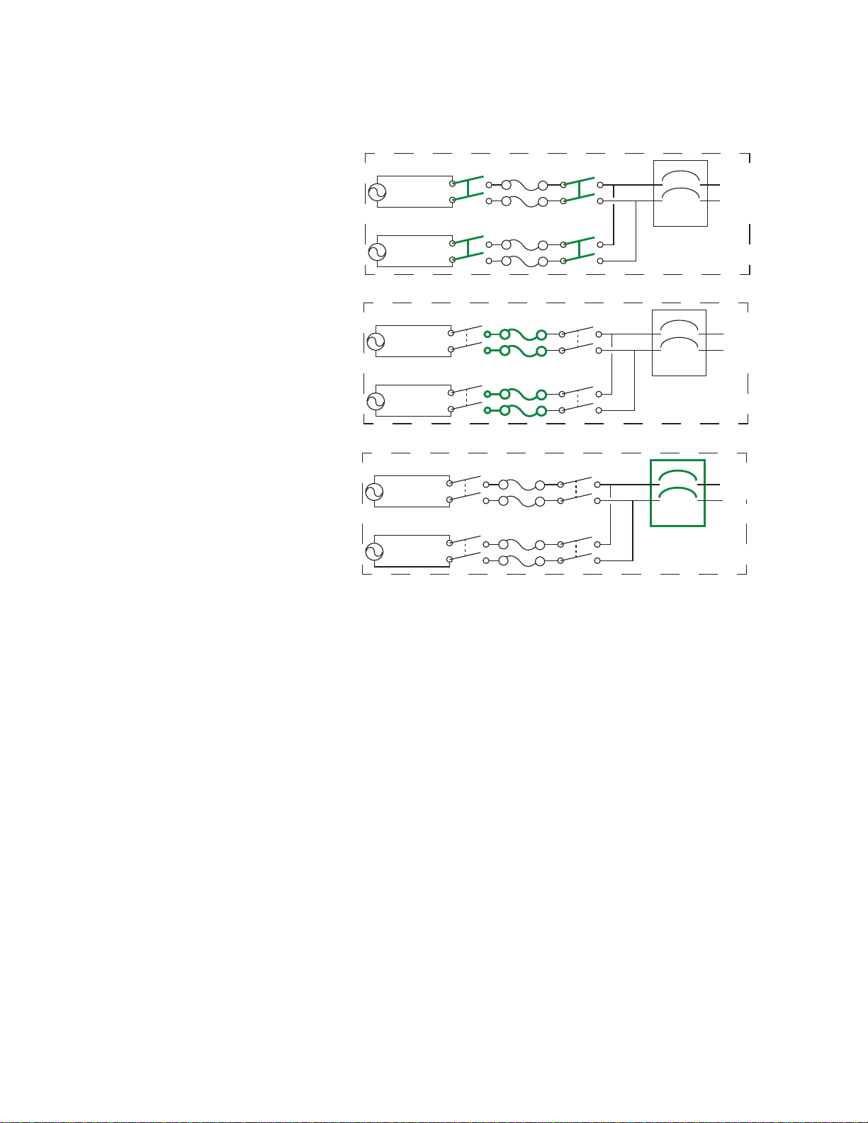
Internal Protection Measures
Source A
Source B
Load
ATS 1
Source A
Source B
Load
ATS 2
Source A
Source B
Load
ATS 3
Attached
equipment
Attached
equipment
Attached
equipment
ATS units may include the following internal protection measures:
• Input relays in ever y
model open when their
source is
disconnected to help
prevent electric
backfeed from one
input cord into another
(ATS 1).
• Two or four
non-replaceable fuses
(depending on the
model) help to prot ect
the ATS from short
circuits (ATS 2).
• Some 2U models have
circuit breakers to
help protect against
bank overload (ATS
3).
The rack ATS does not include power surge protection. To help protect your ATS from external power
surges, it is always recommended that you connect each ATS source to a Double Conversion On-Line
Uninterruptible Power Supply (UPS).
How Switching Works
1. You configure the ATS to accept power that meets the needs of your equipment by adjusting the
following settings (see “Configuration Tab” on page 83 for more details).
– Line VRMS: The ideal voltage for your equipment. Acceptable line voltages vary per ATS
model (see the specification sheet for your ATS model on www.apc.com).
– Transfer limits: The maximum and minimum voltages the ATS will accept before switching
sources. Transfer limits are meant to allow for small, acceptable surges and drops in power.
The ATS should not operate near the upper transfer limit for long periods of time.
– Transfer ranges: Pre-defined sets of transfer limits. You can configure up to three transfer
ranges, but you can enable only one transfer range at a time.
– Sensitivity: How long the A TS waits to determine whether or not it will switch sources.
High sensitivity provides extra responsiveness for delicate equipment. Low sensitivity helps to
prevent excessive switching in cases of fluctuating power inputs.
pdu0777a
3Rack ATS AP44xx User Manual
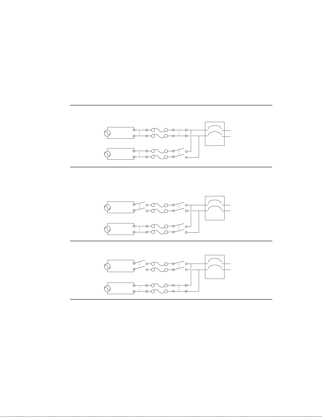
2. The ATS constantly monitors the quality and amount of power coming from sources A and B. If
pdu0776a
Source A
Source B
Attached Equipment
Source A
Source B
Attached Equipment
Source A
Source B
Attached Equipment
Source A is providing power to the attached equipment, while Source B is isolated from
the attached equipment.
Firmware detects that Source A is out of the user-specified transfer range. The input
power from Source A is removed by disengaging the relays. (This allows for
out-of-phase switching and significantly reduces the opportunity for relay welding.)
Source B relays are engaged; Source B provides power to the attached equipment.
one source begins to supply power that does not meet your settings, the ATS will disqualify that
source.
a. If the disqualified source is not in use, the ATS will generate an alarm to indicate that
redundancy has been lost.
b. If the disqualified source is in use, the ATS will switch to draw power from the other
available source.
If a preferred source is set, the A TS will wait 30 seconds to monitor that source. After 30 seconds,
if the preferred source becomes usable again, the ATS will switch back to the preferred source.
See how the switch happens in the illustration below.
NOTE: The entire switching process (described in step 2) takes a maximum of
10 milliseconds (ms) at high sensitivity, and 12 ms at low sensitivity. (This applies to both 50 Hz
and 60 Hz sources.)
Rack ATS AP44xx User Manual4

Types of User Accounts
The Rack A TS has various levels of access (Super User, Administrator, Device User, Read-Only User,
and Network-Only User), which are protected by user name and password requirements. Up to four
users are allowed to log on to the same Rack ATS simultaneously.
NOTE: You will be prompted to enter a new password the first time you connect to the device with the
Super User account. The Administrator, Device User, Read-Only User, and Network-Only user accounts
are disabled by default, and cannot be enabled until the Super User default password (apc) is changed.
• An Administrator or the Super User can use all of the menus in the Web UI and all of the
commands in the CLI. Administrator user types can be deleted, but the Super User cannot
be deleted. The default user name and password for the Super User or an Administrator are
both apc.
NOTE: The Super User or an Administrator can manage another Administrator's account
(enable, disable, change password, etc).
• A Device User has read and write access to device-related screens. Adminis trative functions like
Session Management under the Security menu and Firewall under Logs are unavailable.
• A Read-Only User has access to the same menus as a Device User, but without the ability to
change configurations, control devices, delete data, or use file transfer options. Links to
configuration options are visible but disab l ed . Th e even t an d da ta logs display no but ton to cle ar
the log. The default user name for this account is readonly, and the default password is apc.
• A Network-Only User can only log on using the Web UI and CLI (Telnet or SSH). A user with
network-only access has read/write permission to the network related menus only.
Watchdog Features
To detect internal problems and recover from unanticipated inputs, the Rack ATS uses internal, systemwide watchdog mechanisms. When it restarts to reco ver from an internal problem, a Network Interface
Restarted event is recorded in the event log.
Network interface watchdog mechanism
The Rack ATS implements internal watchdog mechanisms to help protect itself from becoming
inaccessible over the network. For example, if the Rack ATS does not receive any network traffic for 9.5
minutes (either direct traffic, such as SNMP, or broadcast traffic, such as an Address Resolution Protocol
[ARP] request), it assumes that there is a problem with its network interface and restarts. The network
interface watchdog mechanism is only enabled on an ATS that discovers an active network interface
connection at start-up.
Resetting the network timer
To help ensure that the Rack ATS does not restart if the network is quiet for 9.5 minutes, the Rack ATS
attempts to contact the default gateway every 4.5 minu tes. If the gateway is present, it responds to the
Rack A TS, an d the r esponse restarts the 9.5-minute timer. If your applica tion do es not require or have a
gateway , specify the IP addr ess of a computer that is runn ing on the network and is on the same subn et.
The network traffic of that computer should resta rt the 9.5-minute time frequently enough to prevent the
Rack ATS from restarting.
5Rack ATS AP44xx User Manual

Getting Started
To start using the Rack ATS:
1. Install the Rack ATS using the Installation and Quick Start on www.apc.com.
2. Apply power and connect to your network. Follow the directions in the Installation and Quick
Start.
3. Establish your network settings.
4. Begin using the Rack ATS with one of the following:
– The front panel. See “Front Panel” on page 11.
NOTE: The front panel allows you to view Rack ATS settings, but not configure them.
– The CLI. See “Command Line Interface” on page 17.
– The Web UI. See “Web User Interface” on page73.
Establish Network Settings
IPv4 Initial Setup
You must define three TCP/IP settings for the Rack ATS before it can operate on the network:
• The IP address of the Rack ATS
• The subnet mask of the Rack ATS
• The IP address of the default gateway (only needed if you are going off segment)
NOTE: Do NOT use the loopback address (127.0.0.1) as the defa ult gateway. Doing so disables the
network connection of the Rack ATS. To enable the network connection again, you must log on using a
serial connection and reset the TCP/IP settings to their defaults.
For detailed information on how to use a DHCP server to configure the TCP/IP settings at a Rack ATS,
see.“DHCP response options” on page 96
IPv6 Initial Setup
IPv6 network configuration provides flexibility to accommodate your requirements. IPv6 can be used
anywhere an IP address is entered on this interface. You can configure IPv6 using the CLI, the Web UI,
or DHCP.
TCP/IP Configuration Methods
Use one of the following methods to define the TCP/IP settings needed by the Rack ATS:
• Device IP Configuration Wizard (see “Device IP Configuration Wizard” on this page).
• BOOTP or DHCP server (see “DHCP and BOOTP configuration” on page 7).
• Local computer (see “Local access to the CLI” on page 8).
• Networked computer (see “Remote access to the CLI” on page 9).
.ini file utility
You can use the .ini file export utility to export .ini file settings from a configured Rack ATS to an
unconfigured Rack ATS. For more information, see “Create and import settings with the config file” on
page 114.
Rack ATS AP44xx User Manual6

Device IP Configuration Wizard
The Device IP Configuration Wizard runs on Microsoft® Windows® 2000, Windows Server® 2003,
Windows Server 2012, and on 32- and 64-bit versions of Windows XP
2008, Windows 7, Windows 8, and Windows 10 operating systems. The Device IP Configuration Wizard
supports cards that have firmware version 3.0.x or higher and is for IPv4 only.
To install the Device IP Configuration Wizard:
1. Go to www.apc.com.
2. Download the latest version of the Device IP Configuration Wizard.
3. Run the executable file (DeviceIPConfigurationWizard.exe).
NOTE: If you leave the Start a Web browser when finished option enabled, you can use apc
for both the user name and password to access the Rack ATS through your browser.
When Installed, the Device IP configuration Wizard is available through the Windows Start menu
options.
Configure TCP/IP settings with the Wizard
The Device IP Configuration Wizard can discover Rack ATS units that do not have an IP address
assigned. Once discovered, you can configure the IP address settings for the Network Management
Cards (NMCs).You can also search for devices already on the network by e ntering an IP ra nge to define
the search. The Utility scans the IP addresses in the defined range and discovers Rack ATS units that
already have a DHCP-assigned IP address.
NOTE: For detailed information on the Utility , see FAQ article FA156064: go to www.apc.com, navigate
to Support > Resources & Tools > FAQS, then enter the article number in the search bar.
®
, Windows Vista®, Windows
NOTE: To use the DHCP Option 12 (AOS 5.1.5 or higher), see FAQ article FA156110.
DHCP and BOOTP configuration
The default TCP/IP configuration setting, DHCP, assumes that a properly configured DHCP server is
available to provide TCP/IP settings to the Rack ATS. You can also configure the setting for BOOTP.
A user configuration (INI) file can function as a BOOTP or DHCP boot file. For more information, see
“Create and import settings with the config file” on page 114.
If neither of these servers is available, see “Device IP Configuration Wizard” on page 7.
BOOTP
For the Rack ATS to use a BOOTP server to configure its TCP/IP settings, it must find a properly
configured RFC951-compliant BOOTP server.
1. In the BOOTPTAB file of the BOOTP server, enter the Rack ATS’s MAC address, IP address,
subnet mask, and default gateway , and, op tionally, a bootup file name. Look for the MAC address
on the bottom of the Rack ATS.
2. When the Rack ATS reboots, the BOOTP server provides it with the TCP/IP settings.
– If you specified a bootup file name, the Rack ATS attempts to transfer that file from the
BOOTP server using TFTP or FTP. The Rack ATS assumes all settings specified in the bootup
file.
– If you did not specify a bootup file name, you can configure the other settings of the Rack ATS
remotely through its Web UI (see “Web User Interface” on page 73) or CLI (see “Remote
access to the CLI” on page 9) The default user name and password are apc for both
interfaces. To create a bootup file, see your BOOTP server documentation.
7Rack ATS AP44xx User Manual

DHCP
You can use an RFC2131/RFC2132-compliant DHCP server to configure the TCP/IP settings for the
Rack ATS.
1. The Rack ATS sends out a DHCP request that uses the following to identify itself:
– A Vendor Class Iden tifier (APC by default)
– A Client Identifier (by default, the MAC address of the Rack ATS)
– A User Class Identifier (by default, the identification of the application firm ware installe d on the
Rack ATS)
– A Host Name (by default, apcXXYYZZ with XXYYZZ being the last six digits of the ATS serial
number). This is known as DHCP Option 12.
2. A properly configured DHCP server responds with a DHCP offer that includes all the settings that
the Rack A TS needs for network communication. The DHCP offer also includes the Vendor
Specific Information option (DHCP option 43). The Rack ATS can be configured to ignore DHCP
offers that do not encapsulate the APC cookie in DHCP option 43 using the following
hexadecimal format. (The Rack ATS does not require this cookie by default.)
Option 43 = 01 04 31 41 50 43
– The first byte (01) is the code.
– The second byte (04) is the length.
– The remaining bytes (31 41 50 43) are the APC cookie.
See your DHCP server documentation to add code to the Vendor Specific Information option.
NOTE: By selecting the Require vendor specific cookie to accept DHCP Address check
box in the Web UI, you can require the DHCP server to provide an “APC” cookie, which
supplies information to the Rack ATS.
For additional information on supported DHCP options, see “Configure TCP/IP and
communication settings for IPv4 and IPv6” on page 96.
Local access to the CLI
You can use a local computer to connect to the ATS and access the CLI.
1. Select a serial port at the local computer and disable any service that uses that port.
2. Use the serial communication cable (940-0144A) to connect the sele cted port to the serial port on
the front panel of the ATS.
3. Run a terminal program (such as HyperTerminal
8 data bits, no parity, 1 stop bit, and no flow control. Save the changes.
4. Press
ENTER up to 3 times to display the User Name prompt.
5. Use apc for the user name and password.
6. See “Configure TCP/IP settings in the CLI” on page 9 to finish the configuration.
®
) and configure the selected port for 9600 bps,
Rack ATS AP44xx User Manual8

Remote access to the CLI
From any computer on the same network as the Rack ATS, you can use ARP and Ping to assign an IP
address to the Rack ATS, and then use Telnet to access the CLI of that Rack ATS and configure the
other TCP/IP settings. SSH is enabled by default.
NOTE: After the IP address of the Rack ATS is configured, you can access the Rack A TS using Telnet or
SSH, without first using ARP and Ping but Telnet is required for initial CLI configuration. You can use the
console command to enable or disable Telnet or SSH. If needed, you can also use the W eb UI to enab le
or disable Telnet or SSH.
1. Use ARP to define an IP address for the Rack A TS and use the MAC addr ess of the Rack ATS in
the ARP command. For example, to define an IP address of 156.205.1 4.141 for a Rack ATS that
has a MAC address of 00 c0 b7 63 9f 67, use one of the following commands:
– Windows command format:
arp -s 156.205.14.141 00-c0-b7-63-9f-67
– LINUX command format:
arp -s 156.205.14.141 00:c0:b7:63:9f:67
NOTE: The MAC address can be found on the bottom of the ATS.
2. Use Ping with a size of 113 bytes to assign the IP address defined by the ARP command. For
example:
– Windows command format:
ping 156.205.14.141 -l 113
– LINUX command format:
ping 156.205.14.141 -s 113
3. Use Telnet to access the Rack ATS at its newly assigned IP address. (For example:
telnet 156.205.14.141) Use apc for both user name and passwor d.
(See “Remote access to the CLI” on page 17)
See “Configure TCP/IP settings in the CLI” on page 9 to finish the configuration.
Configure TCP/IP settings in the CLI
1. Log on to the CLI. See “Log on to the CLI” on page 17.
2. Contact your network administrator to obtain the IP address, subnet mask, and default gateway
for the Rack ATS.
3. Use these three commands to configure network settings. (Text in italics indicates a variable.)
tcpip -i yourIPaddress
tcpip -s yourSubnetMask
tcpip -g yourDefaultGateway
For each variable, type a numeric value that has the format xxx.xxx.xxx.xxx. For exampl e,
to set a system IP address of 156.205.14.141, type the following command and press
tcpip -i 156.205.14.141
NOTE: You can also enter all three command options on the same line:
tcpip -i yourIPaddress -s yourSubnetMask tcpip -g yourDefaultGateway
4. Type exit, and then press
ENTER. The Rack ATS restarts to apply the changes.
ENTER:
9Rack ATS AP44xx User Manual

Network Management with Other Applications
These applications and utilities work with a Rack ATS that is connected to the network.
• PowerNet
SETs and GETs and use SNMP traps
• EcoStruxure IT: Collect s, or ganizes, an d distributes critical alert s and key information, providing a
unified view of complex physical infrastructure environments from anywhere on the network or
from your smart phone.
• StruxureWare Data Center Expert: Collects, organizes, and distributes critical alerts and key
information, providing a unified view of complex physical infrastructure environments from
anywhere on the network.
• Device IP Configuration Utility: Configure the basic settings of one or more Rack ATS units over
the network (see “Device IP Configuration Utility”).
• Security Wizard: Create components needed to help with security for the Rack ATS units when
you are using Secure Sockets Layer (SSL)/Transport Layer Security (TLS) and related protocols
and encryption routines.
Management Information Base (MIB) with a standard MIB browser: Perform SNMP
Recover from a Lost Password
You can use a local computer (a computer that connects to the Rack ATS through the serial port) to
access the CLI.
1. Select a serial port at the local computer, and disable any service that uses that port.
2. Connect the serial communication cable (940-0144A) to the selected port on the computer and to
the Serial port on the Rack ATS.
3. Run a terminal program (such as Tera Term
for 9600 bps, 8 data bits, no parity, 1 stop bit, and no flow control.
4. Press
5. Press the Reset button. The Status LED will flash alternately orange and green within 5 to 7
6. Press
7. At the CLI, use the following commands to change the password from apc to a password of your
8. Type quit or exit, and then press
9. Reconnect any serial cable you disconnected, and restart any service you disabled.
ENTER up to 3 times to display the User Name prompt. If you are unable to display the
User Name prompt, verify the following:
– The serial port is not in use by another application.
– The terminal settings are correct as specified in step 3.
– The correct cable is being used as specified in step 2.
seconds of pressing the Reset button. When the LED begins flashing, immediately press the
Reset button a second time to temporarily reset the user name and password to their defaults.
ENTER, repeatedly if necessary, to display the User Name prompt again, then use apc for
the user name and password. (If you take longer th an 30 seconds to log on af ter th e Us er Name
prompt is re-displayed, you must repeat step 5 and log on again.)
choice:
user -n <user name> -pw <user password>
or
user -n <user name> -cp <current password> apc -pw <new password>
For example, to change the Super User password to XYZ, type:
user -n apc -cp apc -pw XYZ
®
or HyperTerminal®) and configure the selected port
ENTER to log off.
Rack ATS AP44xx User Manual10
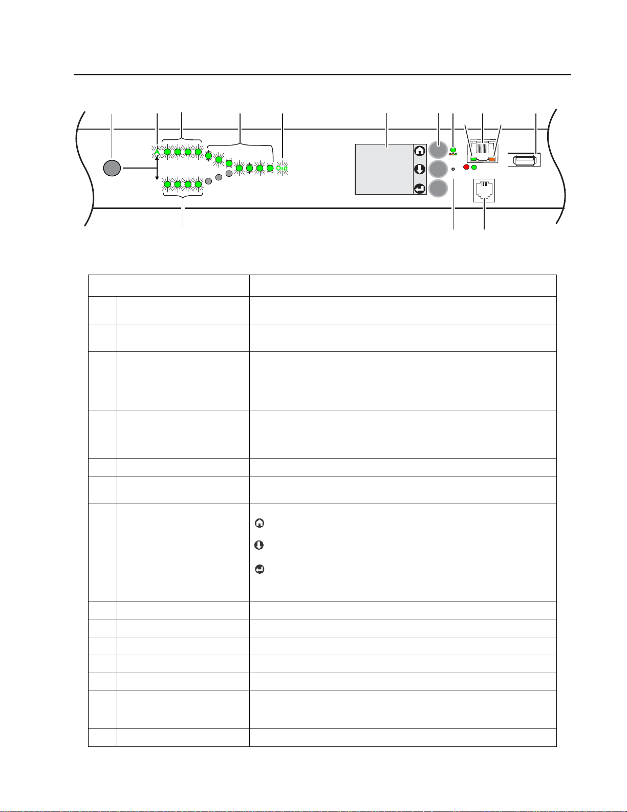
Front Panel
pdu0733b
- Warni ng
- OK
- Overload
Seri al
10/100
USB
Net wo rk
x
Reset
Preference
A/B
B
NOTE: Your Rack ATS is configured so the display back light turns off after 10 minutes of inactivity.
Press any display navigation button to illuminate the back light.
Item Function
Preference A/B Button Press to set a preferred source: the first press sets source A, the second
Source A and B LEDs Indicate preferred source. If no source is preferred, both LEDs are
Input Connector LEDs Provide information about input voltage from each source. If the RMS
Output Connector LEDs Indicate which source is being used for the output (only one path will be
Output LED Shows that voltage is available at the output of the ATS.
LCD Display View ATS status, settings, and product information. See “LCD Display
Display navigation buttons On the LCD Display, icons indicate the purpose of adjacent buttons.
press sets source B, and the third press sets no preference.
illuminated. You can also see preferred source on the LCD Display.
input voltage and measured frequency are within the selected tolerance
range, the corresponding indicator will be illuminated. In a normal
operating condition (full source redundancy) both sets of LEDs are
illuminated.
illuminated at any time). Together, the Source Preference LEDs, the
Connector LEDs, and the Output LED show the power flow through the
ATS.
Screens” on page 13 for more information on LCD display screens.
Home: Press to move through default screens or return to default
screens from menu screens.
Down: Press to move through default screens, menu items, or menu
screens.
Select: Press to navigate to the main menu from default screens,
select menu items, or return to the main menu from menu screens.
See “LCD Display Screens” on page 13 for more information.
Load Status LED See “Load Status LED” on page 12
Network Status LED See “Network Status LED” on page 12
10/100 Base-T Connector Connects the ATS to the network.
10/100 Status LED See “10/100 Status LED” on page 12.
USB port Use a USB drive to upgrade the firmware or download log files.
Serial port Connect your computer to the ATS for local access to the CLI. Use the
supplied Serial Communication cable (APC by Schneider Electric part
number 940-0144A).
Reset button Restarts ATS network and serial communication.
11Rack ATS AP44xx User Manual

Load Status LED
This LED identifies overload and warning conditions for the ATS. For more information on warning
conditions, see “Configure warning thresholds” on page 85.
Condition Description
Green The Rack ATS current is below the Near Overload Warning threshold.
Yellow The Rack ATS current is above the Near Overload Warning threshold.
Red The Rack ATS current is above the Overload Alarm threshold.
Network Status LED
This LED indicates the network status.
Condition Description
Off One or more of the following situations exists:
• The Rack ATS is not receiving input power.
• The cable that connects the Rack ATS to the network is disconnected
or defective.
• The device that connects the Rack ATS to the network is off or not
operating correctly.
• The Rack ATS is connected to an unknown network.
• The Rack ATS is not operating properly. It may need to be repaired or
replaced. Contact customer support at
Flashing green The Rack ATS is receiving data packets from the network at 10 Megabits
per second (Mbps).
Flashing orange The Rack ATS is receiving data packets from the network at 100
Megabits per second (Mbps).
Solid green or orange The Rack ATS is receiving no network traffic.
www.apc.com/support.
10/100 Status LED
This LED indicates the network status of the Rack ATS.
Condition Description
Off One or more of the following situations exists:
• The Rack A TS is not receiving input power.
• The cable that connects the Rack ATS to the network is disconnected or
defective.
• The device that connects the Rack ATS to the network is disconnected or
defective.
• The device that connects the Rack ATS to the network is turned off.
• The Rack ATS is connected to an unknown network.
• The Rack ATS is not operating properly . It may need to be repaired or
replaced. Contact customer support at
Solid green The Rack ATS has valid TCP/IP settings.
Flashing green The Rack ATS does not have valid TCP/IP settings.*
Solid orange A hardware failure has been detected in the Rack ATS.
Flashing orange The Rack ATS is making BOOTP requests.
Flashing orange and green
(alternating)
*If you do not use a BOOTP or DHCP server, see “TCP/IP Configuration Methods” on page 6 for more
options.
The Rack ATS is making DHCP requests.
www.apc.com/support.
Rack ATS AP44xx User Manual12
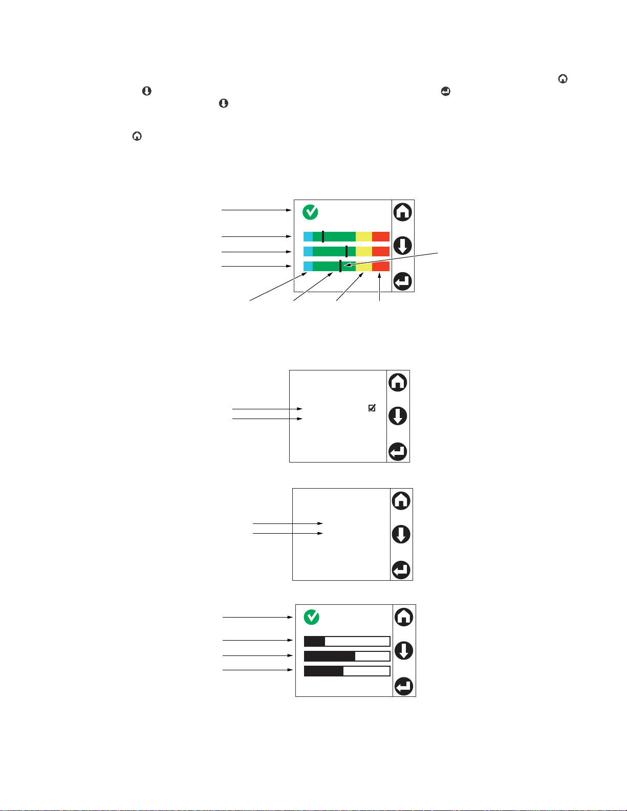
LCD Display Screens
pdu0589b
Preferred Source
Source A
Source B
None
Source Status
A: 118 V, 60 HZ
B: 118 V, 60 HZ
1
2
T
Total: 10.1A
1
2
T
Total: 10.1A
Alarm status and
total load in Amps
Bank 1 load
Bank 2 load
Total load
Blue = low load
warning range
(only visible if
configured)
Green =
normal
range
Yellow =
near
overload
range
Red =
overload
range
Black line =
load
Primary source
Secondary source
Primary source
Secondary source
Alarm status and
total load in Amps
Bank 1 load
Bank 2 load
Total load
The front panel LCD Display automatically rotate s between four default screens. You can press Home
or Down to move through these screens manually. You can press Select to go to the main menu or
select menu items. Down allows you to move through menu items and menu screens.
After 30 seconds without activity, the LCD display will revert to the default screens. You can also press
Home to return to the default screens.
Default screens
NOTE: The number of banks varies by model.
13Rack ATS AP44xx User Manual
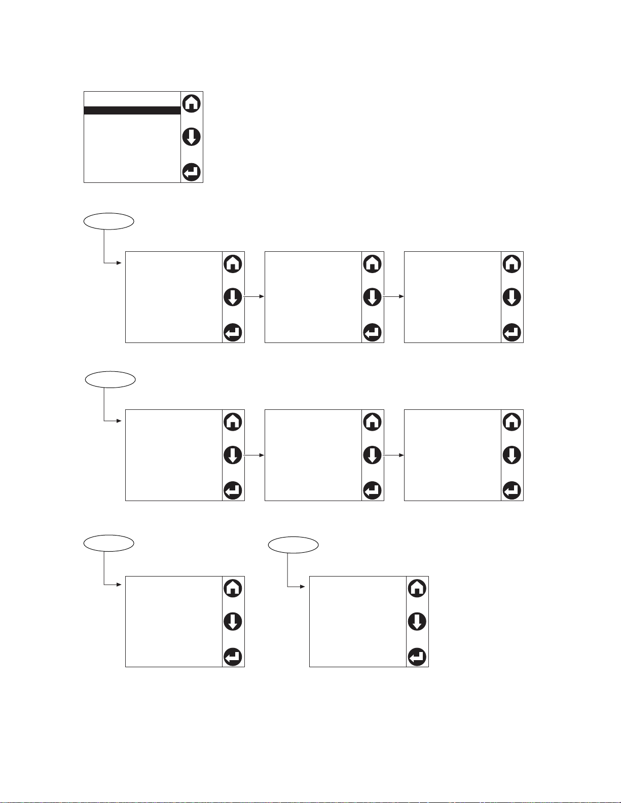
pdu0589b
Feed Info
Network
Software Info
SKU/Serial #
Alarm Status
Log to Flash
Feed A (Preferred)o
Selected
118 V, 60 Hz
10.1 A, 0.0 KvA
Feed B (Secondary)o
Available
118 V, 60 Hz
Preferred Source
Source A
Source B
None
IPv4 Addresso
Acquiring DHCP
IPv4 Addresso
FA90::2C1:B7EF:
FEDC:43AF
MAC Address
00 C0 B7 DD 42 AF
Software Info
AOS: v6.8.0
APP: v6.8.0
ATS Controller 4.2.3
SKU Information
Model Number
AP4450
Serial Number
5B1814R56718
Feed Info
Network
Software info
SKU/Serial#
Main menu
View the IPv4 Address, the IPv6 Address, or the MAC Address.
View the current software
version for each firmware
module.
View the model and serial
number for your ATS.
View information for each power source (Feed A and Feed B), or view the
Preferred Source (in green text).
Menu screens
Rack ATS AP44xx User Manual14
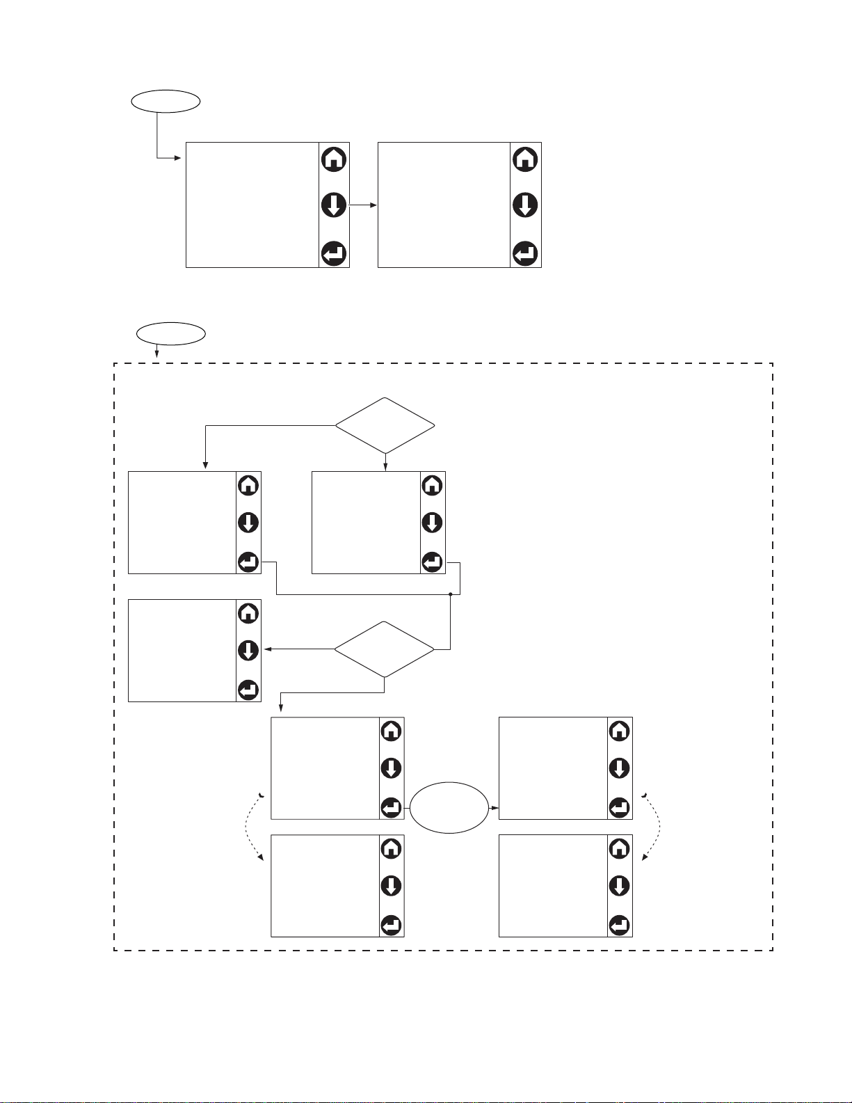
pdu0589c
Alarm Statuso
No Alarms Present
Alarm Status
No Alarms Present
Alarm Status
Log to Flash
Log to Flash
Press “Select” to start
Completed
Logs export
completed
Log to Flash
Press “Select” to start
No previous records
Log to Flash
Press “Select” to
Abort
12% Completed
Exporting Logs
Log to Flash
Press “Select” to start
Failed
No USB Detected
Log to Flash
Press “Select” to
Abort
Aborting . . .
Please wait
Log to Flash
Press “Select” to Start
Aborted
Logs export aborted
Log to Flash
Press “Select” to start
Completed
Logs export
completed
Idle State
Has export
recorded?
USB Flash
detected?
Press
“Select”
to Abort
Export Started
Confirmation
screen
displays
automatically
on completion
Confirmation
screen
displays
automatically
on completion
View active alarms.
No
Yes
Press “Select”
No
Yes
Use a USB drive at the USB port to download compressed log files.
Extract the files on your computer to view the logs.
15Rack ATS AP44xx User Manual
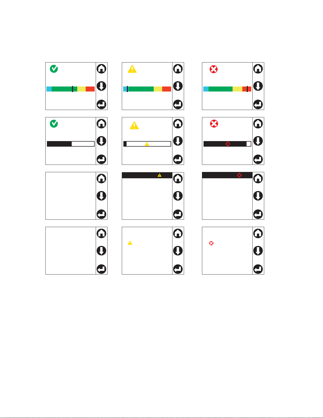
Alarm status indicators
pdu0589d
Feed A (Preferred)o
Selected
118 V, 60 Hz
10.1 A, 0.0 KvA
Alarm Statuso
No Alarms Present
Total: 10.1A
Low Load
Overload
Feed A (Preferred)o
Selected
118 V, 60 Hz
10.1 A, 0.0 KvA
Active Alarms: 1
Feed A (Preferred)o
Selected
118 V, 60 Hz
10.1 A, 0.0 KvA
Active Alarms: 1
Total: 10.1A
Low Load
Overload
Alarm Statuso
1 Warning Alarm
Alarm Statuso
1 Critical Alarm
No Alarm screens Warning Alarm (Low Load
and Near Overload)
Critical Alarm
(Overload) screens
When an alarm is generated, alarm status indicators show the level of the alarm (Warning or Critical).
Rack ATS AP44xx User Manual16

Command Line Interface
Y ou can use the Co mmand Line Interface (CLI) to configur e, manage, and monitor the st atus of the Rack
ATS. Additionally, the CLI enables you to create scripts for automated operation. You can configure all
parameters of a Rack ATS (including those for which there are not specific CLI commands) by using the
CLI to transfer an INI file to the Rack ATS. The CLI uses XMODEM to perfor m the transfer. However, you
cannot read the current INI file through XMODEM.
Log on to the CLI
To access the CLI, you can use either a local (serial) connection or a remote (Telnet or SSH) connection
with a computer on the same network as the Rack ATS.
Local access to the CLI
For local access, use a computer that connects to the Rack ATS through the serial port to access the
CLI:
1. Select a serial port at the computer and disable any service that uses that port.
2. Connect the serial communication cable (940-0144A) from the selected serial port on the
computer to the Serial port on the Rack ATS.
3. Run a terminal program (e.g., HyperTerminal) and configure the selected port for 9600 bps, 8
data bits, no parity, 1 stop bit, and no flow control.
4. Press
ENTER. At the prompts, enter your user name and password (by default, apc and apc for
the Super User). If this is your first log on, you will be prompted to change the default password.
Remote access to the CLI
You can choose to access the CLI through Telnet and/or SSH. SSH is enabled by default. You can use
the console command (see “console” on page 31) to enable or disable either Telnet or SSH. If needed,
you can also use the Web UI (see “Configure CLI access” on page 101) to enable or disable Telnet or
SSH.
Telnet for basic access
Telnet provides the basic security measure of authentication by user name and password, but not the
high-security benefits of encryption. Telnet is disabled by default.
To use Telnet to access the CLI:
1. At a command prompt, type telnet and the IP address for the Rack ATS (for example, telnet
139.225.6.133, when the Rack ATS uses the defa ult Telnet port of 23), and press
If the Rack ATS uses a non-default port number (from 5000 to 32768), you must include a colon
or a space, depending on your Telnet client, between the IP address (or DNS name) and the port
number. (These are commands for general usage; some clients do not allow you to specify the
port as an argument and some types of Linux might require extra commands).
2. Enter the user name and password. If you cannot remember your user name or password, see
“Recover from a Lost Password” on page 10.
SSH for high-security access
If you use the high security of SSL/TLS for the Web UI, use SSH for access to the CLI. SSH encrypts
user names, passwords, and transmitted data. The interface, user accounts, and user access rights are
the same whether you access the CLI through SSH or Telnet, but to use SSH, you must first configure
SSH and have an SSH client program installed on your computer. See the Security Handbook on
www.apc.com for more information on configuring and using SSH. SSH is enabled by default.
ENTER.
17Rack ATS AP44xx User Manual

About the Main Screen
Schneider Electric Network Management Card AOS vx.x.x
(c) Copyright 2019 All Rights Reserved ATS 4g APP vx.x.x
-------------------------------------------------------------------------------------Name : Test Lab Date : 8/5/19
Contact : Don Adams Time : 5:58:30
Location : Building 3 User : Administrator
Up Time : 0 Days 21 Hours 21 Minutes Stat : P+ N4+ N6+ A+
-------------------------------------------------------------------------------------IPv4 : Enabled IPv6 : Enabled
Ping response : Enabled
--------------------------------------------------------------------------------------
HTTP : Disabled HTTPS : Enabled
FTP : Disabled Telnet : Disabled
SSH/SCP
: Enabled SNMPv1 : Disabled
SNMPv3 : Disabled
--------------------------------------------------------------------------------------
Super User : Enabled RADIUS : Disabled
Administrator : Disabled Device User : Disabled
Read-only User : Disabled Network-Only User : Disabled
Type ? For command listing
Use tcpip for IP address (-i), subnet (-s), and gateway (-g)
apc>
The following screen is displayed when you log on to the CLI of a Rack ATS.
• Two fields identify the operating system (AOS) and application (APP) firmware versions. The
application firmware name identifies the type of device that connects to the network (for example,
a Rack ATS).
Network Management Card AOS vx.x.x
ATS4g APP vx.x.x
• Three fields identify the system name, contact person, and location of the Rack ATS.
Name : Test Lab
Contact : Don Ad ams
Location : Building 3
• An Up Time field reports how long the Rack ATS Management Interface has been running since it
was last turned on or reset.
Up Time: 0 Days, 21 Hours, 21 Minutes
Rack ATS AP44xx User Manual18

• Two fields identify when you logged in, by date and time.
Date: 11/2/2019
Time: 09:06:45
• The
User field identifies whether you logged in through the Super User, Administrator, Device
User, Read-Only, or Network-Only account.
User: Administrator
• A
Stat field reports the Rack ATS status.
Stat:P+ N4+ N6+ A+
P+
IPv4
only
The APC operating system (AOS) is functioning properly.
IPv6
only
IPv4 and
IPv6* Description
N+ N+ N4+ N6+ The network is functioning properly.
N? N6? N4? N6? A BOOTP request cycle is in progress.
N– N6- N4- N6- The Rack ATS failed to connect to the network.
N! N6! N4! N6! Another device is using the Rack ATS IP address.
* The
N4 and N6 values can be different from one another: you could, for example, have
N4- N6+.
A+
The application is functioning properly.
A– The application has a bad checksum.
A? The application is initializing.
A! The application is not compatible with the AOS.
NOTE: If P+ is not displayed, contact the APC by Schneider Electric Customer Care Center at
www.apc.com/support.
• The remaining fields show which protocols and user accounts are enabled.
Using the CLI
At the CLI, you can use commands to configure the Rack ATS. To use a command, type the command
and press
are case-sensitive.
ENTER. Commands and arguments are valid in lowercase, upperca se, or mixed case. Options
While using the CLI, you can also do the following:
• Type help or ? and press
ENTER to view a list of available commands, based on your account
type.
• To obtain information about the purpose and syntax of a specified command, type the command,
a space, and ? or the word help.
• Press the
the
UP arrow key to view the command that was entered most recently in th e session. Use
UP and DOWN arrow keys to scroll through a list of up to ten previous commands.
• Type at least one letter of a command and press the TAB key to scroll through a list of valid
commands that match the text you have typed in the command line.
• Type bye, exit or quit to close the connection to the CLI.
19Rack ATS AP44xx User Manual

Command Syntax
Item Description
- Options are preceded by a hyphen.
< > Definitions of options are enclosed in angle brackets.
For example:
[ ] If a command accepts multiple options or an option accepts mutually exclusive arguments, the values
may be enclosed in brackets.
| A vertical line between items enclosed in brackets or angle brackets indicates that the items are
mutually exclusive. You must use one of the items.
Example of a command that supports multiple options:
ftp [-p <port number>] [-S <enable | disable>]
In this example, the ftp command accepts the option -p, which defines the port number , a nd the option
-S, which enables or disables the FTP feature.
To change the FTP port number to 5010, and enable FTP:
1. Enter the ftp command, the port option, and the argument 5010:
ftp -p 5010
2. After the first command succeeds, enter the ftp command, the enable/disable option, and the
enable selection:
ftp -S enable
Example of a command that accepts mutually exclusive arguments for an option:
-dp <device password>
alarmcount -p [all | warning | critical]
In this example, the option -p accepts only three argumen ts: all, warning, or critical. For example,
to view the number of active critical alarms, type:
alarmcount -p critical
The command will fail if you type an argument that is not specified.
Rack ATS AP44xx User Manual20

Command Response Codes
The command response codes enable scripted operations to detect error conditions reliably without
having to match error message text:
The CLI reports all command operations with the following format:
E [0-9] [0-9] [0-9] : Error message
Code Message
E000 Success
E001 Successfully Issued
E002 Reboot required for change to take effect
E100 Command failed
E101 Command not found
E102 Parameter Error
E103 Command Line Error
E104 User Level Denial
E105 Command Prefill
E106 Data Not Available
E107 Serial Communications Lost
E108 EAPoL disabled due to invalid/encrypted certificate.
E200 Input error. Only reported when an error occurs during the execution of a command.
E201 No Response. Reported when a sensor fails to respond.
E202 Invalid value
E203 Device busy or lost communication. Please try again.
Reported when there is any problem with the arguments supplied to the command:
too few, too many, wrong type, etc.
Prompting for User Input during Command Execution
Certain commands require additional user input (ex. transfer .ini prompting for baud rate). There is a
fixed timeout of 1 minute for such prompts. Should the user not enter any text within the timeout period,
then the command will print "E100: Command Failed.” and the command prompt will be redisplayed.
21Rack ATS AP44xx User Manual

Command Editing
The <backspace> key will delete the last character of the command string the user is currently entering
and is the only editing function available to the user during command entry.
History
The Rack A TS CLI implements a command history buf fer , recalling the 10 previous commands. The user
can navigate backwards and forwards through entered commands using the <up arrow> and <down
arrow> keys respectively.
Auto Completion
The Rack A TS CLI support s command auto-completion. If a p artial command is entered, then th e <TAB>
key can be used to complete the command to the first available matched command. If such a match
exists, the command line shall be completed by the system.
Additional presses of the <TAB> key will select the next available command match. Once all available
commands have been scrolled through, the original partially entered command is displayed.
Delimiter
The Rack ATS CLI will use <space> (ASCII 0x20) as the delimiter between commands and arguments.
Extra white space between commands and arguments will be ignored.
Command responses will have all fields delimited with commas for efficient parsing.
Rack ATS AP44xx User Manual22

Options and Arguments Inputs
Entering a command with no options or a rgume nts returns the current value of all options available from
that command.
Entering the command and an option with no argument s returns the current value of that option only. Any
command followed by a question mark "?" returns help explaining the command.
<space> ::= (" " | multiple" ")
<valid letter_number> ::= (a-z | A-Z | 0-9)
<string> ::= (1 - 64 consecutive printable valid ASCII characters
[ranging from hex 0x20 to 0x7E inclusive] )
NOTE: If the string includes a blank, the entire string MUST be surrounded by quotes(" ").
<option> ::= "-"(<valid letter_number> | <valid letter_number><valid
letter_number>)
<argument> ::=
<helpArg> | <alarmcountArg> | <bootArg> | <cdArg> | <consoleArg> |
<dateArg> | <deleteArg> | <ftpArg> | <pingArg> | <portspeedArg> |
<promptArg> | <radiusArg> | <resettodefArg> | <systemArg> |
<tcpipArg> | <userArg> | <webArg> | <string>
<optionArg> ::= <option><argument>
Command Console and CLI Response Format
All CLI commands will issue:
<three digit response code>:<space> (followed by a readable text (response message))
This can be followed by <cr><lf> and the output of the command (if applicable).
Response Format and Message Codes
Successful command operations will have an error code less than 100. Any error code of 100 or greater ,
indicates a failure of some type.
E[0-9][0-9][0-9]: Error message
See “Command Response Codes” on page 21 for more information.
Example:
E000: Success (followed by the output of the command, if applicable)
23Rack ATS AP44xx User Manual

Rack ATS System Command Descriptions
? or help
Access: Super User, Administrator, Device User, Read Only, Network Only
Description: View a list of all the CLI commands available to your account type, or view help text for a
specific command.
Parameters: [<command>]
Example 1:
apc> ?
System Commands:
----------------------------------------------------------------------For command help: command ?
? about alarmcount boot bye cd
cipher clrrst console date delete dir
dns email eventlog exit firewall format
ftp help lang lastrst ledblink logzip
netstat ntp ping portspeed prompt pwd
quit radius reboot resetToDef session smtp
snmp snmptrap snmpv3 system tcpip tctpip6
user userdflt web whoami xferINI xferStatus
Device Commands:
--------------------------------------------------------------------------aboutATS atsMeasure atsStatus bkLowLoad bkNearOver bkOverLoad
bkPeakLoad bkReading freqDeviat eventCounts frontPanel lcd
lcdBlink lineVRMS prodInfo sourceAName sourceBName sourcePref
vMediumLmt vNarrowLmt vSensitvty vWideLmt vXferRange
Example 2:
apc> boot help
Usage: boot -- Configuration Options
boot [-b <dhcp | Bootp | manual>] (IPv4 Boot Mode)
[-c <enable | disable>] (Require DHCP Cookie)
[-v <vendor class>]
[-i <client id>]
[-u <user class>]
Error Message: E000, E102
Rack ATS AP44xx User Manual24

about
Access: Super User, Administrator, Device User, Read Only
Description: Displays system information (Model Number, Serial Number, Manufacture Dates, etc.)
Parameters: None
Example:
apc> about
E000: Success
Hardware Factory
--------------Model Number: AP44XX
Serial Number: ST181313012345
Hardware Revision: R05
Manufacture Date: 05/06/19
MAC Address: 00 C0 B7 18 00 01
Management Uptime: 0 Days 1 Hour 42 Minutes
Network Management Card
--------------Model Number: AP9538
Serial Number: ZA1821008486
Hardware Revision: 05
Manufacture Date: 5/11/2019
Application Module
--------------Name: ats4g
Version: v6.8.0
Date: Aug 3 2019
Time: 18:46:52
APC OS(AOS)
--------------Name: aos
Version: v6.8.2
Date: Aug 3 2019
Time: 16:00:07
APC Boot Monitor
--------------Name: bootmon
Version: v1.0.8
Date: Apr 8 2014
Time: 10:59:40
Error Message: E000
25Rack ATS AP44xx User Manual

alarmcount
Access: Super User, Administrator, Device User, Read Only
Description: Displays alarms present in the system. Information about the alarms is provided in the
event log.
Parameters:
Option Argument Description
-p all View the total number of active alarms reported by the Rack ATS.
warning View the number of any kind of active alarm reported by the Rack ATS.
critical
informational
Example: To view all active warning alarms, type:
apc> alarmcount -p warning
E000: Success
WarningAlarmCount: 3
apc> alarmcount -p all
E000: Success
AlarmCount: 7
Error Message: E000, E102
Rack ATS AP44xx User Manual26

boot
Access: Super User, Administrator
Description: Allows the user to get/set the network startup configuration of the device, such as setting
boot mode.
Parameters:
Option Argument Description
-b <dhcp | bootp | manual> Define how the TCP/IP settings will be configured when the
Rack ATS turns on, reset s, or restarts. See “Configure TCP/IP
and communication settings for IPv4 and IPv6” on page 96 for
information about each boot mode setting.
-c <enable | disable> dhcp boot mode only: Enable or disable the requirement that
the DHCP server provide the APC cookie.
-v <vendor class> dhcp boot mode only: the Vendor Class is APC.
-i <client id> dhcp boot mode only: the MAC address of the NMC, Which
-u <user class> dhcp boot mode only: the name of the application firmware
Example: Using a DHCP server to obtain network settings:
apc> boot
E000: Success
Boot Mode: manual
Non-Manual Mode Shared Settings
------------------------------Vendor class: <device class>
Client id: XX XX XX XX XX XX
User class: <user class>
After IP assignment: gotoDhcpOrBootp
uniquely identifies it on the network.
module.
DHCP Settings
------------Retry then stop: 4
DHCP cookie is: enable
BOOTP Settings
-------------Retry then fail: never
On retry failure: prevSettings
Error Message: E000, E102
27Rack ATS AP44xx User Manual

bye, exit, or quit
Access: Super User, Administrator, Device User, Read Only, Network-Only User
Description: Exit from the CLI session.
Parameters: None
Example:
apc> exit
Bye
Error Message: None
cd
Access: Super User, Administrator, Device User, Read Only
Description: Allows the user to set the working directory of the file system. The working directory is set
back to the root directory ‘/’ when the user logs out of the CLI.
Parameters: <directory name>
Example:
apc> cd logs
E000: Success
apc> cd /
E000: Success
Error Message: E000, E102
Rack ATS AP44xx User Manual28

cipher
Access: Super User, Administrator
Description: Enable or disable cryptographic algorithms for Web UI sessions. You cannot enable or
disable these algorithms directly from the Web interface. You must reboot your NMC after enabling or
disabling algorithms for changes to take effect.
There are three categories of algorithms: Authentication Algorithms, Block Cipher Algorithms, and MAC
Algorithms. Available and Blocked Cipher Suites are also listed.
NOTE: Disabling the only algorithm in a category will block all SSL/TLS sessions and HTTPS access
may not work depending on your browser and its configuration.
NOTE: In v6.7.2 and higher, you must explicitly enable or disable an algorithm.
Option Argument Description
-3des enable | disable
-aes enable | disable Enable or disable Advanced Encryption Standard (AES).
Enable or disable Triple DES.
-dh enable | disable Enable or disable Diffie-Hellman (DH).
-rsake enable | disable Enable or disable RSA key exchange.
-rsaau enable | disable Enable or disable RSA authentication.
-sha1 enable | disable Enable or disable Secure Hash Algorithm 1 (SHA-1).
-sha2 enable | disable Enable or disable Secure Hash Algorithm 2(SHA-2).
-ecdhe enable | disable Enable or disable Elliptic Curve Diffie-Hellman Exchange
(ECDHE).
Example: Disable triple-DES.
cipher -3des disable
E000: Success
Reboot required for change to take effect.
Error Message: E000, E102
29Rack ATS AP44xx User Manual

Example 2: Retrieve a list of each available cryptographic algorithm and its status.
apc> cipher
E000: Success
Key Exchange Algorithms
----------------------DH enabled
RSA Key Exchange enabled
Authentication Algorithms
-------------------------
(Warning: disabling the only algorithm in category
will block all SSL/TLS sessions)
RSA Authentication enabled
Block Cipher Algorithms
----------------------triple-DES enabled
RC4 enabled
AES enabled
MAC Algorithms
-------------MD5 enabled
SHA enabled
SHA256 enabled
Available Cipher Suites
-----------------------
1 TLS_DHE_RSA_WITH_3DES_EDE_CBC_SHA
2 TLS_DHE_RSA_WITH_AES_128_CBC_SHA
3 TLS_DHE_RSA_WITH_AES_128_CBC_SHA256
4 TLS_DHE_RSA_WITH_AES_256_CBC_SHA
5 TLS_DHE_RSA_WITH_AES_256_CBC_SHA256
6 SSL_RSA_WITH_3DES_EDE_CBC_SHA
7 TLS_RSA_WITH_AES_128_CBC_SHA
8 TLS_RSA_WITH_AES_256_CBC_SHA
9 TLS_RSA_WITH_AES_128_CBC_SHA256
10 TLS_RSA_WITH_AES_256_CBC_SHA256
11 SSL_RSA_WITH_RC4_128_SHA
12 SSL_RSA_WITH_RC4_128_MD5
13 SSL_RSA_EXPORT_WITH_RC4_40_MD5
Blocked Cipher Suites
---------------------
None
Error Message: E000, E102
Rack ATS AP44xx User Manual30

clrrst
Access: Super User, Administrator, Device User
Description:
Clear reset reason.
Parameters: None
Example: None
Error Message: None
console
Access: Super User, Administrator
Description: Define whether users can access the CLI using Telnet, which is disabled by default, or
Secure SHell (SSH), which is enabled by default and provides protection by transmitting user names,
passwords, and data in encrypted form. You can change the Telnet or SSH port setting for additional
security. Alternately, disable network access to the CLI.
Parameters:
Option Argument Description
-s <enable | disable> Enable or disable SSH access to the device. Enabling SSH
-t <enable | disable> Enable or disable Telnet access to the device.
-pt <telnet port> Define the Telnet port used to communicate with the Rack ATS
-ps <SSH port> Define the SSH port used to communicate with the Rack ATS
-b <2400 | 9600 | 19200 |
38400>
enables SCP.
(23 by default, optional 5000–32768).
(22 by default, optional 5000–32768).
Configure the speed of the serial port connection (serial baud
rate) in bits per second (bps). The default is 9600 bps.
Example 1: To enable SSH access to the CLI:
apc> console -s enable
E000: Success
SSH: enabled
Example 2: To view the serial baud rate:
apc> console -b
E000: Success
Baud Rate: 9600
Error Message:E100, E102
31Rack ATS AP44xx User Manual

date
Access: Super User, Administrator
Description: Get and set the date and time of the system. To configure an NTP server to define the
date and time for the Rack ATS, see “Configure date, time, and daylight savings” on page 113.
Parameters:
Option Argument Description
-d <“datestring”> Set the current date. The format must match the current -f setting.
-t <00:00:00> Configure the current time, in hours, minutes, and seconds. Use the 24-hour
-f <mm/dd/yy|
dd.mm.yyyy|
mmm-dd-yy|
dd-mmm-yy|
yyyy-mm-dd>
-z <time zone
offset>
Example 1: To display the date:
apc> date
E000: Success
Date: 11/02/2019
Time: 09:06:45
Format: mm/dd/yyyy
Time Zone: -05:00
clock format.
Select the numerical format in which to display all dates in this user interface.
Each letter m (for month), d (for day), and y (for year) represents one digit.
Single-digit days and months are displayed with a leading zero.
Set the difference with GMT in order to specify your time zone. This enables
you to synchronize with other people in different time zones.
Example 2: To define the date as November 3, 2019 using the yyyy/mm/dd format:
date -d “2019/11/03”
Example 3: To define the time as 5:21:03 p.m., type:
date -t 05:21:03
Error Message: E000, E100, E102
delete
Access: Super User, Administrator
Description: Delete a file in the file system.
Parameters:
Argument Description
<file name> Type the name of the file to delete.
Example:
apc> delete /db/prefs.dat
E000: Success
Error Messages: E000, E102
Rack ATS AP44xx User Manual32

dir
Access: Super User, Administrator, Device User, Read Only
Description: Displays the content of the working directory.
Parameters
Argument Description
<all | dir | name> Show the contents of the current (or specified) directory.
Example:
apc> dir
E000: Success
2978816 Aug 3 17:46 apc_hw05_aos_682.bin
1803460 Sep 19 17:44 apc_hw05_ats4g_680.bin
45000 Nov 2 7:45 config.ini
0 Oct 31 14:04 db/
0 Oct 31 14:04 ssl/
0 Oct 31 14:04 ssh/
0 Oct 31 14:04 logs/
0 Oct 31 14:04 sec/
0 Oct 31 14:04 dbg/
0 Oct 31 14:04 fwl/
0 Oct 31 14:04 email/
0 Oct 31 14:04 lang/
0 Oct 31 14:04 rms/
Error Messages: E000
33Rack ATS AP44xx User Manual

dns
Access: Super User, Administrator
Description: Configure the manual Domain Name System (DNS) settings.
Parameters
Option Argument Description
-OM <enable | disable> Override the ma nual DNS.
-p <primary DNS server> Set the primary DNS server.
-s <secondary DNS server> Set the secondary DNS server.
-d <domain name> Set the domain name.
-n <domain name IPv6> Set the domain name IPv6.
-h <host name> Set the host name.
-y <enable | disable> System-host name sync
Example:
apc> dns
E000: Success
Active Primary DNS Server: x.x.x.x
Active Secondary DNS Server: x.x.x.x
Override Manual DNS Settings: enabled
Primary DNS Server: x.x.x.x
Secondary DNS Server: x.x.x.x
Domain Name: example.com
Domain Name IPv6: example.com
System Name Sync: Enabled
Host Name: ExampleHostName
Error Message: E000, E102
Rack ATS AP44xx User Manual34

eapol
Access: Super User, Administrator, User
Description: Configure EAPoL (802.1X Security) settings.
Parameters:
Option Argument Definition
-S <enable | disable>
Enable or disable EAPoL.
-n <supplicant name> Set the supplicant name.
-p
<private key passphrase>
Set the private key passphrase.
Example 1: To display the result of an eapol command:
apc>eapol
E000: Success
Active EAPoL Settings
------------------- Status:enabled
Supplicant Name:NMC-Supplicant
Passphrase:<hidden>
CA file Status:Valid Certificate
Private Key Status:Valid Certificate
Public Key Status:Valid Certificate
Result:Success
Example 2: To enable EAPoL:
apc>eapol -S enable
E002: Success
Reboot required for change to take effect.
Example 3: To change the supplicant name:
apc>eapol -n "NMC-Supplicant"
E000: Success
Example 4: To set the passphrase:
apc>eapol -p "client_password"
E000: Success
35Rack ATS AP44xx User Manual

Access: Super User, Administrator, Device User
Description: View email
Parameters:
Option Argument Description
-g[n] <enable | disable> Enable/disable generation.
-t[n] <To Address> Set the To address.
-o[n] <long | short> Set the format (long or short).
-l[n] <Language Code> Set the language code; this should be
-r[n] <Local | recipient | custom> Set the route (local, recipient, or custom).
Custom Route Option
-f[n] <From Address> Set the From address.
-s{n} <SMTP Server> Set the smtp server address.
-p[n] <Port> Set the port.
-a[n] <enable | disable> Enable/disable authentication.
-u[n] <User Name> Set the user name.
-w[n] <Password> Set the password.
-e[n] <none | ifsupported | always |
implicit>
-c[n] <enable | disable > Enable/disable the requiring of certificates.
-i[n] <Certificate File Name> Set the certificate file name.
n = Email Recipient Number (1,2,3 or 4)
supported by current language pack.
Set the encryption.
Example:
apc> email
E000: Success
Recipient: 1
Generation: enabled
Address: example@example.com
Format: long
Language: enUs - English
Route: local
Error Message: E000, E102
Rack ATS AP44xx User Manual36

eventlog
Access: Super User, Administrator, Device User, Read Only
Description: View the date and time you retrieved the event log, the status of the Rack ATS, and the
status of sensors connected to the Rack ATS. View the most recent device events and the date and time
they occurred. Use the following keys to navigate the event log:
Key Description
E
SC Close the event log and return to the CLI.
E
NTER Update the log display. Use this command to view events that were recorded after you last
retrieved and displayed the log.
S
PACEBAR View the next page of the event log.
B View the preceding page of the event log. This command is not available at the main page of
the event log.
D Delete the event log. Follow the prompts to confirm or deny the deletion. Deleted events cannot
be retrieved.
Example:
apc> eventlog
---- Event Log ---------------------------------------------------- Date: 11/02/2019 Time: 09:06:45
----------------------------------- Automatic Transfer Switch: Source B selected, Switchover Possible
Date Time User Event
-------------------------------------------------------------- 11/02/2019 07:17:22 apc CLI user ‘apc’ logged in from
10.218.116.179
11/02/2019 12:16:57 apc CLI user ‘apc’ logged outfrom
10.218.116.179
11/01/2019 13:16:49 apc CLI user ‘apc’ logged in from
10.218.116.179
11/03/2019 14:16:35 apc CLI user ‘apc’ logged out from
10.218.116.179
10/28/2019 13:15:30 System CLI user ‘apc’ logged out from
serial port.
10/28/2019 13:15:00 ATS Automatic Transfer Switch: Voltage
Transfer Range Configuration change.
<ESC>- Exit, <ENTER>- Refresh, <SPACE>- Next, <D>- Delete
Error Message: E000, E100
exit
See “bye, exit, or quit” on page 28.
37Rack ATS AP44xx User Manual

firewall
Access: Super User, Administrator
Description: Establishes a barrier between a trusted, secure internal network and another network.
Parameters:
Option Argument Description
-S <enable | disable> Enable or disable the Firewall.
-f <file name to activate> Name of the firewall to activate.
-t <file name to test>
<duration time in minutes>
-fe No argument. List only Shows active file errors.
-te No argument. List only Shows test file errors.
-c No argument. List only Cancel a firewall test.
-r No argument. List only Shows active firewall rules.
-l No argument. List only Shows firewall activity log.
-Y No argument. Skip firewall test prompt.
Example 1:
apc> firewall -S enable
Firewall should be tested with “firewall -t example.fwl” before
enabling it. Are you sure you want to enable it now?
Enter ‘YES’ to continue or <ENTER> to cancel : YES
E000: Success
Name of firewall to test and
duration time in minutes.
Example 2:
apc> firewall -S enable -Y
E000: Success
Error Message: E000, E100, E102
format
Access: Super User, Administrator
Description: Allows the user to format the FLASH file system. This will delete all configuration data
(including network settings), event and data logs, certificates and keys, and reset the card to the factory
defaults. See “resetToDef” on page 45.
Parameters: None
Example:
apc> format
Format FLASH file system
Warning: This will delete all configuration data,
event and data logs, certs and keys.
Enter 'YES' to continue or <ENTER> to cancel:
apc> YES
Error Message: None
Rack ATS AP44xx User Manual38

ftp
Access: Super User, Administrator
Description: Get/set the FTP configuration data,
NOTE: The system will reboot if any configuration is changed.
Parameters:
Option Argument Description
-p <port number> Define the TCP/IP port that the FTP server uses to communicate with
the Rack ATS (21 by default). The FTP server uses both the specified
port and the port one number lower than the specified port. Valid
values are 21 and 5000-32768.
-S <enable | disable> Configure access to the FTP server.
Example: To change the TCP/IP port:
apc> ftp -p 5001
E000: Success
Reboot required for change to take effect.
apc> ftp
E000: Success
Service: Enabled
Ftp Port: 5001
apc> ftp -p 21
E000: Success
Reboot required for change to take effect
Error Message: E000, E102
help
See “? or help” on page 24.
lang
Access: Super User, Administrator, Device User, Read Only
Description: Displays the language in use.
Parameters: None
Example:
apc> lang
E000: Success
Languages
enUs - English
Error Message: None
39Rack ATS AP44xx User Manual

lastrst
Access: Super User, Administrator, Device User
Description: Last reset reason
Parameters: None
Example:
apc> lastrst
04 Requested Reset
E000: Success
Error Message: None
ledblink
Access: Super User, Administrator, Device User
Description: Sets the LED on the Rack ATS to blink.
Parameters:
Argument Description
<duration time in minutes> Set the number of minutes for the LED to blink.
Example:
apc> ledblink 2
E000 Success
Error Message: None
logzip
Access: Super User, Administrator, Device User
Description: Places large logs into a zip file before sending.
Parameters:
Option Argument Description
-m <email recipient> Email recipient number (1-4)
Example:
apc> logzip -m 1
Generating files
Compressing files into /dbg/debug_ZA1023006009.tar
E000: Success
Error Message: E000
Rack ATS AP44xx User Manual40

netstat
Access: Super User, Administrator, Device User, Read Only
Description: Displays incoming and outgoing network connections.
Parameters: None
Example:
apc> netstat
Current IP Information:
Family mHome Type IPAddress Status
IPv6 4 auto FE80::2C0:B7FF:FE51:F304/64 configured
IPv4 0 dhcp 10.218.117.43/24 configured
IPv6 0 manual ::1/128 configured
IPv4 0 manual 127.0.0.1/32 configured
Error Message: E000, E102
ntp
Access: Super User, Administrator
Description: Synchronizes the time of a computer client or server.
Parameters
Option Argument Description
-OM <enable | disable> Override the manual settings.
-p <primary NTP server> Specify the primary server.
-s <secondary NTP
server>
Example 1: To enable the override of manual setting, type:
apc> ntp -OM enable
E000: Success
NTP status: Enabled
Example 2: To specify the primary NTP server, type:
apc> ntp -p 150.250.6.10
E000: Success
Primary NTP Server: 150.250.6.10
Error Message: E000, E102
Specify the secondary server.
41Rack ATS AP44xx User Manual

ping
Access: Super User, Administrator, Device User
Description Perform a network ‘ping’ to any external network device.
Parameters
Argument Description
<IP address or DNS name> Type an IP address with the format xxx.xxx.xxx.xxx, or the DNS name
configured by the DNS server.
Example:
apc> ping 192.168.1.50
E000: Success
Reply from 192.168.1.50: time(ms)= <10
Reply from 192.168.1.50: time(ms)= <10
Reply from 192.168.1.50: time(ms)= <10
Reply from 192.168.1.50: time(ms)= <10
Error Message: E000, E100, E102
portSpeed
Access: Super User, Administrator
Description: Allows the user to get/set the network port speed.
NOTE: The system will reboot if any configuration is changed.
Parameters
Option Argument Description
-s <auto | 10H | 10F
| 100H | 100F>
H = Half Duplex
F = Full Duplex
Define the communication speed of the Ethernet port. The auto
command enables the Ethernet devices to negotiate to transmit at the
highest possible speed. See “Configure network port speed” on
page 98 for more information about the port sp eed settings.
10 = 10 Meg Bits
100 = 100 Meg Bits
Example:
apc> portspeed
E000: Success
Port Speed: Auto_negotiation
Current Port Speed: 100 Full_Duplex
Error Message: E000, E102
Rack ATS AP44xx User Manual42

prompt
Access: Super User, Administrator, Device User
Description: Change the format of the prompt, either short or long
Parameters
Option Argument Description
-s long The prompt includes the account type of the currently logged-in user.
short The default setting. The prompt is four characters long: APC>
Example:
apc> prompt –s long
E000: Success
apc@apc> prompt -s short
E000: Success
apc>_
Error Message: E000, E102
pwd
Access: Super User, Administrator, Device User, Read Only
Description: Used to output the path of the current working directory.
Parameters: None
Example:
apc> pwd
/
apc> cd logs
E000: Success
apc> pwd
/logs
Error Message: E000, E102
43Rack ATS AP44xx User Manual

radius
Access: Super User, Administrator
Description: View the existing RADIUS settings, enable or disable RADIUS authentication, and
configure basic authentication parameters for up to two RADIUS servers.
For a summary of RADIUS server configuration and a list of supported RADIUS servers, se e “ Configu re
a RADIUS server” on page 92.
Additional authentication parameters for RADIUS servers are available at the Web UI of the Rack ATS.
See “Manage remote user settings” on page 91 for more information.
For detailed information about configuring your RADIUS server, see the Security Handbook, available at
www.apc.com.
Parameters
Option Argument Description
-a <local |
radiusLocal
| radius>
-p1
<server IP> The server name or IP address of the primary or secondary RADIUS server.
-p2
-o1
-o2
-s1
-s2
-t1
-t2
<server
port>
<server
secret>
<server
timeout>
Configure RADIUS authentication:
•
local: RADIUS is disabled. Local authentication is enabled.
• radiusLocal: RADIUS, then Local Authentication. RADIUS and local
authentication are enabled. Authentication is requested from the RADIUS
server first. If the RADIUS server fails to respond, local authentication is used.
radius: RADIUS is enabled. Local authentication is disabled.
•
NOTE: RADIUS servers use port 1812 by default to authenticate users. T o use a
different port, add a colon followed by the new port number to the end of the
RADIUS server name or IP address. The Rack ATS supports port s 1812, 5000 to
32768.
The port for the primary or secondary RADIUS sever.
The shared secret between the primary or secondary RADIUS server and the
Rack ATS.
The time in seconds that the Rack ATS waits for a response from the primary or
secondary RADIUS server.
Example 1: To view the existing RADIUS settings for the Rack ATS, type radius and press
apc> radius
E000: Success
Access: Local Only
Primary Server: 0.0.0.0
Primary Server Port: 1812
Primary Server Secret: <Password Hidden>
Primary Server Timeout: 5
Secondary Server: 0.0.0.0
Secondary Server Port: 1812
Secondary Server Secret: <Password Hidden>
Secondary Server Timeout: 5
ENTER.
Error Message: E000, E102
Rack ATS AP44xx User Manual44

reboot
Access: Super User, Administrator
Description: Restart the NMC interface of the Rack A T S only. Forces the network device to reboot. User
must confirm this operation by entering a “YES” after the command has been entered.
Parameters:
Option Description
-Y Skip confirmation prompt. (Uppercase Y only.)
Example 1:
apc> reboot
E000: Success
Reboot Management Interface
Enter 'Y' to continue or <ENTER> to cancel : <user enters ‘YES’>
Rebooting...
Example 2:
apc> reboot -Y
E000: Success
Reboot Management Interface
Rebooting...
Error Message: E000, E100
resetToDef
Access: Super User, Administrator
Description: Reset all parameters to their default. Deletes all accounts and clears event and data logs.
Resets all configuration changes, including event actions, device settings, and, optionally, TCP/IP
configurations settings.
Parameters:
Option Argument Description
-p <all | keepip> • all: all configura tion data, including the IP address.
keepip: all configuration data, except the IP address.
•
Reset all configuration changes, including event actions, device settings,
and, optionally, TCP/IP configuration settings.
Example: To reset all of the configuration changes except the TCP/IP settings for the Rack ATS, type:
resetToDef -p keepip
Enter 'YES' to continue or <ENTER> to cancel : : <user enters ‘YES’>
all User Names, Passwords.
Please wait...
Please reboot system for changes to take effect!
Error Message: E000, E100
45Rack ATS AP44xx User Manual

session
Access: Super User, Administrator, Device User
Description: Records who is logged in, the serial, time and ID.
Parameters:
Option Argument Description
-d <session ID> End user session.
-m <enable | disable> Allow multiple users to be logged on at once.
-a
Example:
Error Message: E000, E102
<enable | disable> Enable or disable Serial Remote Authentication
Override, which allows users to Bypass RADIUS by
using a serial connection to the CLI.
apc> session
User Interface Address Logged In Time ID
-------------------------------------------------------------------apc Web x.x.x.x 00:00:08 156
apc Telnet x.x.x.x 00:00:02 157
E000: Success
Rack ATS AP44xx User Manual46

smtp
Access: Super User, Administrator
Description: Internet standard for electronic mai l.
Parameters:
Option Argument Description
-f <From Address> Set e-mail From address.
-s <SMTP Server> Set the SMTP server address.
-p <Port> Set e-mail recipient port number. Options
-a <enable | disable> Enable or disable authentication
-u <User Name> Set user name for authentication.
-w <Password> Set e-mail password for authentication.
-e <none | ifavail | always | implicit> Define when to use encryption.
-c <enable | disable> Enable or disable certificate requirement.
-i <Certificate File Name> Set the certificate file name.
Example:
apc> smtp
E000: Success
include 25, 2525, 465, 587, and 5000 to
32768.
From: address@example.com
Server: mail.example.com
Port: 25
Auth: disabled
User: User
Password: <not set>
Encryption: none
Req. Cert: disabled
Cert File: <n/a>
Error Message: E000, E102
47Rack ATS AP44xx User Manual

snmp
Access: Super User, Administrator
Description: Enable or disable SNMPv1. Set configuration for up to 4 Access Control groups.
NOTE: SNMPv2c uses SNMPv1 configuration settings.
Parameters:
Option Argument Description
-S <enable | disable> Enable or disable SNMPv1. SNMPv1 is
disabled by default,
-c[n] <Community> Identify the group of Rack ATS units for
access control.
-a[n] <read | write | writeplus | disable> Set the access level.
-n[n] <IP or Domain Name> Set the host’s name or address
[n] = Access Control # (1, 2, 3, or 4)
Example:
apc> snmp
E000: Success
SNMPv1: enabled
Access Control summary:
Access Control #: 1
Community: public
Access Type: read
Address: 0.0.0.0
Access Control #: 2
Community: private
Access Type: write +
Address: 0.0.0.0
Access Control #: 3
Community: public2
Access Type: disabled
Address: 0.0.0.0
Access Control #: 4
Community: private2
Access Type: disabled
Address: 0.0.0.0
Error Message: E000, E102
Rack ATS AP44xx User Manual48

snmpv3
Access: Super User, Administrator
Description: View the existing SNMPv3 settings, enable or disable SNMPv3 and con figure basic SNMP
parameters. Configure up to 4 SNMPv3 user profiles.
NOTE: SNMPv3 is disabled by default. A valid user profile must be enabled with passphrases (-a[n], -
c[n]) set before SNMPv3 communications can be established.
Parameters
Option Argument Description
-S <enable | disable> Enable or disable SNMPv3.
-u[n] <User Name> Set the User Name for access control.
-c[n] <Crypt Phrase> Set the encryption phrase of User profile.
-a[n] <Auth Phrase> Set the authentication phrase of User profile.
-n[n] <IP or Domain Name> Set the host’s name or address for access control.
-ap[n] <sha | md5 | none> Set the authentication protocol for access control.
-pp[n] <aes | des | none> Set the privacy protocol for access control.
-ac[n] <enable | disable> Enable or disable access for this user profile.
-au[n] <User profile name>] Access User Profile
[n] = Access Control # (1, 2, 3, or 4)
Example:
apc> snmpv3
E000: Success
SNMPv3 Configuration
SNMPV3: disabled
SNMPv3 User Profiles
Index: 1
User Name: apc snmp profile1
Authentication: None
Encryption: None
Index: 2
User Name: apc snmp profile2
Authentication: None
Encryption: None
SNMPv3 Access Control
Index: 1
User Name: apc snmp profile1
Access: disabled
NMS IP/Host Name: 0.0.0.0
Index: 2
User Name: apc snmp profile2
Access: disabled
49Rack ATS AP44xx User Manual

NMS IP/Host Name: 0.0.0.0
Error Message: None
snmptrap
Access: Super User, Administrator
Description: Enable or disable SNMP trap generation
Parameters:
Option Argument
-c[n] <Community> Set the community for the trap receiver.
-r[n] <Receiver NMS IP> Set the NMS IP address for the trap receiver.
-l[n] <Language> Enter the language code for the trap receiver.
-t[n] <snmpV1 | snmpV3> Set the trap type for the trap receiver.
-g[n] <enable | disable> Enable or disable trap generation for the trap receiver.
-a[n] <enable | disable> Enable or disable trap authentication traps for the trap
-u[n] <profile1 | profile2 |
profile3 | profile4>
[n] = Trap receiver # (1,2,3,4,5 or 6)
Example:
apc> snmptrap
E000: Success
receiver.
Set the user name for a trap receiver profile.
SNMP Trap Configuration
Index: 1
Receiver IP: x.x.x.x
Community: public
Trap Type: SNMPV1
Generation: disabled
Auth Traps: enabled
User Name: apc snmp profile1
Language: enUs - English
Error Message: E000, E102
Rack ATS AP44xx User Manual50

system
Access: Super User, Administrator
Description: View and set the system name, the contact, the location and view up time as well as the
date and time, the logged-on user, and the high-level system status P, N, A (see “About the Main Screen”
on page 18 for more information about system status).
Parameters:
Optio
n Argument Description
-n <system-name> Define the device name, the name of the person responsible for the
-c <system-contact>
-l <system-location>
-m <system-message>
-s <enable | disable>] Allow the host name to be synchronized with the system name so both
device, and the physical location of the device. These values are also
used by StruxureWare Data Center Expert, EcoStruxure IT, and the
Rack ATS’s SNMP agent.
NOTE: If you define a value with more than one word, you must
enclose the value in quotation marks.
When defined, a custom message will appear on the log on screen for
all users.
fields automatically contain the same value.
NOTE: When enabling this feature, the system name identifier can no
longer contain a space character (since it will be synchronized to the
host name field).
Example 1:
apc> system
E000: Success
Host Name Sync: Disabled
Name: apcB76B83
Contact: Unknown
Location: Unknown
Message:
DateTime: 11/02/2019:09:06:45
User: apc
Up Time: 5 Days 2 Hours 35 Minutes
Stat: P+ N4+ N6+ A+
Bootmon: bootmon:v1.0.8
AOS: aos:v6.6.4
App: ats4g:v6.6.4
Error Message: E000, E102
51Rack ATS AP44xx User Manual

tcpip
Access: Super User, Administrator
Description: View and manually configure these network settings for the Rack ATS.
Parameters:
Option Argument Description
-i <IPv4 address> Enter the IPv4 address of the Rack ATS, using the format
xxx.xxx.xxx.xxx
-s <subnet mask> Enter the subnet mask for the Rack ATS.
-g <gateway> Enter the IP address of the default gateway. Do not use the loopback
-d <domain name> Enter the DNS name configured by the DNS server.
-h <host name> Enter the host name that the Rack ATS will use.
-S <enable | disable> Enable or disable IPv4.
address (127.0.0.1) as the default gateway.
Example 1: To view the network settings of the Rack ATS, type tcpip and press
apc> tcpip
E000: Success
Active IPv4 Settings
-------------------Active IPv4 Address: 192.168.1.50
Active IPv4 Subnet Mask: 255.255.255.0
Active IPv4 Gateway: 192.168.1.1
Manually Configured IPv4 Settings
--------------------------------IPv4: enabled
Manual Settings: disabled
IPv4 Address: 0.0.0.0
Subnet Mask: 0.0.0.0
Gateway: 0.0.0.0
Mac Address: 00 c0 B7 F4 39 D5
Domain Name: example.com
Host Name: HostName
ENTER.
Example 2: To manually configure an IP address of 150.250.6.10 for the Rack ATS, type:
apc> tcpip -i 150.250.6.10
E000: Success
Error Messages: E000, E102
Rack ATS AP44xx User Manual52

tcpip6
Access: Super User, Administrator
Description: Enable IPv6 and view and manually configure network settings for the Rack ATS.
Parameters:
Option Argument Description
-S <enable | disable> Enable or disable IPv6.
-man <enable | disable> Enab le or disable manual addressing for the IPv6 address.
-auto <enable | disable> Enable or disable automatic configuration for the IPv6 address.
-i <IPv6 address> Set the IPv6 address of the Rack ATS.
-g <IPv6 gateway> Set the IPv6 address of the default gateway.
-d6 <router | stateful
| stateless |
never>
Set the DHCPv6 mode:
•
router: DHCPv6 is controlled by the flags received in IPv6 router
advertisements.
statefull: DHCPv6 is used to obtain addresses AND other
•
configuration settings.
stateless: DHCPv6 is used to configure settings other than
•
addresses.
never: Disable DHCP.
•
Example: To view the network settings of the Rack ATS, type tcpip6 and press
apc> tcpip6
E000: Success
IPv6: enabled
Manual Settings: disabled
IPv6 Address: ::/64
MAC Address: XX XX XX XX XX XX
Gateway: ::
IPv6 Manual Address: disabled
IPv6 Autoconfiguration: enabled
DHCPv6 Mode: router controlled
Error Message: E000, E102
ENTER.
53Rack ATS AP44xx User Manual

user
Access: Super User, Administrator
Description: Configure individual user accounts. All users must have a user name, password, and
account type. You can edit a user account, but not a user name. You must delete the account and then
create a new user. User values left unconfigured will be controlled by the userdflt command. For
information on the permissions granted to each account type, see “Types of User Accounts” on page5.
Parameters
Option Argument Description
-n <user> Set user name, or define the user for whom you are changing
settings.
-cp <current password> Required to create a Super User account.
-pw <user password> Set a new user password.
-pe <Administrator |
Device | Read-Only |
Network-Only>
-d <user description> Provide additional details about the user.
-e <enable | disable> Enable or disable access to the ATS.
-st <session timeout> Specify how long a session waits before logging off a user when
-sr <enable | disable> Enable or disable Serial Remote Authentication Override, which
-el <enable | disable> Enable or disable Event Log color coding.
-lf <tab | csv> Set the format for exporting a log file.
-ts <us | metric> Set the temperature scale: Fahrenheit or Celsius.
-df <mm/dd/yyyy |
dd.mm.yyyy | mmm-ddyy | dd-mmm-yy |
yyyy-mm-dd>
-lg <language code> Set the user language.
-del <user name> Delete a user.
-l none Show the current user list.
Set the user permission level.
the keyboard is idle.
allows users to Bypass RADIUS by using a serial connection to
the CLI.
Set a date format.
Example:
apc> user -n apc
E000: Success
Access: Enabled
User Name: apc
Password: <hidden>
User Permission: Super User
User Description: User Description
Session Timeout: 3 minutes
Serial Remote Authentication Override: Disabled
Event Log Color Coding: Enabled
Export Log Format: Tab
Temperature Scale: Metric
Date Format: mm/dd/yyyy
Language: English (enUs)
Error Message: E000, E102
Rack ATS AP44xx User Manual54

userdflt
Access: Super User, Administrator
Description: Complimentary function to “user” establishing default user preferences. There are two
main features for the default user settings:
• Determine the default values to populate in each of the fields when the Super User or
Administrator-level account creates a new user . T hese values can be changed before the settings
are applied to the system.
• For remote users (user accounts not stored in the system that are remotely authenticated such as
RADIUS) these are the values used for those that are not provided by the authenticating server.
For example, if a RADIUS server does not provide the user with a temperature preference, the
value defined in this section will be used.
Parameters:
Options Argument Description
-e <enable | disable> By default, user will be enabled or disabled upon creation.
-pe <Administrator | Device |
Read-Only | Network-Only>
-d <user description> Prov ide additional details about the user.
-st <session timeout> Enter the number of minutes the ATS waits before logging
-bl <bad login attempts> Number of incorrect login attempts allowed. Upon reaching
Specify the default permission level and account type.
out an inactive user.
this limit, a message is displayed saying the account has
been locked. The Super User or an Administrator-level
account is needed to re-enable the account.
NOTE: A Super User account cannot be locked out, but
can be manually disabled if necessary.
-el <enable | disable> Enable or disable event log color coding.
-lf <tab | csv> Specify the log export format, tab or CSV.
-ts <us | metric> Specify the user's temperature scale: Fahrenheit or
Celsius.
-df <mm/dd/yyyy | dd.mm.yyyy |
Specify the user's preferred date format.
mmm-dd-yy | dd-mmm-yy |
yyyy-mm-dd>
-lg <language code> User language (enUs, etc).
-sp <enable | disable> Enable or disable strong password requirements.
-pp <interval in days> Number of days before a password must be changed.
Enter 0 to disable this requirement.
Example:
apc> userdflt
E000: Success
Access: Disabled
User Permission: Administrator
User Description: User Description
Session Timeout: 3 minutes
Bad Login Attempts: 0
Event Log Color Coding: Enabled
Export Log Format: Tab
Temperature Scale: Metric
Date Format: mm/dd/yyyy
Language: English (enUs)
Strong Passwords: Disabled
Require Password Change: 0 day(s) (Disabled)
Error Message: E000, E102
55Rack ATS AP44xx User Manual

web
Access: Super User, Administrator
Description: Enable access to the Web UI using HTTP or HTTPS.
For additional security, you can change the port setting for HTTP and HTTPS to any unused port from
5000 to 32768. Users must then use a colon (:) in the address field of the browser to specify the port
number. For example, for a port number of 5000 and an IP address of 152.214.12.114, type:
http://152.214.12.114:5000
Parameters:
Option Argument Description
-h <enable | disable> Enable or disable access to the user interface for HTTP.
HTTP is disabled by default.
-s <enable | disable> Enable or disable access to the user interface for HTTPS.
HTTPS is enabled by default. When HTTPS is enabled,
data is encrypted during transmission and authenticated by
a digital certificate.
-ph <http port #> Specify the TCP/IP port used by HTTP to communicate
with the Rack ATS (80 by default). The other available
range is 5000–32768.
-ps <https port #> Specify the TCP/IP port used by HTTPS to communicate
with the Rack ATS (443 by default). The other available
range is 5000–32768.
-mp <SSL3.0 | TLS1.0 | TLS1.1
Enter the minimum security protocol.
| TLS1.2>
Example 1: To prevent all access to the Web UI, type:
apc> web -h disable -s disable
Example 2: To define the TCP/IP port used by HTTP, type:
apc> web
E000: Success
Http: enabled
Https: disabled
Http Port: 80
Https Port: 443
Minimum Protocol: TLS1.1
apc> web -ph 80
E000: Success
Reboot required for change to take effect.
Error Message: E000, E102
whoami
Access: Super User, Administrator, Device Only, Read Only
Description: Provides login information on the current user.
Parameters: None
Example:
apc> whoami
E000: Success
admin
Rack ATS AP44xx User Manual56

Error Message: E000, E102
xferINI
Access: Super User, Administrator
Description: Use XMODEM to upload an .ini file to the NMC while you are accessing the CLI through a
serial connection. After the upload completes:
• If there are any system or network changes, the CLI restart s and you must log on again.
• If you selected a baud rate for the file transfer that is not the same as the default baud rate for the
Rack A TS, you must r eset the baud rate to the defau lt to reestablish communication with the Rack
ATS.
Parameters: None
Example:
apc> xferINI
Enter 'YES' to continue or <ENTER> to cancel : <user enters ‘YES’>
------- File Transfer Baud Rate----------------------------- 1- 2400
2- 9600
3- 19200
4- 38400
> <user enters baudrate selection>
Transferring at current baud rate (9600), press <ENTER>...
<user presses <ENTER>>
Start XMODEM-CRC Transfer Now!
CC
<user starts sending INI>
150 bytes have successfully been transmitted.
apc>
Error Message: E000, E100
xferStatus
Access: Super User, Administrator
Description: View the result of the last file tr ansfer. See “Verifyin g Upgrades and Updates” on p ag e 131
for descriptions of the transfer result codes.
Parameters: None
Example:
apc> xferStatus
E000: Success
Result of last file transfer: OK
Error Message: E000
57Rack ATS AP44xx User Manual

Device Command Descriptions
The device command descriptions include the ATS command’s units, resolution/scale, and ranges.
aboutATS
Access: Super User, Administrator, Device User, Read Only User
Description: Display ATS controller information.
Parameters: None
Example:
apc> aboutATS
E000: Success
Model: AP4450
Firmware Rev: 6.8.0
Firmware Date: 08/03/19
Hardware Rev: R01
Manufacture Date: 03/29/19
Serial Number: 5AXXXXXXXXX
Downloader Rev: 4.0
Error Messages: E000, E102
atsStatus
Access: Super User, Administrator, Device User, Read Only User
Description: Read ATS status information.
Parameters: None
Example:
apc> atsStatus
E000: Success
Communication Status: OK
Selected Source: Source B
Preferred Source: Source B
Switch Status: OK
Front Panel: Unlocked
Source A: OK
Source B: Selected
Phase Synchronization: Sync
Source A 24V Power Supply: OK
Source B 24V Power Supply: OK
Source A 24V Boost Voltage: OK
Source B 24V Boost Voltage: OK
3.3V Power Supply: OK
1.0V Power Supply: OK
Error Messages: E000, E102
Rack ATS AP44xx User Manual58

atsMeasure
Access: Super User, Administrator, Device User, Read Only User
Description: Read source power measurements and ATS power measurements.
Parameters: None
Example:
apc> atsMeasure
E000: Success
Source A Freq: 60 Hz
Source A Voltage: 121 V
Source B Freq: 60 Hz
Source B Voltage: 121 V
Total Output Power: 1.00 kVA
Source A 24V Power Supply: 24 V
Source B 24V Power Supply: 24 V
Source A Boost Voltage: 40 V
Source B Boost Voltage: 40 V
3.3 V Power Supply: 3.3 V
1.0 V Power Supply: 1.0 V
Error Messages: E000, E102
59Rack ATS AP44xx User Manual

bkLowLoad
Access: Super User, Administrator, Device User
Description: Set or view the bank low-load thresh old current in amps. Only single phase SKUs with two
or more circuit breakers support this command.
Parameters:
Argument Description
<all | bank#> • all: all bank numbers
bank#: A single number, a range of numbers separated with a dash, or a
•
comma-separated list of single bank number and/or number ranges.
<current> The new bank threshold (Amps)
NOTE: The maximum bank number is 3. If the ATS has only two circuit breakers, a total load for the two circuit
breakers is provided.
Example:
apc> bkLowLoad all
E000: Success
1: 0 A
2: 0 A
total: 0 A
apc> bkLowLoad 1
E000: Success
1: 0 A
apc> bkLowLoad 1 1
E000: Success
apc> bkLowLoad 1-2 1
E000: Success
Error Messages: E000, E102:
Rack ATS AP44xx User Manual60

bkNearOver
Access: Super User, Administrator, Device User
Description: Set or view the bank near-overload threshold current in amps. Only single phase SKUs
with two or more circuit breakers support this command.
Parameters:
Argument Description
<all | bank#> • all: all bank numbers
bank#: A single number, a range of numbers separated with a dash, or a
•
comma-separated list of singl e bank number and/or number ranges.
<current> The new bank threshold (Amps)
NOTE: The maximum bank number is 3. If the ATS has only two circuit breakers, a total bank threshold is
provided.
Example:
apc> bkNearOver all 10
E000: Success
apc> bkNearOver all
E000: Success
1: 10 A
2: 10 A
total: 16 A
apc> bkNearOver 1
E000: Success
1: 10 A
apc> bkNearOver 1 12
E000: Success
apc> bkNearOver 1–2 10
E000: Success
Error Messages: E000, E102:
61Rack ATS AP44xx User Manual

bkOverLoad
Access: Super User, Administrator, Device User
Description: Set or view the bank overload thre shold current in amp s. Only single phase SKUs with two
or more circuit breakers support this command.
Parameters:
Argument Description
<all | bank#> • all: all bank numbers
bank#: A single number, a range of numbers separated with a dash, or a
•
comma-separated list of single bank number and/or number ranges.
<current> The new bank threshold (Amps)
NOTE: The maximum bank number is 3. If the ATS has only two circuit breakers, a total bank threshold is
provided.
Example:
apc> bkOverLoad all
E000: Success
1: 14 A
2: 14 A
total: 24 A
apc> bkOverLoad 1
E000: Success
1: 14 A
apc> bkOverLoad 1 16
E000: Success
apc> bkOverLoad 1–2 16
E000: Success
Error Messages: E000, E102
Rack ATS AP44xx User Manual62

bkPeakLoad
Access: Super User, Administrator, Device User
Description: Display the peak load measurement from a bank(s). Only single phase SKUs with two or
more circuit breakers support this command.
Parameters:
Argument Description
<all | bank#> • all: all bank numbers
bank#: A single number, a range of numbers separated with a dash, or a
•
comma-separated list of singl e bank number and/or number ranges.
NOTE: The maximum bank number is 3. If the ATS has only two circuit breakers, a total bank threshold is
provided.
Example:
apc> bkPeakLoad all
E000: Success
1: 5.0 A
2: 5.0 A
total: 11.0 A|
apc> bkPeakLoad 1
E000: Success
1: 5.0 A
apc> bkPeakLoad 1–2
E000: Success
1: 5.0 A
2: 6.0 A
Error Messages: E000, E102
63Rack ATS AP44xx User Manual

bkReading
Access: Super User, Administrator, Device User, Read Only
Description: View the current reading (measurement) in amps for a bank. Only single phase SKUs with
two or more circuit breakers support this command.
Parameters:
Argument Description
<all | bank#> • all: all bank numbers
bank#: A single number, a range of numbers separated with a dash, or a
•
comma-separated list of single bank number and/or number ranges.
NOTE: The maximum bank number is 3. If the ATS has only two circuit breakers, a total bank threshold is
provided.
Example:
apc> bkReading 1
E000: Success
1: 6.3 A
apc> bkReading all
E000: Success
1: 6.3 A
2: 5.1 A
total: 11.4 A
apc> bkReading 1-2
E000: Success
1: 6.3 A
2: 5.1 A
Error Messages: E000, E102
Rack ATS AP44xx User Manual64

eventCounts
Access: Super User, Administrator, Device User
Description: Display or clear the event counts reported from the ATS controller.
Parameters:
Enter a <0> argument to set all event counts to 0.
Example:
apc> eventCounts
E000: Success
Event Counts
-----------Redundancy Loss: 15
Source Switch: 80
Over Current: 0
Source Preference Change: 7
Spike/Dropout: 95
Surge/Droop: 0
Frequency out of Range: 9
Error Messages: E000, E100, E102
freqDeviat
Access: Super User, Administrator, Device User
Description: Read or set the range of acceptable frequency fluctuation (Hz).
Parameters:
Argument Description
<3 | 5 | 10> The new range of acceptable frequency deviation: 3, 5, or 10 Hz above or
below the nominal frequency.
If the Frequency (see “atsMeasure” on page 59) is at 50 Hz and vSensitvty (page 71) is set to High, freqDeviat
should be 3 or 5.
Example:
apc> freqDeviat
E000: Success
Frequency Deviation: 3 Hz
Error Messages: E000, E100, E102
65Rack ATS AP44xx User Manual

frontPanel
Access: Super User, Administrator, Device User
Description: Set or view control for the source button on the front panel.
Parameters:
Argument Description
<locked | unlocked> Lock or unlock the front panel for use.
Example:
apc> frontPanel
E000: Success
Front Panel: unlocked
apc> frontPanel locked
E000: Success
Error Messages: E000, E100, E102
lcd
Access: Super User, Administrator, Device User
Description: Turn the LCD On/Off
Parameters: <on | off>
Example:
apc> lcd off
E000: Success
Error Message: E000, E100, E102
lcdBlink
Access: Super User, Administrator
Description: Specify a number of minutes to blink the display. This command can be canceled by
pressing a button on the LCD. Valid range is [1-10].
Parameters: <time>
Example:
apc> lcdBlink 2
E000: Success
Error Messages: E000, E102
Rack ATS AP44xx User Manual66

lineVRMS
Access: Super User, Administrator
Description: Read or set the nominal source line voltage (V).
your ATS.
Acceptable values depend on the SKU# of
Parameters: [<voltage>]
SKU Acceptable values
AP4421, AP4422, AP4423, AP4424 230
AP4430, AP4430X914, AP4432 200 or 208
AP4431, AP4433, AP4434 208
AP4450 100 or 120
AP4452, AP4452X631, AP4453 120
AP4452J 100
Example:
apc> lineVRMS
E000: Success
Nominal Line Voltage: 120
apc> lineVRMS 124
E000: Success
Error Messages: E000, E100, E102
phLowLoad
NOTE: Only units without circuit breakers are supported by this command.
Access: Super User, Administrator, Device User
Description: Set or view the phase low-load threshold in amps.
Parameters: <current>
Example:
apc> phLowLoad
E000: Success
0 A
apc> phLowLoad 3
E000: Success
Error Message: E000, E102
67Rack ATS AP44xx User Manual

phNearOver
NOTE: Only units without circuit breakers are supported by this command.
Access: Super User, Administrator, Device User
Description: Set or view the phase near-overload threshold in amps.
Parameters: <current>
Example:
apc> phNearOver
E000: Success
8 A
apc> phNearOver 9
E000: Success
Error Message: E000, E102
phOverLoad
NOTE: Only units without circuit breakers are supported by this command.
Access: Super User, Administrator, Device User
Description: Set or view the phase overload threshold in amps.
Parameters: <current>
Example: To set the overload threshold for all phases to 13 A, type:
apc> phOverLoad
E000: Success
10 A
apc> phOverLoad 9
E000: Success
Error Message: E000, E102
phPeakLoad
NOTE: Only units without circuit breakers are supported by this command.
Access: Super User, Administrator, Device User, Read Only User
Description: View the phase peak load.
Parameters: None
Example:
apc> phPeakLoad
E000: Success
4.0 A
Error Message: E000, E102
Rack ATS AP44xx User Manual68

phReading
NOTE: Only units without circuit breakers are supported by this command.
Access: Super User, Administrator, Device User
Description: View the phase load in Amps.
Parameters: None
Example:
apc> phReading
E000: Success
4.0 A
Error Message: E000, E102
prodInfo
Access: Super User, Administrator, Device User, Read Only
Description: View information about the ATS.
Parameters: None
Example: To view the product information for this Rack ATS, type:
apc> prodInfo
E000: Success
AOS: 6.8.2
APP 6.8.0
Model: AP4450
Name: apcRack_01
Location: Data Center Row 3
Contact: Don Adams
Outlets: 10
Rated Load: 12 A
Phases: 1
Uptime: 15 Days 1 Hours 8 Minutes
Network Link: Link Active
Error Messages: None
sourceAName
Access: Super User, Administrator, Device User
Description: Set or view the name assigned to power source A.
Parameters: <sourcAName>
Example:
apc> sourceAName
E000: Success
Wall Box Phase L1
apc> sourceAName “Wall Box N2 Phase L2”
E000: Success
Error Messages: E000, E102
69Rack ATS AP44xx User Manual

sourceBName
Access: Super User, Administrator, Device User
Description: Set or view the name of power source B.
Parameters: <sourceBName>
Example:
apc> sourceBName
E000: Success
Wall Box Phase L2
apc> sourceBName “Wall Box N2 Phase L3”
E000: Success
Error Messages: E000, E102
sourcePref
Access: Super User, Administrator, Device User
Description: Set or view the desired source preference.
Parameters: <A | B | None>
Example:
apc> sourcePref
E000: Success
Preferred Source: Source A
apc> sourcePref B
E000: Success
Error Messages: E000, E102
vMediumLmt
Access: Super User, Administrator, Device User
Description: Set or view the voltage range to use when the Voltage Transfer Range is set to Medium.
This value must be greater than the Narrow Transfer Limit and less than the Wide Limit (V).
Parameters: [<limit>]
The value range depends on the SKU:
SKU Acceptable values
AP4421, AP4422, AP4423, AP4424 16–25
AP4430, AP4430X914, AP4432, AP4433, AP4434 15–30
AP4452J 10–15
AP4450, AP4452, AP4452X631, AP4453 10–23
Example:
apc> vMediumLmt
E000: Success
Voltage Medium Limit: 12 V
apc> vMediumLmt 14
E000: Success
Error Messages: E000, E100, E102
Rack ATS AP44xx User Manual70

vNarrowLmt
Access: Super User, Administrator, Device User
Description: Set or view the voltage range to use when the Voltage Transfer Range is set to Narrow.
This value must be less than the Medium Limit.
Parameters: [<limit>]
The value range depends on the SKU:
SKU Acceptable values
AP4421, AP4422, AP4423, AP4424 16–25
AP4430, AP4430X914, AP4432, AP4433, AP4434 15–30
AP4452J 10–15
AP4450, AP4452, AP4452X631, AP4453 10–23
Example:
apc> vNarrowLmt
E000: Success
Voltage Narrow Limit: 15 V
Error Messages: E000, E100, E102
vSensitvty
Access: Super User, Administrator, Device User
Description: Set or view the sensitivity.
Parameters:
Argument Description
<High | Low> Set the sensitivity of the ATS.
•
High: The ATS will switch power sources after 2ms when there is a
disturbance in the power supply.
Low: The ATS will switch sources after 4ms when there is a disturbance in
•
the power supply
NOTE: If the Frequency is at 50 Hz (see “atsMeasure” on page 59) and FreqDeviat is set to 10, vSensitvty
should be set to
Low.
Example:
apc> vSensitvty
E000: Success
Voltage Sensitivity: Low
apc> vSensitvty High
E000: Success
Error Messages: E000, E100, E102
71Rack ATS AP44xx User Manual

vWideLmt
Access: Super User, Administrator, Device User
Description: Set or view the voltage range to use when Voltage Transfer Range is set to Wide. This
value must be greater than the Medium Limit.
Parameters:
[<limit>]
The configurable limit depends on the SKU:
SKU Acceptable values
AP4421, AP4422, AP4423, AP4424 16–25
AP4430, AP4430X914, AP4432, AP4433, AP4434 15–30
AP4452J 10–15
AP4450, AP4452, AP4452X631, AP4453 10–23
Example:
apc> vWideLmt
E000: Success
Voltage Wide Limit: 20
apc> vWideLmt 24
E000: Success
Error Messages: E000, E102
vXferRange
Access: Super User, Administrator, Device User
Description: Set or view the Voltage Transfer Range. If the voltage of an ATS exceeds the Transfer
Range, it generates an alarm.
Parameters:
Argument Description
<Wide | Medium |
Narrow>
Set the Voltage transfer range.
•
Wide: corresponds to configured values for vWideLmt.
Medium: corresponds to configured values for vMediumLmt.
•
Narrow: corresponds to configured values for vNarrowLmt.
•
Example:
apc> vXferRange
E000: Success
Voltage Transfer Range: Medium
apc> vXferRange Wide
E000: Success
Error Messages: E000, E102
Rack ATS AP44xx User Manual72

Web User Interface
You can use the latest version of Microsoft Internet Explorer® (IE) or Edge®, Google Chrome®, Apple
®
Safari
browsers and versions may work but have not been fully tested.
To access the Web UI on any operating system, use the latest releases of Mozilla Firefox
Google Chrome
APC by Schneider Electric.
The ATS cannot work with a proxy server. Before accessing the Web UI of the ATS, do one of the
following:
Log on to the Web UI
To access the Web UI and configure the security settings of your unit on the network:
, or Mozilla Firefox® to access the Rack PDU through its Web UI. Other commonl y available
®
. Other commonly available browsers also may work but have not been fully tested by
• Configure the browser to disable the use of a proxy server for your ATS.
• Configure the proxy server so that it does not proxy the specific IP address of your ATS.
1. Type the DNS name or IP addre ss of the Rack ATS in the Web browser’s URL address field and
press
ENTER.
2. Enter the user name and password. (By default, both values are apc for the Super User and
Administrator. The Super User, or an Administrator created by the Super User, should define
the user name, password, and account characteristics for other users).
®
, or
NOTE: If you are using HTTPS (SSL/TLS) as your access protocol, your login credentials are compared
with information in a server certificate. If the certificate was created with the Security Wizard, and an IP
address was specified as the common name in the certificate, you must use an IP address to log on to
the Rack ATS. If a DNS name was specified as the common name on the certificate, you must use a
DNS name to log on.
You may receive a message that the Web page is not secure. This is normal, and you can continue to
the Web UI. The warning is generated because your Web browser does not recognize the default
certificate used for encryption over HTTPS. However, information transmitted over HTTPS is still
encrypted. See the Security Handbook on www.apc.com for more details on HTTPS and instructions to
resolve the warning.
73Rack ATS AP44xx User Manual

URL address formats
Type the DNS name or IP address of the ATS in the Web browser’s URL address field and press ENTER.
Until HTTP is enabled, you must include https:// in the URL. When you specify a non-default Web
server port in Internet Explorer, you must include http:// or https:// in the URL.
Common browser error messages at log on
Error Message Browser Cause of the Error
“This page cannot be displayed.” Internet
Explorer
“Unable to connect.” Firefox
URL format examples
NOTE: HTTP is disabled by default, and HTTPS is enabled by default.
• For a DNS name of Web1:
– http://Web1 if HTTP is your access mode
– https://Web1 if HTTPS (HTTP with SSL/TLS) is your access mode
• For a System IP address of 139.225.6.133 and the default Web server port (80):
– http://139.225.6.133 if HTTP is your access mode
– https://139.225.6.133 if HTTPS (HTTP with SSL/TLS) is your access mode
• For a System IP address of 139.225.6.133 and a non-default Web server port (5000):
– http://139.225.6.133:5000 if HTTP is your access mode
– https://139.225.6.133:5000 if HTTPS (HTTP with SSL/TLS) is your access mode
• For a System IPv6 address of 2001:db8:1::2c0:b7ff:fe00:1100 and a non-default Web server
port (5000):
– http://[2001:db8:1::2c0:b7ff:fe00:1100]:5000 if HTTP is your access mode
– https://[2001:db8:1::2c0:b7fSf:fe00:1100]:5000 if HTTP is your access mode
Web access is disabled, or
the URL was not correct.
First log on
When you log on to the NMC for the first time, you will be prompted to change the default Super User account
password (apc). After you log in, you will be directed to the Configuration Summary screen. This screen is an
overview of all system protocols, and their current values (e.g. enabled/disabled). You can access this screen
at any time afterwards by following the path: Configuration > Network > Summary.
Limited Status Access
The RPDU Limited Status (Configuration > Network > Web > Access) page provides limited
information, without requiring you to log on. Using a Web browser, access the RPDU’s IP address to
view the log on page. When enabled, there is a "Limited Status" hyperlink toward the lower right corner
of the frame. Clicking on “Limited Status,” instead of the regular user name / password fields, a limited
summary of Device and System Information is made available to viewing. A “Log On” hyper link, as seen
immediately above, allows for easy access to the standard Log In page.
Rack ATS AP44xx User Manual74

Web UI Features
Read the following to familiarize yourself with basic Web UI features for your Rack ATS.
Tabs
The following tabs are available:
• Home: Appears when you log on. View active alarms, the load status of the Rack ATS, and the
most recent Rack ATS events. For more information, see “Home Tab” on page 77.
NOTE: Home is the default tab when you log on. To change the login page, go to the desired
login page and then click the green pushpin at the top right of the browser window.
• Status: Gives the user the status of the ATS and Network. The ATS tab covers the status of
Alarms, Device, Unit, Load, and Measurement. The Network ta b covers just the Network. For
more information, see “Status Tab” on page 78.
• Control: The Control tab covers Security and Network. Much more information is covered
under these tabs and will be described under “Control Tab” on page 81.
• Configuration: The Configuration tab covers ATS, Security, Network, Notification, General
and Logs. Much more information is covered under each of these tabs and will be under
“Configuration Tab” on page 83.
• Tests: The Tests tab covers ATS and Network. The ATS tab covers LCD Blink and the Network
tab covers LED Blink. Both will be further described under “Tests Tab” on page 116.
• Logs: The Logs section covers Event, Data and Firewall. The Event and Data tabs cover more
information which will be further discussed under “Logs Tab” on page 117.
• About: The About section covers ATS, Network, and Support, which will be further discussed
under “About Tab” on page 122.
Limited Status Access
The Limited Status (Configuration > Network > Web > Access) page provides limited information,
without requiring a login. Using a web browser, access the Rack ATS unit’s IP address to view the log in
page. There is a "Limited Status" hyperlink, towards the lower left corner of the frame.
Clicking on Limited Status instead of the regular user name / password fields, a limited summary of
Device and System Information is made available to viewing. A “Log On” hyper link allows for easy
access to the standard Log In page.
Device status icons
The Quick Status area, displayed in the upper right corner of every screen, displays a warning of any
alarms. Clicking on any of the Quick Status icons will take you to the home screen.
Critical: A critical alarm exists, which requires immediate action.
Warning: An alarm cond ition requires attention and could jeopardize your data or equipment if
its cause is not addressed.
No Alarms: No alarms are present, and the Rack ATS and NMC are operating normally.
Quick Links
75Rack ATS AP44xx User Manual

At the lower left on each page of the interface, there are three configurable links. By default, the links
access the URLs for these Web pages:
• Link 1: The home page of APC by Schneider Electric website
• Link 2: Demonstrations of Schneider Electric Web-enabled products
• Link 3: Information on
EcoStruxure IT
Located in the upper right hand corner of each page:
• User name: select to change user preferences
• Log Off: select to log the current user off of the Web UI
• Help: select to view context-sensitive information
• : click to set the current Web page to be the log in page
Example:
Log In Home: To make any screen the “logon” screen (i.e., the screen that displays first when
you log on), go to that screen, and click in the top right corner.
Click to revert to displaying the Home screen when you log on.
Rack ATS AP44xx User Manual76

Home Tab
Active Alarms: view alarms, which will also be displayed at the top right of every page. If no alarms
exist, a green check mark with the words “No Alarms Present” will show.
Switch/Source Status: shows the selected sou rc e an d whether switc hover is possible.
Load Status: View the load for the device in kVA and the load for the phases and banks in A, as
applicable. The meter shows the current load sta tus: normal (gre en), near overload (yellow) , or overload
(red). To see the Device Status, click the More button.
NOTE: If a low load threshold is configured, the meter will also include a blue segment on the left.
Parameters
• Name: The configured name for the Rack ATS
• Location: The physical location of the Rack ATS
• Contact: The person responsible for the Rack ATS
• Model Number: Also called SKU number. Acceptable voltage configurations are specific to model
numbers. For details, see the Specification Sheet for your ATS model on www.apc.com.
• Rating: Provides the number of metered phases and banks on the unit, in addition to the phase
rating of the ATS.
• User Type: Type of user account accessing the Rack ATS. Your user type defines what
permissions you have. See “Types of User Accounts” on page 5 for details.
• Uptime: Amount of time the Rack ATS has been operating since the last reboot from either a
power cycle or a reboot of the Management Interface
Recent Device Events: View the most recent Events, including the dates and times they occurred. A
maximum of five Events are shown at one time. Click More Events to go to the Logs tab and view the
entire event log.
77Rack ATS AP44xx User Manual

Status Tab
View A TS Status
View device alarms
Path: Status > ATS > Alarms
View current device alarms, including alarm status icons (see“Device status icons” on page 75) and
descriptions.
View device status
Path: Status > ATS > Device
View the Device Status, Properties, and Configuration information. Select Configure device settings
to edit the Name, Location, or Contact information.
View the unit status
Path: Status > ATS > Unit
View the status of the primary and secondary power source, available power supplies, phase
synchronization, and other available features.
View the following Event counts: Redundancy Loss, Source Switch, Over Current, Source
Preference Change, Spike/Dropout, Surge/Droop, and Frequency Out of Range. To reset these
counts to 0, select Reset Event Count and click Apply. Event counts are set to zero automatically if
power is removed from the device or if the ATS controller is updated.
View load status
Path: Status > ATS > Load
A marker on a colored green, yellow, and red sliding bar represents the ATS load.
• Green: Normal load range
• Yellow: Near overload range
• Red: Overload range
View power measurements
Path: Status > ATS > Measurement
View measurements for Input Frequency, Input Voltage (AC), and source Power Supplies (DC).
Rack ATS AP44xx User Manual78

View Network Status
Path: Status > Network > Network
Current IPv4 settings
System IP: The IP address of the unit.
Subnet Mask: The IP address of the sub-networ k.
Default Gateway: The IP address of the rout er use d to co nn ec t t o the ne two rk.
MAC Address: The MAC address of the unit.
Mode: How the IPv4 settings are assigned: Manual, DHCP, or BOOTP.
DHCP Server: The IP address of the DHCP server. This is only displayed if Mode is DHCP.
Lease Acquired: The date/time that the IP address was accepted from the DHCP server.
Lease Expires: The date/time the IP address from the DHCP server expires and will need to be
renewed.
Current IPv6 settings
Type: How the IPv6 settings are assigned: automatic or manual.
IP Address: The IP address of the unit.
Prefix Length: The range of addresses for the sub-network.
79Rack ATS AP44xx User Manual

Domain name system status
Active Primary DNS Server: The IP address of the primary DNS server.
Active Secondary DNS Server: The IP address of the secondary DNS server.
Active Host Name: The host name of the active DNS server.
Active Domain Name (IPv4/IPv6): The IPv4/IPv6 domain name that is currently in use.
Active Domain Name (IPv6): The IPv6 domain name that is currently in use.
Port Speed
Current Speed: The current speed assigned to the Ethernet port in Mbps.
Rack ATS AP44xx User Manual80

Control Tab
The Control menu options enable you to take immediate actions affecting active user management and
the security of your network.
Manage User Sessions
Path: Control > Security > Session Management
The Session Management menu displays all active users currently connected to the ATS. To view
Information about a user , select their user name. The Session Det ails screen displays basic information
about the user including the interface they are logged in to, their IP address, and log in time. At the
bottom of the Session Details page, there is a Terminate Session button. The Administrator can
terminate the session of a user.
81Rack ATS AP44xx User Manual

Reset the Network Interface
Path: Control > Network > Reset/Reboot
This menu gives you the option to reset and reboot various components of the network interface.
NOTE: Rebooting only restarts the Rack ATS’s Network Management Interface; it does not affect the
ON/Off status of the ATS.
Reset All: Clear the Exclude TCP/IP check box to reset all configured values, including settings that
determine how this device obtains TCP/IP and the EAPoL configuration values. The default for TCP/IP
configuration setting is DHCP and that for EAPoL access is disabled. Select the Exclude TCP/IP check
box to reset all configuration values except for settings that determine how this device obtains TCP/IP
and the EAPoL configuration values.
Reset Only: Resetting may take up to a minute. Options include
• TCP/IP settings: Resets only the setting that determines how this device must obtain its TCP/IP
configuration values including the EAPoL configuration. The default for TCP/IP configuration
setting is DHCP and that for EAPoL access is disabled.
• Event Configuration: Resets events to their default con figuration. Any specially configured event
or group will also revert to the default value.
Rack ATS AP44xx User Manual82

Configuration Tab
Configure the ATS
Configure ATS name and location
Path: Configuration > ATS > Device
Status: View the ATS load in A and the Output Power in kVA.
Name: Enter a descriptive name for the ATS. This will appear on the Home tab.
Location: Enter the physical location of the ATS. This will appear on the Home tab.
Contact: Enter the person responsible for the ATS. This will appear on the Home tab.
Click Apply to save your changes or Cancel to erase your changes.
Set preferred power source
Path: Configuration > ATS > Source
Status: View the status of the preferred power source.
Source A Name, Source B Name: Enter names of your choice for Source A and Source B.
Preferred Source: Select the power source the ATS will draw from when both sources are available.
Front Panel: Lock or unlock the Front Panel.
Click Apply to save your changes or Cancel to erase your changes.
83Rack ATS AP44xx User Manual

Configure switching behavior
Path: Configuration > ATS > Frequency/Voltage.
DANGER
HAZARDOUS VOLTAGE
Do not operate the Rack ATS outside Rated Voltage (+/- 10%). Voltage limits and transfer
ranges represent software control of switching behavior, not input voltages for use.
Failure to follow these instructions will result in death or serious injury
Frequency Deviation: Frequency deviation beyond the set value will cause the Rack ATS to switch
power sources.
NOTE: If the frequency is at 50 Hz (see “View power measur ement s” on p age 78) and the Sensitivity is
set to High, this value should be 3 or 5.
Line VRMS: Rated voltage for the Rack ATS (also called Nominal Input). VRMS limits and transfer
ranges are based on this value.
Sensitivity: Control how much power fluctuation the Rack ATS tolerates before switching to the
secondary power source. With a Low sensitivity, the Rack ATS waits 4 milliseconds (ms) before
switching to the alternate power source. (This can help prevent excessive switching if your source
voltage has excessive or frequent fluctuation.) With a High sensitivity, the Rack ATS waits 2 ms before
switching to the alternate power source.
.
NOTE: If the frequency is at 50 Hz and the Frequency Deviation is set to 10, Sensitivity should be set
to Low.
Limits and Transfer Range: The Transfer Range is the Line VRMS plus or minus a configured Limit
(Wide, Medium, or Narrow). The Transfer Range determines the switching behavior for the Rack ATS
based on source voltage: when the source voltage moves outside the Transfer Range, the Rack ATS
switches to the secondary power source.
• VRMS Wide, Medium, and Narrow Limit: set configuration options for the Transfer Range .
• Transfer Range: Decide whether the Rack ATS will switch power sources based on the Wide,
Medium, or Narrow VRMS Limit. The Transfer Range can only be set to one Limit at a time.
Example: A Rack A TS is set to the following configuration:
Line VRMS = 208,
VRMS Wide Limit = 10,
Transfer Range = Wide.
The ATS will switch sources when the voltage goes below 198 VRMS or above 218 VRMS (208 ±10
VRMS).
NOTE: The Voltage Transfer Ra nge and
Rack ATS: 85–265 VRMS. At any voltage below 85 VRMS or above 265 VRMS, the Rack ATS will
switch power sources regardless of configuration.
Click Apply to save your changes or Cancel to erase your changes.
Limit must remain within the absolute maximum ratings of the
Rack ATS AP44xx User Manual84

Configure warning thresholds
Path: Configuration > ATS > Load
Status: View the current in A, and the Peak Current in kVA, for the device, phases, and banks. The
indicator in the green, yellow, and red meter shows the load status: normal, near overload, or overload.
Warning Thresholds: The Rack ATS generates an alarm when any bank exceeds its rated value. Set
the number of amps to trigger a Low Load Warning, Near Overload Warning, and Overload Alarm.
NOTE: If a circuit breaker trips, there is no definitive indication that the circuit breaker is op en . However,
the current for that bank will drop. Set the Low Load Warning to 1 amp for these reasons :
• The default setting for the Low Load W arning is 0 amp s. This effectively disables the warning; with
this setting, the Web UI will not indicate that a circuit breaker may have been tripped.
• A 1-amp detection threshold for the Low Load Warning will help to indicate that a circuit breaker
may have tripped.
Peak Current: Reset the peak current.
Click Apply to save your changes or Cancel to erase your changes.
85Rack ATS AP44xx User Manual

Manage Security Settings
Manage user sessions
Path: Configuration > Security > Session Management
Allow Concurrent Logins: Select the Enable check box to allow two or more users to log on at the
same time. Each user has equal access and each interface (HTTP, FTP, telnet, serial connection, etc.)
counts as a logged-in user.
Remote Authentication Override: The Rack ATS su pport s RADIUS sto rage of p asswords on a server.
However, if you enable this override, the Rack ATS will allow a local user to log on using the password
stored locally on the Rack A T S. See also “ Manage local user settings” on this p age and “M anage remote
user settings” on page 91”.
Enable ping response
Path: Configuration > Security > Ping Response
IPv4 Ping Response: Select the Enable check box to allow the Rack ATS to respond to network pings.
Clear the check box to disable a Rack ATS response. If the ping response is enabled and the ATS does
not respond, see “Unable to ping the ATS” on page 132.
This does not apply to IPv6.
Rack ATS AP44xx User Manual86

Manage local user settings
Path: Configuration > Security > Local Users > Management
Click Add User to add a new user, or select a User Name to edit that user’s configuration:
• Access: Select the Enable check box to allow access to the ATS.
• User Name: Enter a new user name.
• Current Password, New Password, Confirm Password: Enter a new password in both the New
Password and Confirm Password fields. You must enter a password for new users. Blank
passwords, (passwords with no characters) are not allowed.
NOTE: The maximum length for both the name and password is 64 bytes, with less than 64
characters for multi-byte characters. Values greater than 64 bytes for Name and Password may
be truncated. To change an Administrator/Super User setting, you must enter all three fields.
• User Type: Select the user type from the drop-down list.
– Administrator: Read-write access to all menus.
– Device: Read-write access to device-related menus. Can be enabled or disabled by
Administrators.
– Read-Only: Read-only access. Can be enabled or disabled by Administrators.
– Network-Only: Read-write access to network-related menus. Can be enabled or disabled by
Administrators.
• User Description: Enter any additional identification details here.
• Session Timeout: Enter the number of min utes (3 by defa ult) the ATS waits before logging off an
inactive user. If you change this value, you must log off for the change to take effect.
NOTE: If a user closes the Web UI without logging off, they are still considered logged on for the
time specified in the Session Timeout field. This can help prevent other users from taking the
place of a user who leaves the Web UI.
87Rack ATS AP44xx User Manual

• Serial Remote Authentication Override: Use Serial Remote Authentication Override to bypass
RADIUS by using the serial console (CLI) connection. This screen enables Serial Remote
Authentication Override for the selected user, but, in order to work, it must also be enabled
globally through the Session Management screen (see “Manage User Sessions” on page 81).
• User Preferences:
– Event Log Color Coding: Mark the check box to enable color-coding of alarm text recorded
in the event log. System event entries and configuration change entries do not change color.
Text Color Alarm Severity
Red Critical: A critical alarm exists, which requires immediate action.
Orange Warning: An alarm condition requires attention and could jeopardize your data
or equipment if its cause is not addressed.
Green Alarm Cleared : T he conditions that caused the alarm have improved.
Black Normal: No alarms are present. The Rack ATS and all connected devices are
operating normally.
– Export Log Format: Configure which format the event log should be displayed in when
exported (downloaded). Tab (default) allows fields to be tab-delimited whereas CSV is
comma-separated.
– Temperature scale: Select the default temperature scale, US Customary (Fahrenheit) or
Metric (Celsius).
– Date Format: Select the numerical format in which to display all dates in this user interface. In
the selections, each letter (m for month, d for day, and y for year) represents one digit. Singledigit days and months are displayed with a leading zero.
– Language: Select the user interface display languages from the drop-down box.
Click Next, and then click Apply to save or Cancel to return to the User Management Configuration
page.
Rack ATS AP44xx User Manual88

Configure default user settings
Path: Configuration > Security > Local Users > Default Settings
Determine the default values to populate in each of the fields when the Super User or Administrator-level
account creates a new user . These va lues can be changed before the settings a re applied to the system.
For remote users (user accounts not stored in the system that are remotely authenticated such as
RADIUS) these are the values used for those that are not provided by the authenticating server. For
example, if a RADIUS server does not provide the user with a temperature preference, the value defined
in this section will be used.
• Access: Select the Enable check box to allow access to the ATS.
• User Type: Select the user type from the drop-down list.
– Administrator: Read-write access to all menus.
– Device: Read-write access to device-related menus. Can be enabled or disabled by
Administrators.
– Read-Only: Read-only access. Can be enabled or disabled by Administrators.
– Network-Only: Read-write access to network-related menus. Can be enabled or disabled by
Administrators.
• User Description: Enter any additional identification details here.
• Session Timeout: Enter the number of min utes (3 by defa ult) the ATS waits before logging off an
inactive user. If you change this value, you must log off for the change to take effect.
NOTE: If a user closes the Web UI without logging off, they are still considered logged on for the
time specified in the Session Timeout field. This can help prevent other users from taking the
place of a user that leaves the Web UI.
• Bad Login Attempts: Set the number of failed login attemp t s the user can have. Sele ct from 0 to
99 attempts. 0= unlimited.
• User Preferences:
– Event Log Color Coding: Mark the checkbox to enable color-coding of alarm text re corded in
the event log. System event entries and configuration change entries do not change color.
Text Color Alarm Severity
Red Critical: A critical alarm exists, which requires immediate action.
Orange Warning: An alarm condition requires attention and could jeopardize your data
or equipment if its cause is not addre sse d.
Green Alarm Cleared: The conditions that caused the alarm have improved.
Black Normal: No alarms are present. The Rack ATS and all connected devices are
operating normally.
– Export Log Format: Configure which format the event log should be displayed in when
exported (downloaded). Tab (default) allows fields to be tab-delimited whereas CSV is
comma-separated.
– Temperature scale: Select the default temperature scale, US Customary (Fahrenheit) or
Metric (Celsius).
– Date Format: Select the numerical format in which to display all dates in this user interface. In
the selections, each letter (m for month, d for day, and y for year) represents one digit. Singledigit days and months are displayed with a leading zero.
• Password Requirements:
– Strong Passwords: Configure whether new pa sswords crea ted for use r account s will req uire
at least one lowercase character, one uppercase character, one number, and one symbol.
– Password Policy: Enter the number of days after which users will be required to change their
passwords. A value of 0 days (the default) disables this feature.
89Rack ATS AP44xx User Manual

Manage remote user settings
Path: Configuration > Security > Remote Users > Authentication
APC by Schneider Electric supports the authentication and authorization functions of RADIUS (Remote
Access Dial-In User Service).
• When a user accesses a Rack ATS that has RADIUS enabled, an authentication request is sent
to the RADIUS server to determine the user’s permission level.
• RADIUS user names used with the Rack ATS are case-sensitive, and have a 64 byte maximum,
supporting up to 64 ASCII characters; less for multi-byte languages. Passwords with no
characters (blank passwords) are not allowed.
Specify how you want remote users to be authenticated at logon. Select one of the following:
• Local Authentication Only: RADIUS is disabled. Local authentication is enabled.
• RADIUS, then Local Authentication: RADIUS and local authentication are enab le d.
Authentication is requested from the RADIUS server first. If the RADIUS server fails to respond,
local authentication is used.
• RADIUS Only: RADIUS is enabled. Local authentication is disabled.
NOTE: If RADIUS Only is selected, and the RADIUS server is unavailable or improperly
configured, remote access is unavailable to all users. Y ou must use a serial co nnection to the CLI
and change the access setting to local or radiusLocal to regain access. For example, the
command to change the access setting to local would be radius -a local.
For information about local authentication (not using the centralized authentication of a RADIUS server),
see the Security Handbook on www.apc.com.
Rack ATS AP44xx User Manual90

Configure a RADIUS server
Path: Configuration > Security > Remote Users > RADIUS
Use this option to do the following:
• List the RADIUS servers (a maximum of two) available to the Rack ATS and the Reply Timeout
period for each.
• Select a server, and configure the parameters for authentication by a new RADIUS server.
• Select a listed RADIUS server to display and modify its parameters.
Setting Definition
RADIUS Server The server name or IP address (IPv4 or IPv6) of the RADIUS server. Select a
Secret The shared secret between the RADIUS server and the Rack ATS.
Reply Timeout The time in seconds that the Rack ATS waits for a response from the
Test Settings Enter the Super User or Administrator user name and password to test the
Skip Test and Apply Do not test the RADIUS server path. (Not recommended)
link to configure the server.
NOTE: RADIUS servers use port 1812 by default to authenticate users. The
Rack ATS supports ports 1812, and 5000 to 32768.
RADIUS server.
RADIUS server path that you have configured.
Summary of the configuration procedure: You must configure your RADIUS server to work with the
Rack ATS. For examples of the RADIUS users file with Vendor Specific Attributes (VSAs) and an
example of an entry in the dictionary file on the RADIUS server, see the Security Handbook on
www.apc.com.
1. Add the IP address of the Rack ATS to the RADIUS server client list (file).
2. Users must be configured with Service-Type attributes unless Vendor Specific Attributes (VSAs)
are defined. If no Service-Type attributes are configured, users will have read-only access (on the
Web UI only). See your RADIUS server documentation for information about the RADIUS users
file, and see the Security Handbook (www.apc.com) for an example.
3. VSAs can be used instead of the Service-Type attributes provided by the RADIUS server. VSAs
require a dictionary entry and a RADIUS users file. In the dictionary file, define names for
ATTRIBUTE and VALUE keywords, but not for numeric values. If you change numeric values,
RADIUS authentication and authorization will fail. VSAs take precedence over standard RADIUS
attributes.
Configuring a RADIUS server on UNIX
®
with shadow passwords: If UNIX shadow password files
are used (/etc/passwd) with the RADIUS dictionary files, the following two methods can be used to
authenticate users:
• If all UNIX users have administrative privileges, add the following to the RADIUS “user” file. To
allow only Device Users, change the APC-Service-Type to Device.
DEFAULTAuth-Type = System
APC-Service-Type = Admin
• Add user names and attributes to the RADIUS “user” file, and verify the password against /etc/
passwd. The following example is for users bconners and thawk:
bconnersAuth-Type = System
APC-Service-Type = Admin
thawkAuth-Type = System
APC-Service-Type = Device
Supported RADIUS servers: FreeRADIUS v1.x and v2.x, and Microsoft Server 2008 and 2012
Network Policy Server (NPS) are supported. Other commonly available RADIUS applications may work
but may not have been fully tested
91Rack ATS AP44xx User Manual

Firewall menus
Path: Configuration > Security > Firewall > Configuration
Enable or disable the firewall functionality. The configured policy is listed by default. Select the Enable
check box to enable the firewall. The check box is un-checked by default.
• Click Apply to confirm a firewall policy you have selected to enable. The Firewall Confirmation
page will open.
–The Confirmation page contains a recommendation to test the firewall before enabling. It is
not mandatory.
– The first hyperlink goes to the Firewall Policy page.
– The second hyperlink goes to the Firewall Test page.
– Click Apply to enable the firewall and return to the Configuration page.
– Click Cancel to return to the Configuration page without enabling the firewall.
• Click Cancel: No new selection will be enabled. You stay on the Configuration page.
Path: Configuration > Security > Firewall > Active Policy
Select an active policy from the Available Policies drop-down list, and view the validity of that policy.
The current active policy is displayed by default; you can select another from the list.
• Click Apply to enable your changes. If a different firewall was selected and enabled, the change
is effective immediately. If a newly configured firewall policy has been selected, it is
recommended that you test the new firewall before enabling it. (See Configuration above.)
• Click Cancel to restore the original active policy and stay on the Active Policy page.
Path: Configuration > Security > Firewall > Active Rules
When a firewall is enabled, this read-only page lists the individual rules that are being enforced by a
current active policy . See the Create/Edit Policy section (page 93) for descriptions of the fields (Priority,
Destination, Source, Protocol, Action, and Log).
Path: Configuration > Security > Firewall > Create/Edit Policy
Create a new policy; delete or edit an existin g po li cy
NOTE: While deleting an active enabled firewall policy cannot be done, editing a running policy can be
done but is not recommended as changes are applied immediately. Instead, disable the firewall, edit the
policy, test it, and then re-enable the policy.
Create a new policy: Click Add Policy, and type in the file name for the new firewall file. The filename
should have a .fwl file extension. If left without a file extension, .fwl will be appended to the name
automatically.
• Click Apply: If the filename is legal, the empty file firewall policy file will be created. It will be
located in the /fwl folder with the other policies on the system.
• Click Cancel to return to the previous page without creating a new firewall file.
Rack ATS AP44xx User Manual92
 Loading...