

2354235 11/2008
Altivar 71
Variable speed drives
for synchronous and asynchronous motors
Programming manual
Software V3.3
12/2009
1755855
www.schneider-electric.com

Contents
Before you begin______________________________________________________________________________________________ 4
Documentation structure________________________________________________________________________________________ 5
Software enhancements ________________________________________________________________________________________ 6
Steps for setting up____________________________________________________________________________________________ 9
Factory configuration _________________________________________________________________________________________ 10
Application functions__________________________________________________________________________________________ 11
Setup - Preliminary recommendations ____________________________________________________________________________ 15
Graphic display terminal_______________________________________________________________________________________ 18
Description of terminal __________________________________________________________________________________ 18
Description of the graphic screen__________________________________________________________________________ 19
First power-up - [5. LANGUAGE] menu _____________________________________________________________________ 22
Subsequent power ups__________________________________________________________________________________ 23
Programming: Example of accessing a parameter_____________________________________________________________ 24
Quick navigation_______________________________________________________________________________________ 25
Integrated display terminal _______________________________________ ______________________________________________ 28
Functions of the display and the keys_______________________________________________________________________ 28
Accessing menus ______________________________________________________________________________________ 29
Accessing menu parameters _____________________________________________________________________________ 30
[2. ACCESS LEVEL] (LAC-)____________________________________________________________________________________ 31
Structure of parameter tables___________________________________________________________________________________ 34
Interdependence of parameter values ____________________________________________________________________________ 35
Finding a parameter in this document ____________________________________________________________________________ 36
[1.1 SIMPLY START] (SIM-)____________________________________________________________________________________ 37
[1.2 MONITORING] (SUP-) ____________________________________________________________________________________ 45
[1.3 SETTINGS] (SEt-) ________________________________________________________________________________________ 54
[1.4 MOTOR CONTROL] (drC-)_________________________________________________________________________________ 68
[1.5 INPUTS / OUTPUTS CFG] (I-O-) ____________________________________________________________________________ 88
[1.6 COMMAND] (CtL-)_______________________________________________________________________________________ 116
[1.7 APPLICATION FUNCT.] (FUn-) ____________________________________________________________________________ 129
[1.8 FAULT MANAGEMENT] (FLt-) _____________________________________________________________________________ 215
[1.9 COMMUNICATION] (COM-) _______________________________________________________________________________ 239
[1.10 DIAGNOSTICS] ________________________________________________________________________________________ 243
[1.11 IDENTIFICATION]______________________________________________________________________________________ 245
[1.12 FACTORY SETTINGS] (FCS-) ____________________________________________________________________________ 246
[1.13 USER MENU] (USr-)____________________________________________________________________________________ 249
[1.14 PROGRAMMABLE CARD] (PLC-) _________________________________________________________________________ 250
[3. OPEN/SAVE AS]_________________________________________________________________________________________ 251
[4. PASSWORD] (COd-)______________________________________________________________________________________ 253
[6 MONITORING CONFIG.]___________________________________________________________________________________ 255
[7 DISPLAY CONFIG.] _______________________________________________________________________________________ 259
[MULTIPOINT SCREEN] _____________________________________________________________________________________ 264
Maintenance_______________________________________________________________________________________________ 265
Faults - Causes - Remedies_______________________________________________________________ ____________________ 266
User settings tables _________________________________________________________________________________________ 272
Index of functions ___________________________________________________________________________________________ 274
Index of parameter codes_____________________________________________________________________________________ 275
1755855 12/2009 3

Before you begin
Read and understand these instructions bef ore performing any procedure on this drive.
DANGER
HAZARDOUS VOLTAGE
• Read and understand the Installation Manual before i nstalling or operating the ATV71 drive. Instal lation, adjustment,
repair, and maintenance must be performed by qualified personnel.
• The user is responsible for compliance with all international and national electrical standards in force concerning
protective grounding of all equipment.
• Many parts of this variable speed drive, including the printed circuit boards, operate at the line voltage. DO NOT
TOUCH.
Use only electrically insulated tools.
• DO NOT touch unshielded components or terminal strip screw connections with volta ge present.
• DO NOT short across terminals PA/+ and PC/- or across the DC bus capacitors.
• Install and close all the covers before applying power or starting and stopping the drive.
• Before servicing the variable speed drive
- Disconnect all power.
- Place a “DO NOT TURN ON” label on the variable speed drive disconnect.
- Lock the disconnect in the open position.
• Disconnect all power including external control power that may be present before servicing the drive. WAIT 15
MINUTES to allow the DC bus capacitors to discharge. Then follow the DC bus voltage measurement procedure
given in the Installation Manual to verify that the DC voltage is less than 42 V. The drive LEDs are not accurate
indicators of the absence of DC bus voltage.
Failure to follow these instructions will result in death or serious injury.
CAUTION
DAMAGED EQUIPMENT
Do not operate or install any drive that appears damaged.
Failure to follow this instruction can result in equipment damage.
4 1755855 12/2009

Documentation structure
The following Altivar 71 technical documents are available on the Telemecanique website (www.telemecanique.com) as well as on the
CD-ROM supplied with the drive.
Installation Manual
This bulletin contains complete mounting and wiring instructions.
Programming manual
This describes the functions, parameters and use of the drive terminal (integrated display terminal and graphic display terminal).
The communication functions are not described in this manual, but in the manual for the bus or network used.
Communication Parameters Manual
This manual describes:
• The drive parameters with specific information for use via a bus or communication network.
• The operating modes specific to communication (state chart).
• The interaction between communication and local control.
Manuals for Modbus, CANopen, Ethernet, Profibus, INTERBUS, Uni-Telway, FIPIO
and Modbus Plus, etc.
These manuals describe the assembly, connection to the bus or network, signaling, diagnostics, and configuration of the communicationspecific parameters via the integrated display terminal or the graphic display terminal.
They also describe the communication services of the protocols.
ATV 58-58F/ATV 71 Migration Manual
This manual describes the differences between the Altivar 71 and the Altivar 58/58F and explains how to replace an Altivar 58 or 58F,
including how to replace drives communicating on a bus or a network.
ATV 78/ATV 61/71 Migration Manual
This manual describes the differences between the Altivar 61/71 and Altivar 78 and explains how to replace an Altivar 78.
1755855 12/2009 5

Software enhancements
Since the Altivar ATV 71 was first launched, it has benefited from the addition of several new functions. The software version has been
updated to V3.3. The old versions can be replaced by this new one without any modifications.
Al
though this documentation relates to v ersion V3.3, it can still be used with earlier versions, as the updates merely involve t
values and parameters, and none of the parameters of the previous versions have been modified or removed.
Enhancements made to version V1.2 in comparison to V1.1
Factory setting
Note 1: In version V1.1, the analog input was 0 ± 10 V. For safety reasons, in the new version this inpu t has been set t o 0 + 10 V.
Note 2: In version V1.1, analog output AO1 was assigned to the motor f requency. In the new version, this output is not assigned
at
all.
With the exception of these two parameters, the factory settings of version V1.1 remain the same in the new version. The new functi
are factory-set to disabled.
Motor frequency range
The maximum output frequency has been extended from 1000 to 1600 Hz (depending on the drive rating and control profile).
New parameters and functions
Menu [1.2 MONITORING] (SUP-)
Addition of internal states and values relating to the new functions described below.
he addition of
ons
Menu [1.3 SETTINGS] (SEt-)
• [High torque thd.] (ttH) page 66.
• [Low torque thd.] (tt
• [Pulse warning thd.] (FqL) page
• [Freewheel st
L) page 66.
67.
op Thd.] (FFt) page67.
Menu[1.4 MOTOR CONTROL] (drC-)
• [rpm increment] (InSP) page 69.
• Extension of the following configurations to all drive ratings; previously limited to 45 kW (60 HP) for ATV71
(100 HP) for ATV71
[Noise reduction] (nrd
pppN4:synchronous motor[Sync. mot.] (SYn) page 71, sinus filter [Sinus filter] (OFI) page 82, noise re duction
) page 83, braking balance [Braking balance] (bbA) page 85.
Menu [1.5 INPUTS / OUTPUTS CFG] (I-O-)
• Input Al1 can now be configured to 0 +10 V or 0 ± 10 V via [AI1 Type] (AI1t) page 94.
• [AI net. channel] (
• New methods of assigning relays and logic outputs page
forward rotation, motor in reverse rotation, measured speed threshold reached, load variation detection.
• Analog output AO1 can now be used as a logic output and assigned to relay functions and logic outputs, page
• New method of modifying the scale of analog outputs page
max] (ASHx).
•
New methods of assigning logic outputs page
• New methods of assigning alarm groups page
threshold reached, load variation detection.
AIC1) page 98.
103 : rope slack, high torque threshold, low torque threshold, motor in
110 using the parameters [Scaling AOx min] (ASLx) and [Scaling AOx
111: signed motor torque and measured motor speed.
115 : rope slack, high torque threshold, low torque threshold, measured speed
pppM3X and to 75 kW
108.
6 1755855 12/2009

Software enhancements
Menu [1.7 APPLICATION FUNCT.] (Fun-)
• The summing, subtraction and multiplication reference fu nctions can now be assigned to virtual input [Network AI] (AIU1) page 136.
• New parameter [Freewheel stop Thd.] (FFt) page 141 used to set a threshold for switching to freewheel at the end of a stop on ramp
or fast stop.
• Brake engage at regulated zero speed [Brake engage at 0] (bECd) page 162.
• Weight [Weight sensor ass.] (PES) page 167 can now be assigned to virtual input [Network AI] (AIU1).
• New "rope slack" function page 171, with the parameters [Rope slack config.] (rSd) and [Rope slack trq level] (rStL).
• Use of the ramp [Acceleration 2] (AC2) page 179 when starting and "waking up" the PID function.
• The torque limitation [TORQUE LIMITATION] (tOL-) page 186 can now be configured in whole % or in 0.1% increments using [Torque
increment] (IntP) and assigned to virtual input [Network AI] (AIU1).
• New "stop at distance calculated after deceleratio n limit swi tch" funct ion page 195, with the parameters [St op distance] (Std), [Rated
linear speed] (nLS) and [Stop corrector] (SFd).
• Positioning by sensors or limit switch [POSITIONING BY SENSORS] (LPO-) page 196 can now be configured in positive logic or
negative logic using [Stop limit config. (SAL) and [Slowdown limit cfg.] (dAL).
• Parameter set switching [PARAM. SET SWITCHING] (MLP-) page 199 can now be assigned to the frequency thresholds attained
[Freq. Th. att.] (FtA) and [Freq. Th. 2 at ta in . ] (F2A).
• New half-floor: menu [HALF FLOOR] (HFF-) page 213.
Menu [1.8 FAULT MANAGEMENT] (FLt)
• Possibility of reinitializing the drive without turning it off, via [Product reset] (rP) page 220.
• Possibility of reinitializing the drive via a logic input without turning it off, using [Product reset assig.] (rPA) page 220.
• The possibility of configuring the "output phase loss" fault [Output Phase Loss] (OPL) page 224 to [Output cut] (OAC) has been
extended to all drive ratings (previously limited to45 kW (60 HP) for ATV71pppM3X and 75 kW (100HP) for ATV71pppN4).
• The external fault [EXTERNAL FAULT] (EtF-) page 227 can now be configured in positive or negat ive logic via [External fault config.]
(LEt).
• New monitoring function based on speed measurement via "Pulse input" page 234, via the [FREQUENCY METER] menu (FqF-).
• New function for detecting load variation page 236, via the [DYNAMIC LOAD DETECT] menu (dLd-).
• Short-circuit faults on the braking unit can now be configured via[Brake res. fault Mgt] bUb) page 238.
Menu [7 DISPLAY CONFIG.]
•In [7.4 KEYPAD PARAMETERS] page 261, the [KEYPAD CONTRAST] and [KEYPAD STAND-BY] parameters to adjust the contrast
and stand-by mode of the graphic display unit.
Enhancements made to version V1.6 in comparison to V1.2
Extension of the range with the addition of ATV71ppppY drives for 500 to 690 V supplies.
There are no new parameters, but the adjust ment ranges and fa ctory sett ings of some parame ters have b een adapted to the new vol tages.
Menu [1.5 INPUTS / OUTPUTS CFG] (I-O-)
Increased adjustment range for the relay and logic output delay parameters: 0 to 60000 ms instead of 0 to 9999 ms.
Enhancements made to version V2.5 in comparison to V1.6
Menu [1.3 SETTINGS] (SEt-)
• New parameters [Skip Frequency] (JPF), [Skip Frequency 2] (JF2) and [3rd Skip Frequency] (JF3) page 67 allow to avoid critical
speed which generate resonances.
• New parameter [Skip.Freq.Hysteresis] (JFH) page 67 to adjust the range of skip frequency.
• Possibility to adjust the parameter [Torque ratio] (trt) page 67 (visible too in [TORQUE CONTROL] (tOr-) menu page 183).
Important:
For V2.5 version, the behaviour of the following functions is different from the previous version when type of stop "freewheel" is selected
(factory value):
• [LIMIT SWITCHES] (LSt-) function,
• [POSITIONING BY SENSORS] (LPO-) function,
• "shutdown" command by communication (see CiA402 state chart in communication parameters manual).
Actually, on previous versions, type of stop "freewheel" was not well done.
1755855 12/2009 7

Software enhancements
Enhancements made to version V2.7 in comparison to V2.5
Menu [7 DISPLAY CONFIG.]
• Addition in [7.4 KEYPAD PARAMETE RS ] page 261 of [Power up menu]. This parameter allows to choose the menu which di spl ays
on the drive on power up.
Menu [1.3 SETTINGS] (SEt-)
The adjustment range of [Time to restart] (ttr) page 163 can now be configured between 0.00 and 15.00 seconds.
Enhancements made to version V3.3 in comparison to V2.7
[1.7 APPLICATION FUNCT.] (Fun-) menu
New parameters and functions
• New parameter [REGEN CONNECTION] (AFE) page 215 . With this parameter it is possible to retun the braking energy to the mains
and reduce the harmonics
8 1755855 12/2009
Steps for setting up
INSTALLATION
v 1 Consult the Installation Manual
PROGRAMMING
Procedure applicable if the factory configuration, page 10, and use of the
[SIMPLY START] (SIM-) menu only are sufficient for the application.
b 2 Power up without run command
v If you are using a separate power
supply for the control section, follow
the instructions on page 15.
b 3 Select the language, if the drive
has a graphic display terminal
b 4 Configure the [SIMPLY START]
(SIM-) menu
v 2-wire or 3-wire control
v Macro configuration
v Motor parameters
) Perform an auto-tuning
operation
v Motor thermal current
v Acceleration and deceleration
ramps
v Speed variation range
Tips:
• Before you start programming, complete
the user setting tables, page 274
.
• Perform an auto-tuning operation to
optimize performance, page 43
.
• If you get lost, return to the factory
settings, page 250
.
Note: Check that the wiring of the
drive is compatible with its
configuration.
b 5 Start
1755855 12/2009 9

Factory configuration
Drive factory settings
The Altivar 71 is factory-set for the most common operating conditions:
• Macro configuration: Start/Stop
• Motor frequency: 50 Hz
• Constant torque application with asynchronous motor and sensorless flux vector control
• Normal stop mode on deceleration ramp
• Stop mode in the event of a fault: freewheel
• Linear, acceleration and deceleration ramps: 3 seconds
• Low speed: 0 Hz
• High speed: 50 Hz
• Motor thermal current = rated drive current
• Standstill injection braking current = 0.7 x rated drive current, for 0.5 seconds
• No automatic starts after a fault
• Switching frequency 2.5 kHz or 4 kHz depending on drive rating
• Logic inputs:
- LI1: forward, LI2: Forward (2 operating direction), 2-wire control on transition
- L13, L14, LI5, LI6: inactive (not assigned)
• Analog inputs:
- AI1: speed reference 0 +10 V
- AI2: 0-20 mA, inactive (not assigned)
• Relay R1: The contact opens in the event of a fault (or drive off).
• Relay R2: Inactive (not assigned)
• Analog output AO1: 0-20 mA, inactive (not assigned)
If the above values are compatible with the application, the drive can be used without changing the settings.
Option card factory settings
The option card inputs/outputs are not factory-set.
10 1755855 12/2009
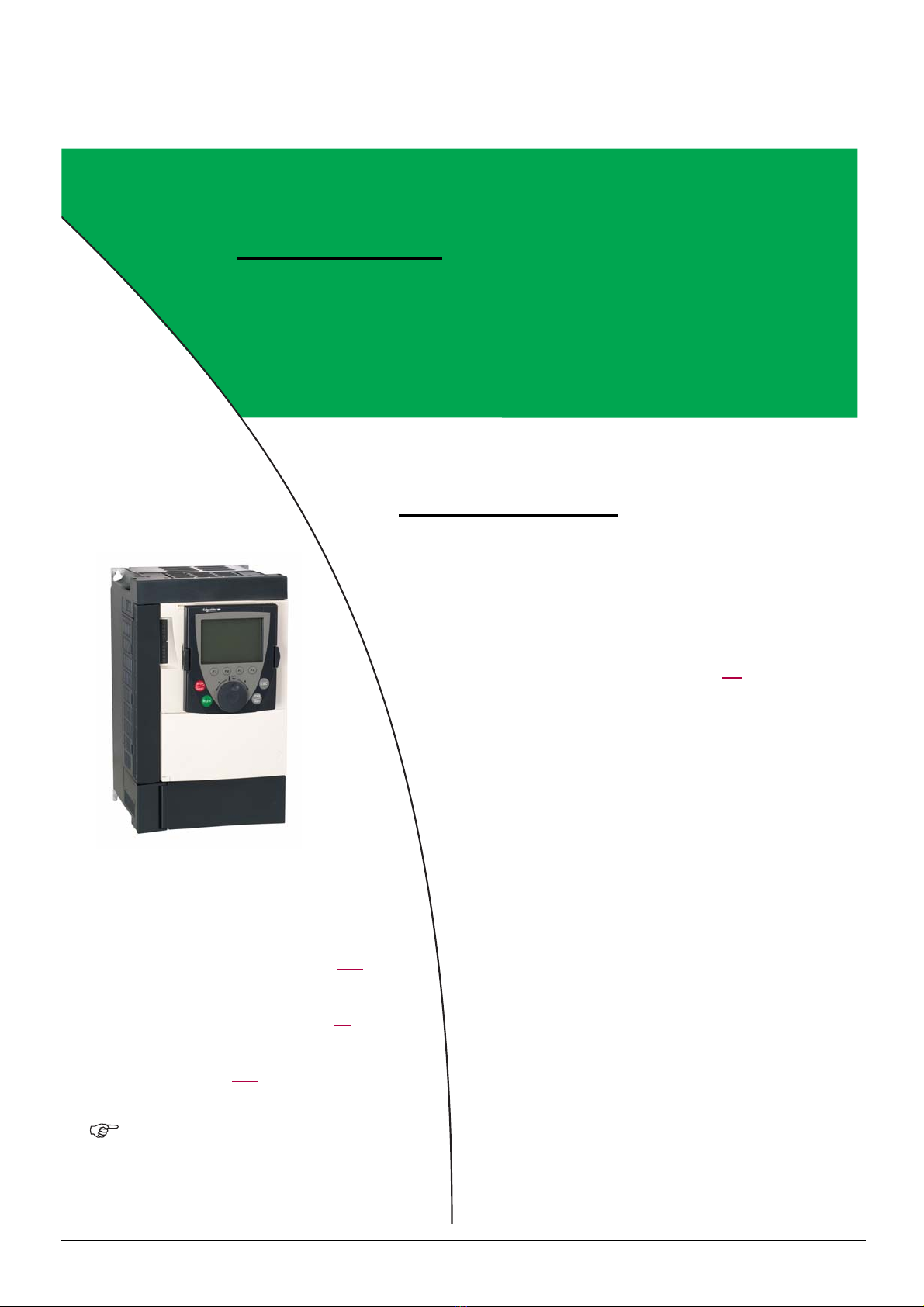
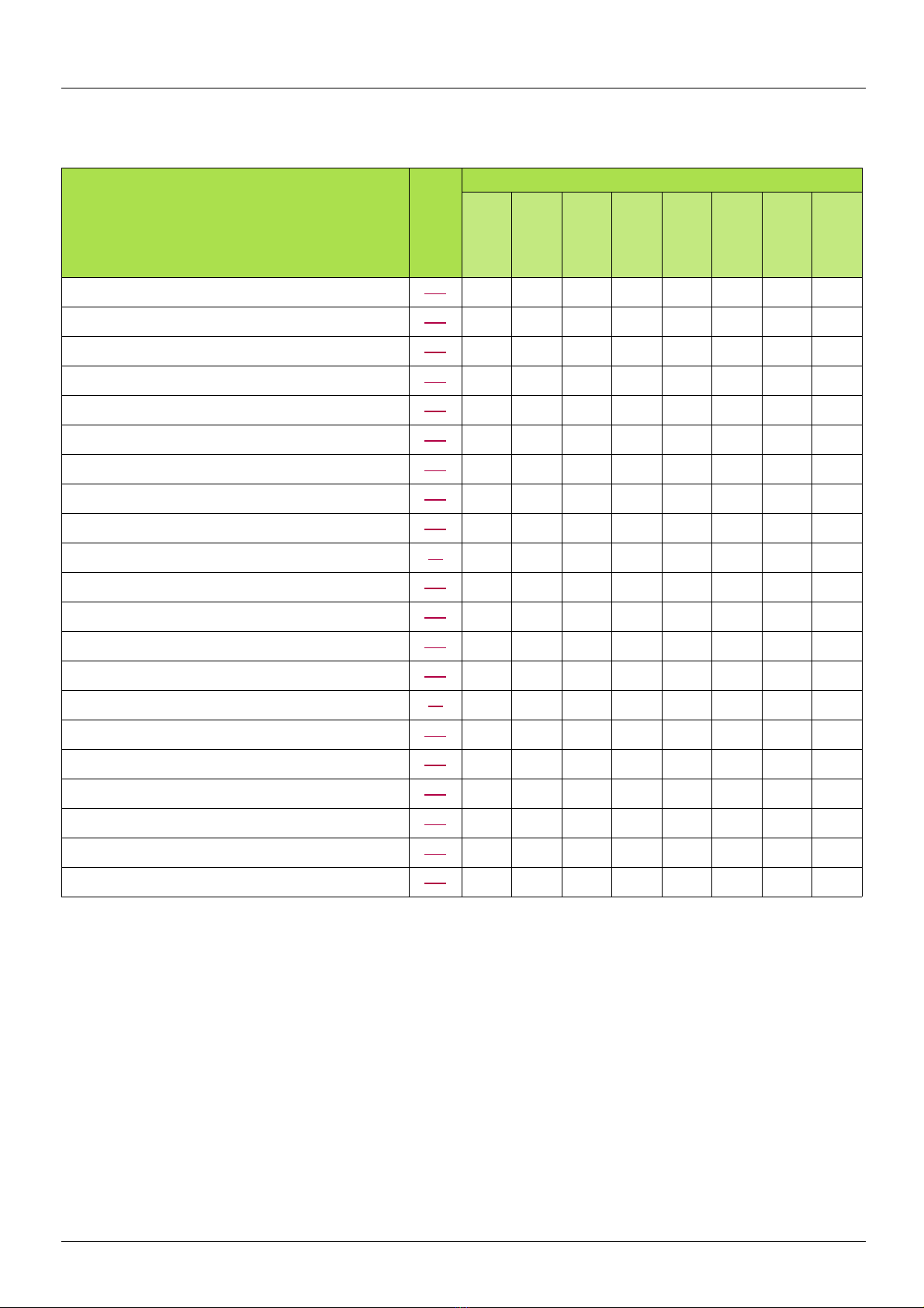
Application functions
The tables on the following pages show the most common combinations of functions and applications, in order to guide your selection.
The applications in these tables relate to the foll owing machines in particular:
• Hoisting: cranes, overhead cranes, gantries (vertical hoisting, translation, slewing), lifting platforms
• Elevators: elevators in retrofit up to 1.2 m/s
• Handling: palletizers/depalletizers, conveyors, roller tables
• Packing: carton packers, labeling machines
• Textiles: weaving looms, carding frames, washing machines, spinners, drawing frames
• Wood: automatic lathes, saws, milling
• High inertia: centrifuges, mixers, unbalanced machines (beam pumps, presses)
• Process
Each machine has its own special features, and the combinations listed here are neither mandatory nor exhaustive.
Some functions are designed specifically for a particular application. In this case, the application is identified by a tab in the
margin on the relevant programming pages.
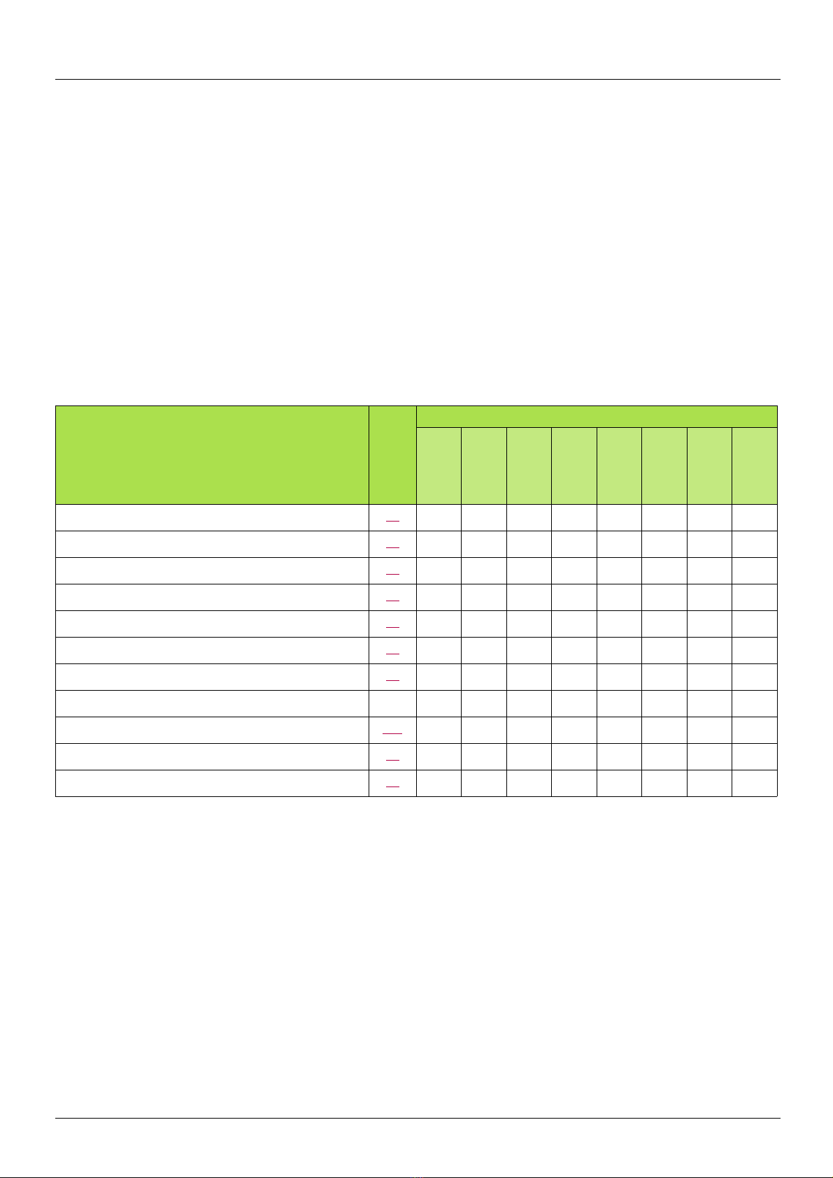
Motor control functions
Applications
Functions Page
V/f ratio
Sensorless flux vector control
Flux vector control with sensor
2-point vector control
Open-loop synchronous motor
Output frequency of up to 1600 Hz
Motor overvoltage limiting
DC bus connection (see User's Manual)
Motor fluxing using a logic input
Switching frequency of up to 16 kHz
Auto-tuning
71
71
71
71
71
69
83
-
154
82
70
Hoisting
Lifts
Handling
Packing
Textiles
Wood
High inertia
b b b
b b b b b b b b
b b b b b b b b
b b
b
b b
b b
b b
b b b
b b b
b b b b b b b b
Process
1755855 12/2009 11
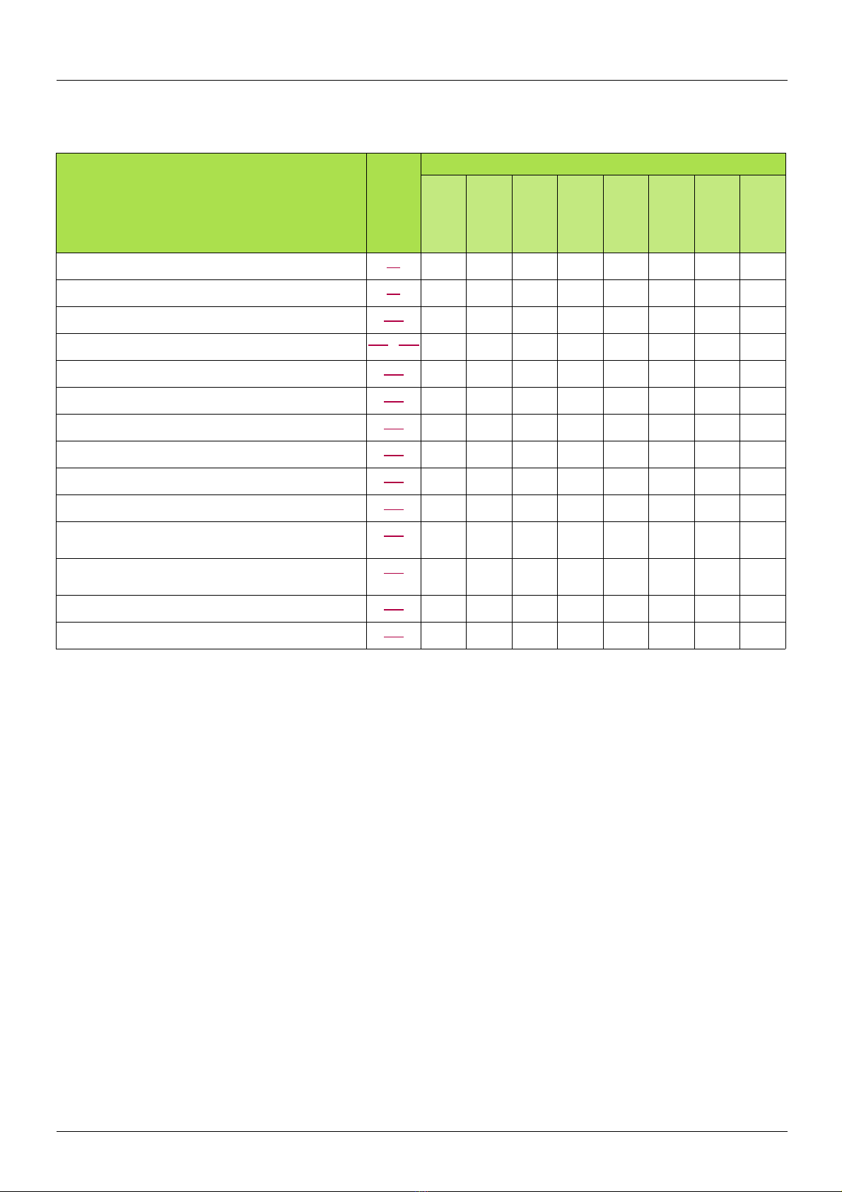
Application functions
Functions on speed references
Functions Page
Applications
Differential bipolar reference 91
Reference delinearization (magnifying glass effect) 93
Frequency control input 125
Reference switching
Reference summing 134
Reference subtraction 134
Reference multiplication 134
S ramps 137
Jog operation 145
Preset speeds 146
+ speed / - speed using single action pushbuttons
(1 step)
+ speed / - speed using double action pushbuttons
(2 steps)
+/- speed around a reference 151
Save reference 153
126 - 135
149
149
Hoisting
Lifts
Handling
Packing
Textiles
Wood
b b b
b b
b b
b
b
b
b
b b b
b b b
b b b b b
b
b b
High inertia
Process
b
b
12 1755855 12/2009
Application functions
Application-specific functions
Functions Page
Applications
Fast stop 141
Limit switch management 155
Brake control 157
Load measurement 166
High-speed hoisting 168
Rope slack 171
PID regulator 173
Torque monitoring 182
Motor/generator torque limit 185
Load sharing 85
Line contactor control 189
Output contactor control 191
Positioning by limit switches or sensors 193
Stop at distance calculated after deceleration limit switch 195
ENA system (mechanical with unbalanced load) 80
Parameter switching 198
Motor or configuration switching 201
Traverse control 205
Stop configuration 141
Evacuation 212
Half floor 213
Hoisting
Lifts
Handling
Packing
Textiles
Wood
High inertia
b b
b b b
b b b
b b
b
b
b b b
b b b b
b b
b b b
b
b b
b b
b
b b b b b b b b
b b b
b
b b b b
b
b
Process
b
1755855 12/2009 13

Application functions
Safety functions/fault management
Functions Page
Applications
Power Removal (safety function, see User's Manual)
Deferred stop on thermal alarm 226
Alarm handling 115
Fault management 218 to 240
IGBT tests 229
Catch a spinning load 222
Braking resistor thermal protection 238
Motor protection with PTC probes 218
Undervoltage management 228
4-20mA loss 230
Uncontrolled output cut (output phase loss) 224
Automatic restart 221
Use of the "Pulse input" input to measure the speed of
rotation of the motor.
Load variation detection 236
-
234
Hoisting
Lifts
Handling
Packing
Textiles
Wood
High inertia
b b b b b b b b
b
b b b b b b b b
b b b b b b b b
b b b b b b b b
b b b
b b b b
b b b b b b b b
b b b
b b b b b b
b
b
b b b
b
Process
14 1755855 12/2009
Setup - Preliminary recommendations
DANGER
UNINTENDED EQUIPMENT OPERATION
• Before turning on and configuring the Altivar 71, check that the PWR (POWER REMOVAL) input is dea ctivat ed (at
state 0) in order to prevent unintended operation.
• Before turning on the drive, or when exiting the configuration menus, check that the inputs assigned to the run
command are deactivated (at state 0) since they can cause the motor to start immediately.
Failure to follow these instructions will result in death or serious injury.
CAUTION
INCOMPATIBLE LINE VOLTAGE
Before turning on and configuring the drive, ensure that the li ne voltage is compatible with the sup ply voltage range shown
on the drive nameplate. The drive may be damaged if the line voltage is not compatible.
Failure to follow this instruction can result in equipment damage.
CAUTION
RISK OF EQUIPMENT DAMAGE
• Avoid operating the contactor frequently (premature ageing of the f ilter capacitors).
• Cycle times < 60 s may result in damage to the pre-charge resistor.
Failure to follow these instructions can result in equipment damage.
DANGER
UNINTENDED EQUIPMENT OPERATION
• Check that changes made to the settings during operation do not present any danger.
• We recommend stopping the drive before making any changes.
Failure to follow these instructions will result in death or serious injury.
Turning on and configuring the drive
Separate control section power supply
Only supply power to the power section the next time the drive is powered up when:
A) The drive control section is powered independently of the power section (P24 and 0V te rminals).
B) Whenever an option card is added or replaced.
Power switching via line contactor
User adjustment and extension of functions
• The display unit and buttons can be used to modify the settings and to extend the functions described in the following pages.
• Return to factory settings is made easy by the [1.12 FACTORY SETTINGS] (FCS-) menu, see page 248.
• There are three types of parameter:
- Display: Values displayed by the drive
- Adjustment: Can be changed during operation or when stopped
- Configuration: Can only be modified when stopped and no braking is taking place. Can be displayed during operation.
1755855 12/2009 15
Setup - Preliminary recommendations
CAUTION
UNINTENDED EQUIPMENT OPERATION
Motor thermal protection will not be provide d by the drive if th e motor current i s less t han 0.2 ti mes the rated drive current.
Provide an alternative means of thermal protection.
Failure to follow this instruction can result in equipment damage.
CAUTION
UNINTENDED EQUIPMENT OPERATION
Motor thermal protection is no longer provided by the drive. Provide an alternative means of thermal protection on every
motor.
Failure to follow this instruction can result in equipment damage.
Starting
Important:
• In factory settings mode, the motor can only be supplied wit h power once the “forward”, “reverse” an d “DC injection st op” commands
have been reset:
- On power-up or a manual fault reset or after a stop command
If they have not been reset, the drive will display "nSt" but will not start.
• If the automatic restart function has been configured ([Automatic restart] (Atr) parameter in the [1.8-FAULT MANAGEMENT] (FLt-)
menu, see page
Test on a low power motor or without a motor
• In factory settings mode, [Output Phase Loss] detection (OPL) page 224 is active (OPL = YES). To check the drive in a test or
maintenance environment without having to switch to a moto r with the same rating as the drive (part icularly useful in the case of high
power drives), deactivate [Output Phase Loss] (OPL = no).
• Configure [Motor control type] (Ctt) = [V/F 2pts] (UF2) or [V/F 5pts] (UF5) ([1.4-MOTOR CONTROL] (drC-) menu, see page 71)
221), these commands are taken into account without a reset being necessary.
Using motors in parallel
• Configure [Motor control type] (Ctt) = [V/F 2pts] (UF2) or [V/F 5pts] (UF5) ([1.4-MOTOR CONTROL] (drC-) menu, see page 71)
16 1755855 12/2009

Setup - Preliminary recommendations
CAUTION
UNINTENDED EQUIPMENT OPERATION
• To protect a motor which has a nominal voltage lower than drive supply voltage, it is mandatory to use
[Vector Control 2pt] (UC2) function in order to limit maximal voltage of the motor lower than network voltage.
• Nevertheless, it is necessary to check that instantaneous voltage applied to the motor (link to DC bus voltage) are
compatible with characteristics of this one.
Failure to follow these instructions can result in equipment damage.
ATV71pppY - Network which presents often under voltage
To assure an optimal running of an ATV71pppY used on network which pre sent s ofte n und er volt ag e (netwo rk vol tage cont ai ned betwe en
425 V and 446 V), it is necessary to adjust [Prevention level] (UPL) = 383 V ([1.8-FAULT MANAGEMENT] (FLt-) menu, see page
Using motor with nominal voltage lower than drive supply voltage
• Configure [Vector Control 2pt] (UC2) = [Yes] (YES) ([1.4-MOTOR CONTROL] (drC-) menu, see page 73)
229).
1755855 12/2009 17
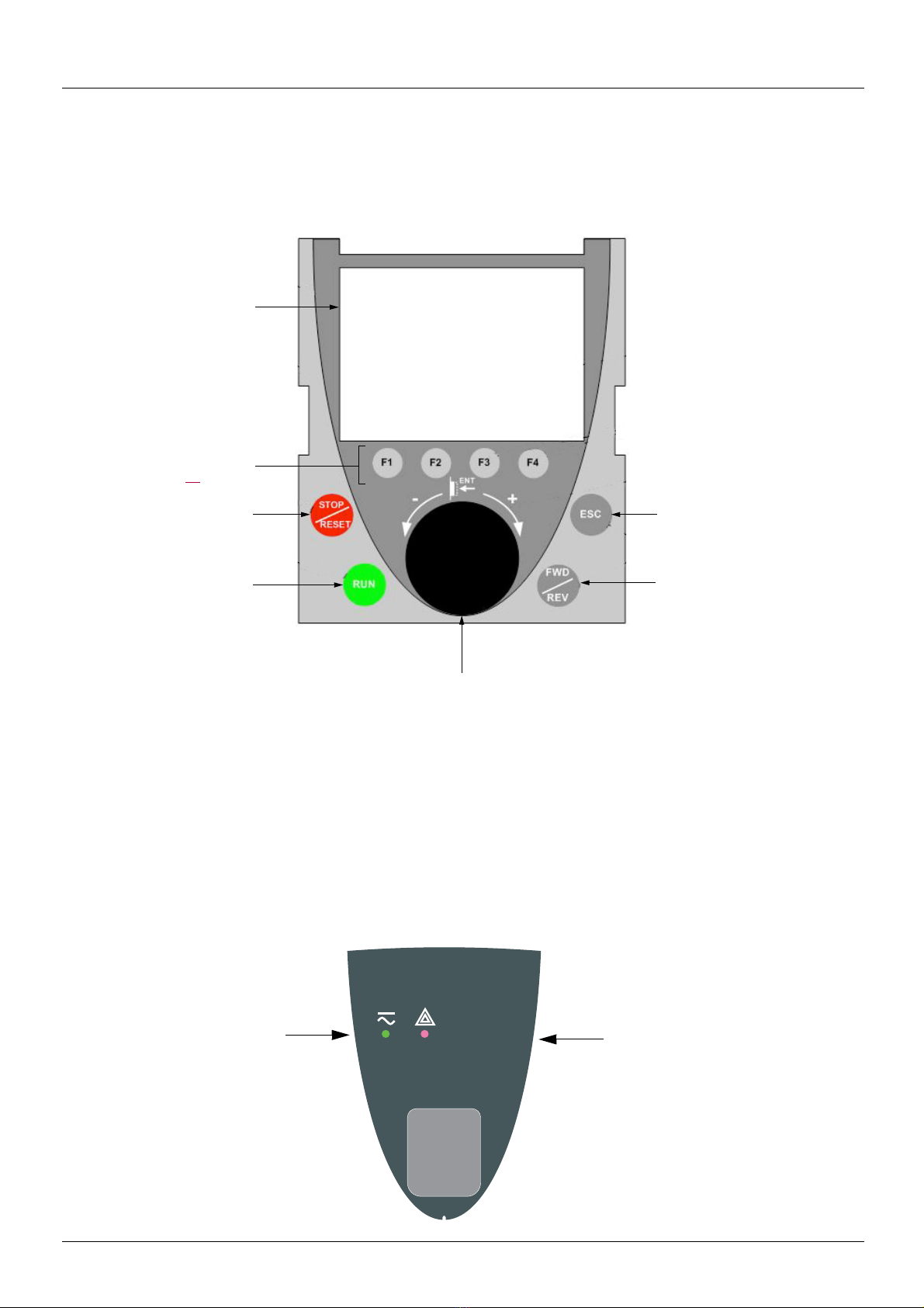
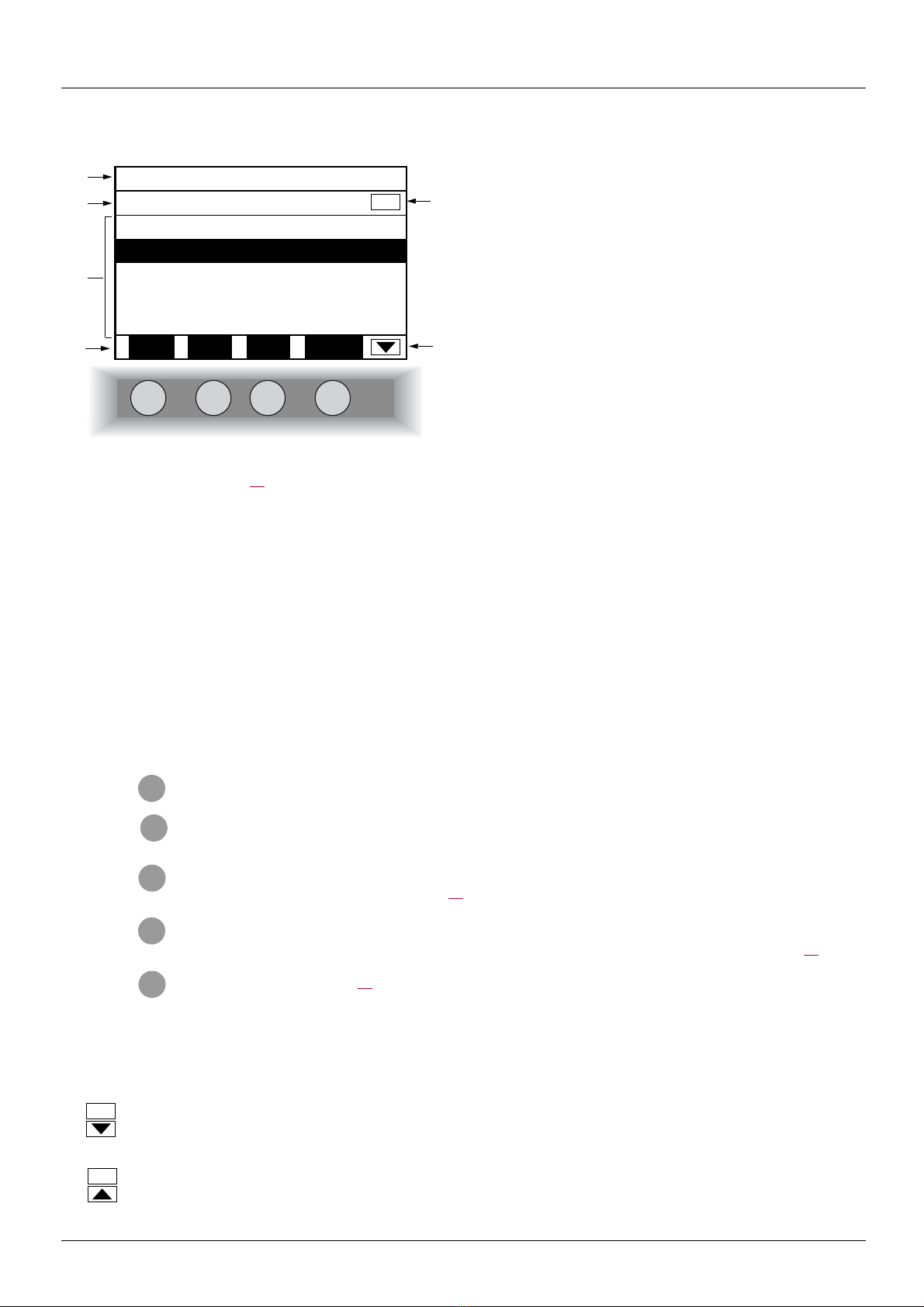
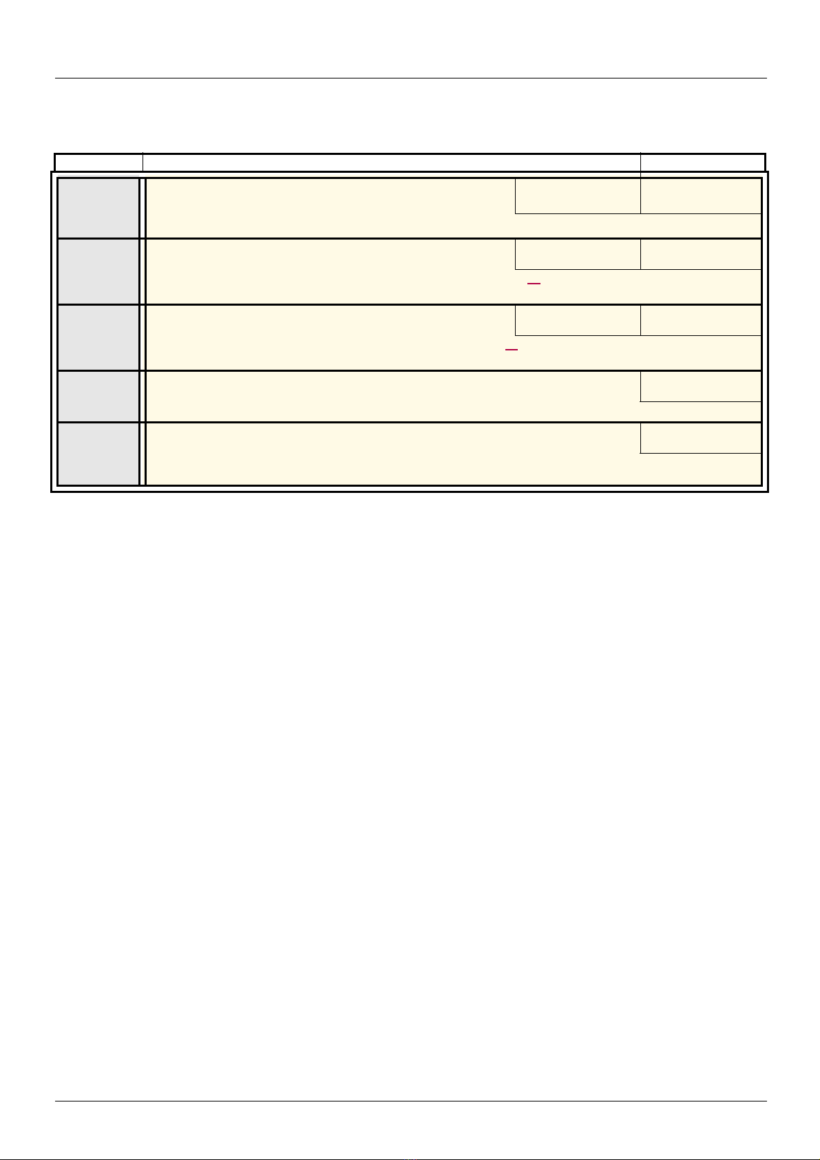
Graphic display terminal
1 Graphic display
2 Function keys
F1, F2, F3, F4,
see page 19
.
3 STOP/RESET
button
4 RUN button
5 Navigation button:
• Press (ENT): - To save the current value
- To enter the selected menu or parameter
• Turn CW/
CCW:
- To increment or decrement a value
- To go to the next or previous line
- To increase or decrease the reference if control via
the terminal is activated
7 ESC key: Aborts a value, a
parameter or a menu to return
to the previous selection
6 Button for reversing the directi on
of rotation of the motor
HMI Modbus
Green LED:
DC bus ON
Red LED:
Fault
Although the graphic display terminal is optional for low-power drives, it is a standard component on high-power drives (see catalog). The
graphic display terminal can be disconnected and connected remotely (on the door of an enclosure for example) using the cables and
accessories available as options (see catalog).
Description of terminal
Note: Buttons 3, 4, 5 and 6 can be used to control the drive directly, if control via the terminal i s ac tivated.
Disconnected terminal
When the terminal is disconnected, 2 LEDs become visible:
18 1755855 12/2009
Graphic display terminal
F1 F2 F3 F4
RDY Term +0.00 Hz 0A
1 DRIVE MENU
1.1 SIMPLY START
1.2 MONITORING
1.3 SETTINGS
1.4 MOTOR CONTROL
1.5 INPUTS / OUTPUTS CFG
Code << >> Quick
1
2
3
4
6
5
• Code F1
•HELP F1
• << F2
• >> F3
• Quick F4
Description of the graphic screen
1. Display line. Its content can be configured; the factory settings show:
• The drive state (see page 20)
• The active control channel:
- Term: Terminals
- HMI: Graphic display terminal
- MDB: Integrated Modbus
- CAN: Integrated CANopen
- NET: Communication card
- APP: Controller Inside card
• Frequency reference
• Current in the motor
2. Menu line. Indicates the name of the current menu or submenu.
3. Menus, submenus, parameters, values, bar charts, etc., are displayed in drop-down window format on a maximum of 5 lines.
The line or value selected by the navigation button is displayed in reverse video.
4. Section displaying the functions assigned to the F1 to F4 keys and aligned with them, for example :
The function keys are dynamic and contextual.
Other functions (application functions) can be assigned to these keys via the [1.6 COMMAND] menu.
If a preset speed is assigned to a function key and if the f uncti on key is p ressed, the mot or will run a t this preset spe ed until anoth er preset
speed or JOG is pressed, speed reference is changed, or Stop key is pressed.
5. Indicates that there are no more levels below this display window.
Indicates that there are more levels below this display window.
6. Indicates that this display window does not scroll further up.
Indicates that there are more levels above this display window.
: Displays the code of the selected parameter, i.e., the code corresponding to the 7-segment display.
: Contextual help
: Navigate horizontally to the left, or go to previous menu/submenu or, for a value, go to the next di gi t up, di spl ayed
in reverse video (see the example on page
: Navigate horizontally to the right or go to next menu/submenu (going to the [2 ACCESS LEVEL] menu in this
example) or, for a value, go to the next digit down, displayed in reverse video (see the example on page
: Quick navigation, see page 25.
21).
21).
1755855 12/2009 19

Graphic display terminal
Drive state codes:
- ACC: Acceleration
- CLI: Current limit
- CTL: Controlled stop on input phase loss
- DCB: DC injection braking in progress
-DEC: Deceleration
- FLU: Motor fluxing in progress
-FST: Fast stop
- NLP: No line power (no line supply on L1, L2, L3)
- NST: Freewheel stop
- OBR: Auto-adapted deceleration
- PRA: Power Removal function active (drive locked)
- RDY: Drive ready
- RUN: Drive running
- SOC: Controlled output cut in progress
- TUN: Auto-tuning in progress
- USA: Undervoltage alarm
20 1755855 12/2009
Graphic display terminal
RDY Term +0.00Hz 0A
5 LANGUAGE
English
Français
Deutsch
Español
Italiano
<< >> Quick
Chinese
Turkish
Russian
PARAMETER SELECTION
1.3 SETTINGS
Ramp increment
Acceleration
Deceleration
Acceleration 2
Deceleration 2
Edit
RDY Term +0.00Hz 0A
Acceleration
9.51 s
Min = 0.01 Max = 99.99
<< >> Quick
>>
RDY Term +0.00Hz 0A
Acceleration
951 s
Min = 0.01 Max = 99.99
<< >> Quick
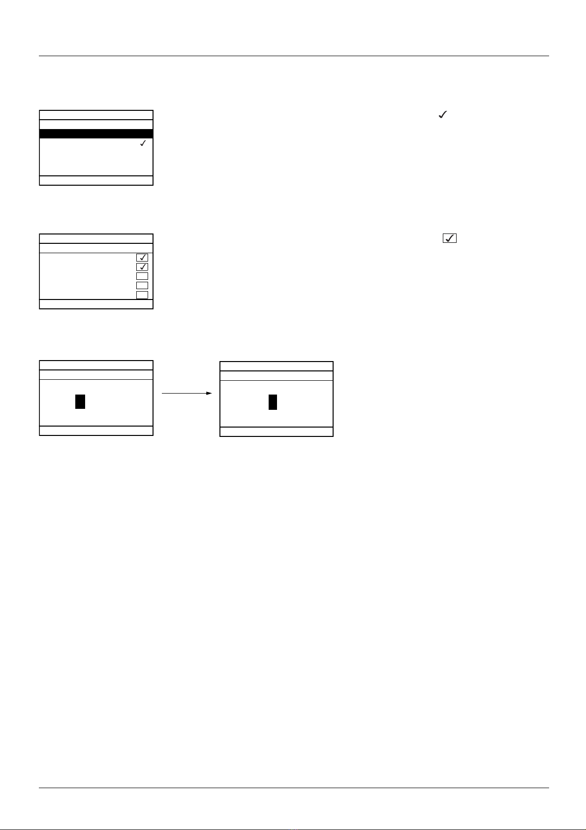
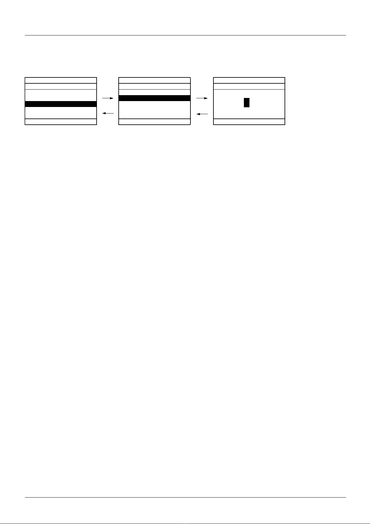
Example configuration windows:
When only one selection is possible, the selection made is indicated by
Example: Only one language can be chosen.
When multiple selection is possible, the selections made are indicated by
Example: A number of parameters can be chosen to form the [USER MENU].
Example configuration window for one value:
The << and >> arrows (keys F2 and F3) are used to select the digit to be modified, and the navigation button is rotated to increase or
decrease this number.
1755855 12/2009 21
Graphic display terminal
ATV31HU22N4
2.2kW/3HP 380/480V
Config. n°1
5 LANGUAGE
English
Français
Deutsch
Español
Italiano
Chinese
Russian
Turkish
RDY Term +0.00Hz 0.0A
2 ACCESS LEVEL
Basic
Standard
Advanced
Expert
RDY Term +0.00Hz 0.0A
1 DRIVE MENU
1.1 SIMPLY START
1.2. MONITORING
1.3. SETTINGS
1.4. MOTOR CONTROL
1.5. INPUTS / OUTPUTS CFG
Code << >> Quick
RDY Term +0.00Hz 0.0A
MAIN MENU
1 DRIVE MENU
2 ACCESS LEVEL
3 OPEN / SAVE AS
4 PASSWORD
5 LANGUAGE
Code Quick
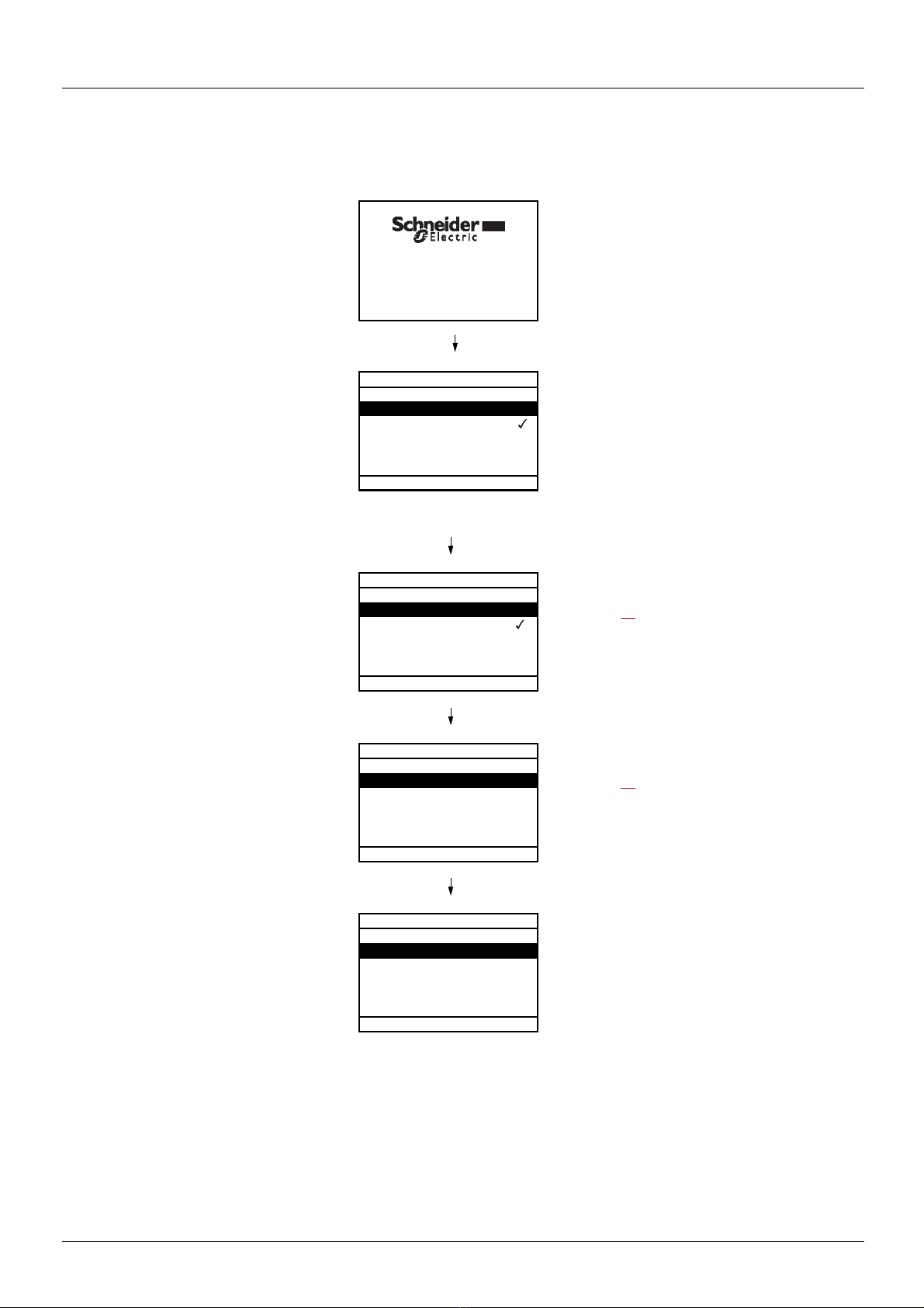
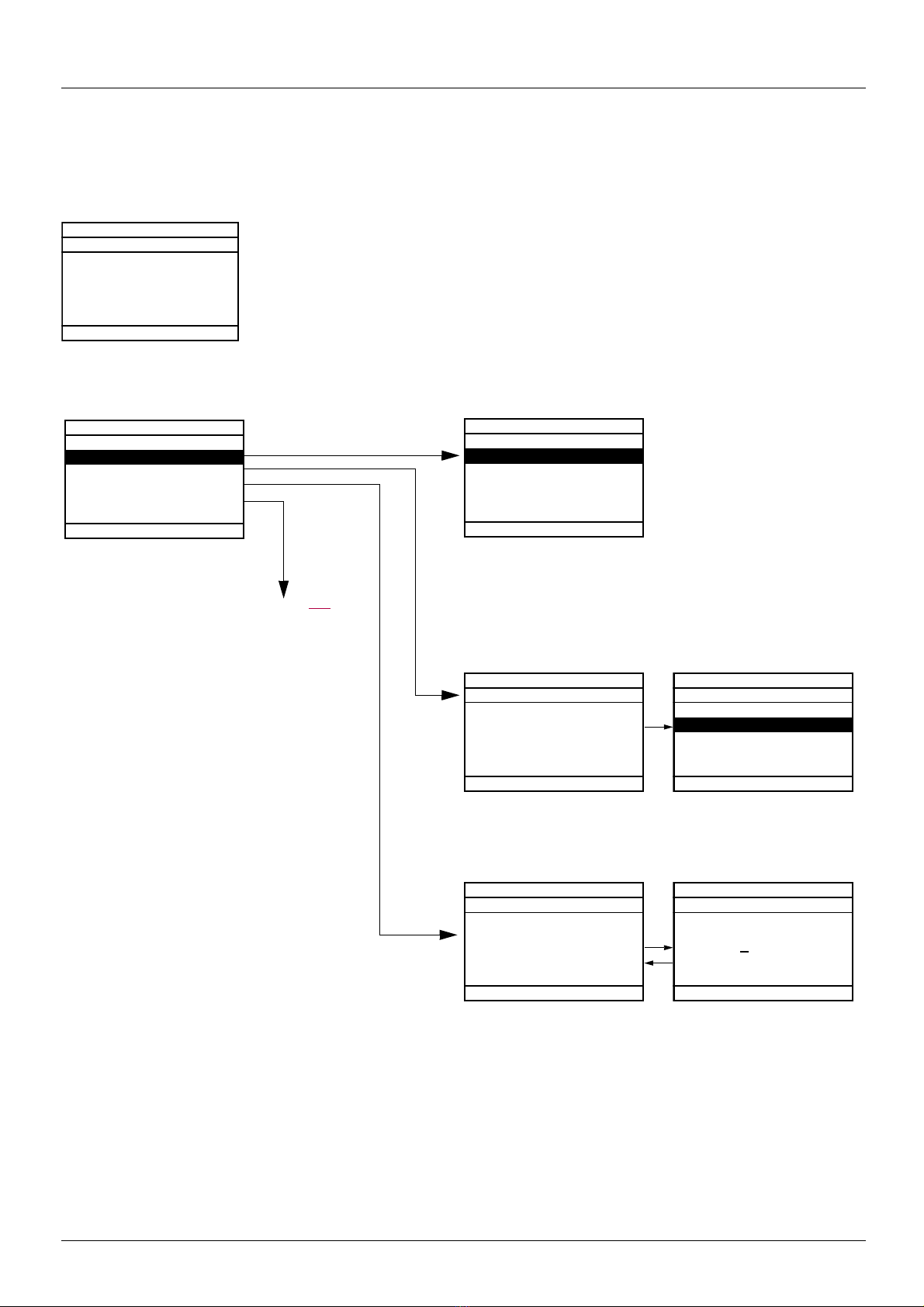
First power-up - [5. LANGUAGE] menu
The first time the drive is powered up, the user will automatically be guided through the menus as far as [1. DRIVE MENU].
The parameters in the [1.1 SIMPLY START] submenu must be configured and auto-tuning performed before the motor is started up.
Display for 3 seconds following power-up
3 seconds
Automatically switches to [5 LANGUAGE]
menu 3 seconds later.
Select the language and press ENT.
ESC
Switches to [2 ACCESS LEVEL] menu
(see page
31)
Select the access level and press ENT.
Switches to [1 DRIVE MENU]
(see page
27)
Press ESC to return to [MAIN MENU]
22 1755855 12/2009
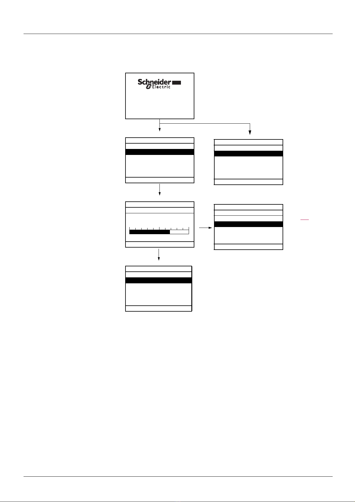
Graphic display terminal
3 seconds later, switches to
[1. DRIVE MENU] or to
[1.14 PROGRAMMABLE CARD].
If no operator inputs are made,
switches to "Display" automatically
10 seconds later (the display will
vary depending on the selected
configuration).
Users can return to [MAIN MENU]
by pressing ENT or ESC.
3 seconds
10 seconds
ESC
ATV71HU22N4
2.2kW/3HP 380/480V
Config. n°1
RDY Term +38Hz 0A
1. DRIVE MENU
1.1 SIMPLY START
1.2 MONITORING
1.3 SETTINGS
1.4 MOTOR CONTROL
1.5 INPUTS / OUTPUTS CFG
Code << >> Quick
RDY Term +38Hz 0A
Frequency ref.
Min=0 Max=60
Quick
RDY Term +38Hz 0A
MAIN MENU
1 DRIVE MENU
2 ACCESS LEVEL
3 OPEN / SAVE AS
4 PASSWORD
5 LANGUAGE
Code Quick
38 Hz
RDY Term +0.00Hz 0A
1.14 PROGRAMMABLE CARD
Modbus add Prg C. :17
DATE/TIME SETTINGS
<< >> Quick
RDY Term +0.00Hz 0A
1.3 SETTINGS
Ramp increment: 01
Acceleration 9.51 s
Deceleration: 9.67 s
Acceleration 2: 12.58 s
Deceleration 2: 13.45 s
Code << >> Quick
Menu selected in
[Power up menu]
page 265
ENT
or, if the Controller Inside card is present
Subsequent power ups
1755855 12/2009 23
Graphic display terminal
RDY Term +0.00Hz 0A
1 DRIVE MENU
1.1 SIMPLY START
1.2 MONITORING
1.3 SETTINGS
1.4 MOTOR CONTROL
1.5 INPUTS / OUTPUTS CFG
Code << >> Quick
ENT
ESC
RDY Term +0.00Hz 0A
1.3 SETTINGS
Ramp increment: 01
Acceleration 9.51 s
Deceleration: 9.67 s
Acceleration 2: 12.58 s
Deceleration 2: 13.45 s
Code << >> Quick
ENT
ENT or
ESC
RDY Term +0.00Hz 0A
Acceleration
9.51 s
Min = 0.01 Max = 99.99
<< >> Quick
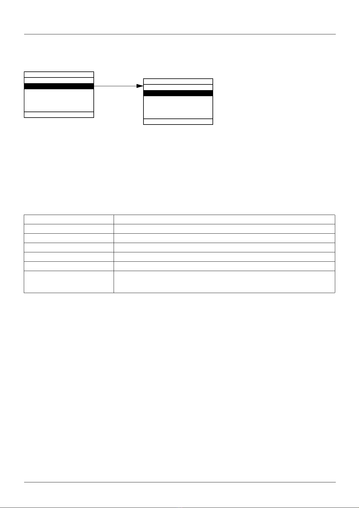
Programming: Example of accessing a parameter
Accessing the acceleration ramp
Note:
• To select a parameter:
- Turn the navigation button to scroll vertically.
• To modify a parameter:
- Use the << and >> keys (F2 and F3) to scroll horizontally and select the digit to be modified (the selected di git chan ges to white
on a black background).
- Turn the navigation button to modify the digit.
• To cancel the modification:
-Press ESC.
• To save the modification:
- Press the navigation button (ENT).
24 1755855 12/2009
Graphic display terminal
RDY Term +0.00Hz 0A
1.4 MOTOR CONTROL
Standard mot. freq: 5 0Hz IEC
Rated motor power: 0.37 kW (0.5 HP)
Rated motor volt.: 206 V
Rated mot. current: 1.0 A
Rated motor freq.: 50.0 Hz
Code << >> Quick
ENT
RDY Term +0.00Hz 0A
QUICK NAVIGATION
RETURN TO MAIN MENU
DIRECT ACCESS TO...
10 LAST MODIFICATIONS
GOTO MULTIPOINT SCREEN
Code
See page 266
RDY Term +0.00Hz 0A
MAIN MENU
1 DRIVE MENU
2 ACCESS LEVEL
3 OPEN / SAVE AS
4 PASSWORD
5 LANGUAGE
Code Quick
RDY Term +0.00Hz 0A
DIRECT ACCESS TO...
1.3
SETTINGS
<< >>
ENT
RDY Term +0.00Hz 0A
1.3 SETTINGS
Ramp increment: 01
Acceleration 9.51 s
Deceleration: 9.67 s
Acceleration 2: 12.58 s
Deceleration 2: 13.45 s
Code << >> Quick
RDY Term +0.00Hz 0A
10 LAST MODIFICATIONS
Acceleration: 10 s
ENA prop.gain: 1.2
Rated mot. current: 15 A
Preset speed 4: 20 Hz
Preset speed 5: 30 Hz
Code
ESC
ENT
RDY Term +0.00Hz 0A
Rated mot. current
15.0 A
<< >>
Quick navigation
If the "Quick" function is displayed above the F4 key, you can gain quick access to a parameter from any screen.
Example:
Press F4 to access the Quick screen, which contains
4 selection options.
• [HOME]: Return to [MAIN MENU].
• [DIRECT ACCESS TO...] : Opens the direct access window, which
will contain the text "1". The function keys << and >> (F2 and F3)
can be used to select each of the numbers and the navigation
button to increment or decrement the numbers: 1.3 in the example
below.
• [10 LAST MODIFICATIONS]: Opens a window in which the l ast 10
parameters modified can be accessed directly.
1755855 12/2009 25
Graphic display terminal
RDY Term +0.00Hz 0A
MAIN MENU
1 DRIVE MENU
2 ACCESS LEVEL
3 OPEN / SAVE AS
4 PASSWORD
5 LANGUAGE
Code Quick
6 MONITORING CONFIG.
7 DISPLAY CONFIG.
RDY Term +0.00Hz 0A
1 DRIVE MENU
1.1 SIMPLY START
1.2 MONITORING
1.3 SETTINGS
1.4 MOTOR CONTROL
1.5 INPUTS / OUTPUTS CFG
Code << >> Quick
1.6 COMMAND
1.7 APPLICATION FUNCT.
1.8 FAULT MANAGEMENT
1.9 COMMUNICATION
1.10 DIAGNOSTICS
1.11 IDENTIFICATION
1.12 FACTORY SETTINGS
1.13 USER MENU
1.14 PROGRAMMABLE CARD
[MAIN MENU] - Menu mapping
Content of [MAIN MENU] menus
[1 DRIVE MENU] See next page
[2 ACCESS LEVEL] Defines which menus can be accessed (level of complexity)
[3 OPEN / SAVE AS] Can be used to save and recover drive configuration files
[4 PASSWORD] Provides password protection for the configuration
[5 LANGUAGE] Language selection
[6 MONITORING CONFIG.] Customization of information displayed on the graphic display terminal during operation
[7 DISPLAY CONFIG.] • Customization of parameters
• Creation of a customized user menu
• Customization of the visibility and protection mechanisms for menus and parameters
26 1755855 12/2009

Graphic display terminal
[1 DRIVE MENU]
RDY Term +0.00Hz 0A
1.1 SIMPLY START
1.2 MONITORING
1.3 SETTINGS
1.4 MOTOR CONTROL
1.5 INPUTS / OUTPUTS CFG
1.6 COMMAND
1.7 APPLICATION FUNCT.
1.8 FAULT MANAGEMENT
1.9 COMMUNICATION
1.10 DIAGNOSTICS
1.11 IDENTIFICATION
1.12 FACTORY SETTINGS
1.13 USER MENU
1.14 PROGRAMMABLE CARD
1 DRIVE MENU
Code << >> Quick
Content of [1. DRIVE MENU] menus:
[1.1 SIMPLY START]: Simplified menu for a quick start
[1.2 MONITORING]: Visualization of current, motor and input/output values
[1.3 SETTINGS]: Accesses the adjustment parameters, which can be modified during operation
[1.4 MOTOR CONTROL]: Motor parameters (motor nameplate, auto-tuning, switching frequency, control algorithms, etc.)
[1.5 INPUTS / OUTPUTS CFG]: I/O configuration (scaling, filtering, 2-wire control, 3-wire control, etc.)
[1.6 COMMAND]: Configuration of command and reference channels (graphic d ispl ay t erminal , t ermin als, bu s, e tc.)
[1.7 APPLICATION FUNCT.] : Configuration of application functions (e.g., preset speeds, PID, brake logic control, etc.)
[1.8 FAULT MANAGEMENT]: Configuration of fault management
[1.9 COMMUNICATION]: Communication parameters (fieldbus)
[1.10 DIAGNOSTICS]: Motor/drive diagnostics
[1.11 IDENTIFICATION]: Identifies the drive and the internal options
[1.12 FACTORY SETTINGS]: Access to configuration files and return to factory settings
[1.13 USER MENU]: Specific menu set up by the user in the [7. DISPLAY CONFIG.] menu
[1.14 PROGRAMMABLE CARD]: : Configuration of optional Controller Inside card
1755855 12/2009 27
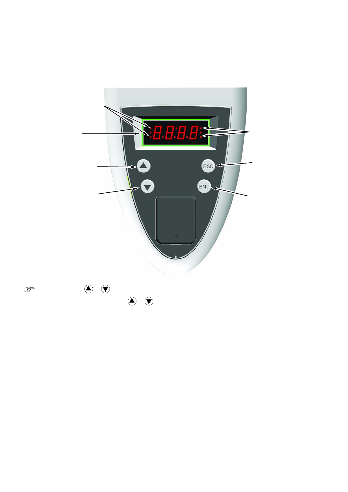
Integrated display terminal
• Four 7-segment
displays
• Enters a menu or
parameter, or saves the
displayed parameter or
value
• Returns to the previous
menu or parameter, or
increases the
displayed value
• Exits a menu or parameter,
or aborts the displayed
value to return to the
previous value in the
memory
• Goes to the next menu
or parameter, or
decreases the
displayed value
• 2 CANopen status LEDs
• 2 Modbus status LEDs
Note:
Low-power Altivar 71 drives (see catalog) feature an integrated display terminal with a 7-segment 4-digit display. The graphic display
terminal described on the previous pages can also be connected to these drives as an option.
Functions of the display and the keys
• Pressing or does not store the selection.
• Press and hold down (>2 s) or to scroll through the data quickly.
Save and store the selection: ENT
The display flashes when a value is stored.
Normal display, with no fault present and no startup:
- 43.0 : Display of the parameter selected in the SUP menu (default selection: motor frequency)
- CLI: Current limit
- CtL: Controlled st op on in pu t phase loss
- dCb: DC injection braking in progress
- FLU: Motor fluxing in progress
- FSt: Fast stop.
- nLP: No line power (no line supply on L1, L2, L3)
- nSt: Freewheel stop
- Obr: Auto-adapted deceleration
- PrA: Power Removal function active (drive locked)
- rdY = Drive ready
- SOC: Controlled output cut in progress
- tUn: Auto-tuning in progress
- USA: Undervoltage alarm
The display flashes to indicate the presence of a fault.
28 1755855 12/2009
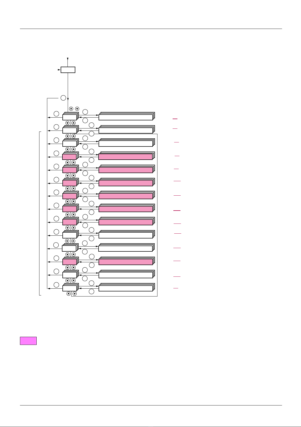
Integrated display terminal
XXX
CtL-
FUn-
SIM-
I-O-
SEt-
SUP-
ESC
ESC
ESC
ESC
ESC
ESC
ESC
ESC
ENT
ENT
ESC
ENT
ESC
ENT
ESC
ENT
ESC
ENT
ESC
ENT
ESC
ENT
ESC
FCS-
LAC-
CON-
FLt-
ESC
ESC
ESC
ESC
ENT
ESC
ENT
ESC
ENT
ESC
ENT
ESC
ENT
ESC
SPL-
ESC
ENT
ESC
drC-
COd-
USr-
ESC
ENT
ESC
Displays the state of the drive
SETTINGS
APPLICATION FUNCT.
INPUTS / OUTPUTS CFG
FAULT MANAGEMENT
SIMPLY START
Menus
MONITORING
MOTOR CONTROL
COMMAND
Power-up
FACTORY SETTINGS
PASSWORD
ACCESS LEVEL
COMMUNICATION
(page 54) Adjustment parameters, can be modified during
operation
(page 129
)Configuration of application functions (e.g., preset
speeds, PID, brake logic control, etc.)
(page 88
) I/O configuration (scaling, filtering, 2-wire control,
3-wire control, etc.)
(page 217
) Configuration of fault management
(page 37
) Simplified menu for fast startup
(page 45
) Visualization of current, motor and i nput/output values
(page 70
) Motor parameters (motor nameplate, auto-tuning,
switching frequency, control algorithms, etc.)
(page 116
) Configuration of command and reference channels
(graphic display terminal, terminals, bus, etc.)
(page 248
) Access to configuration files and return to factory
settings
(page 255
)
(page 31
)
(page 241
) Communication parameters (fieldbus)
(page 251
) Specific menu, set up by the user using the graphic
display terminal.
USER MENU
PROGRAMMABLE CARD
(page 252
) Menu for the Controller Inside card, if present.
Accessing menus
A dash appears after menu and submenu codes to differentiate them from parameter codes.
Examples: FUn- menu, ACC parameter.
1755855 12/2009 29
The grayed-out menus may not be accessible depending on the control access (LAC) configuration.
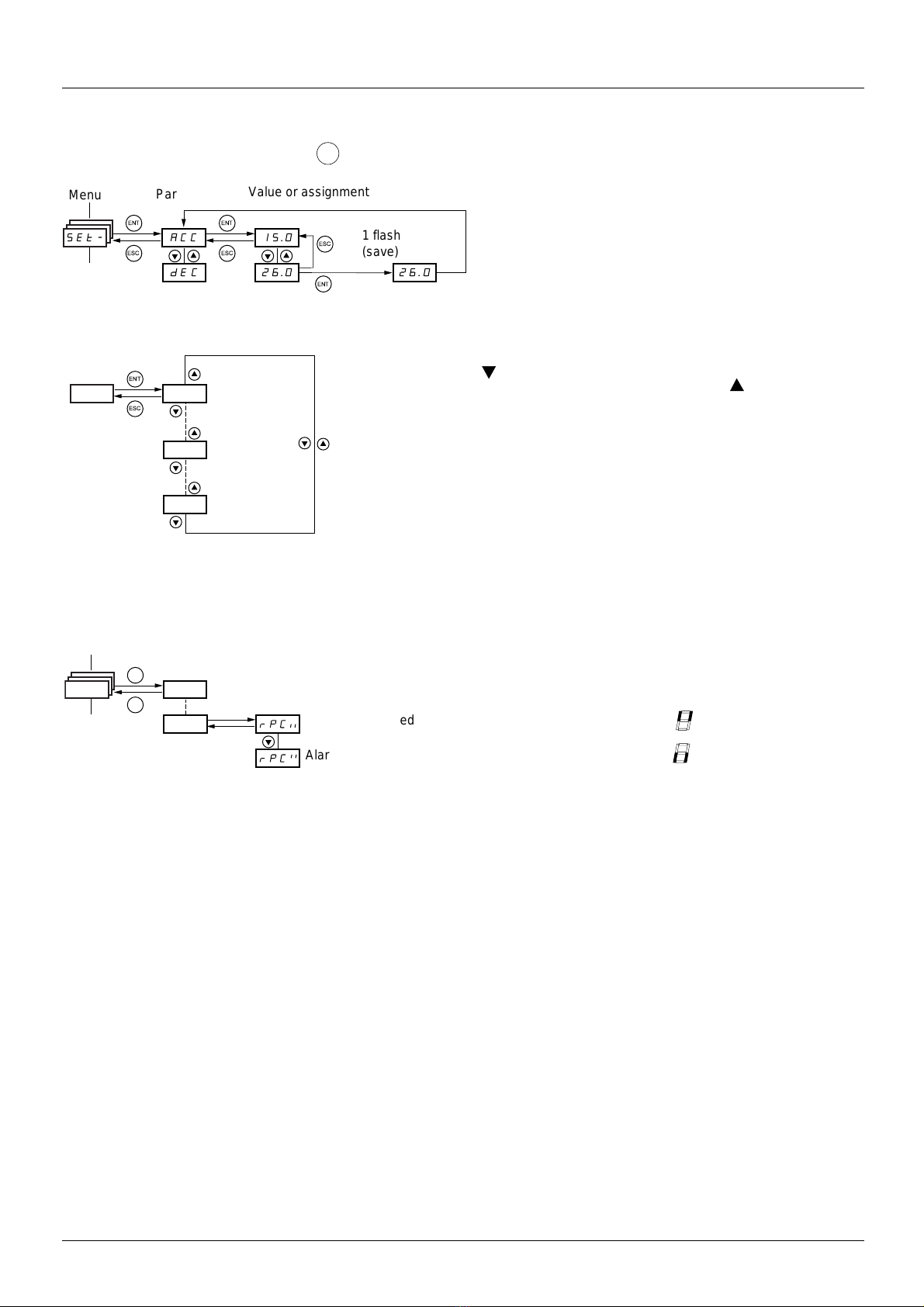
Integrated display terminal
ENT
ACC 15.0
ENT
ESC
ENT
ESC
26.0 26.0
ESC
dEC
ENT
SEt-
Menu
Value or assignment
1 flash
(save)
Parameter
(Next parameter)
ENT
ESC
1
st
n
th
last
Menu
ENT
ESC
I-O-
Alarm not selected
Alarm selected
Accessing menu parameters
Save and store the displayed selection :
The display flashes when a value is stored.
All the menus are "drop-down" type menus, which means that after the last pa rameter, if
you continue to press , you will return to the first parameter an d, conve rsely, you can
switch from the first parameter to the last parameter by pressing .
Selection of multiple assignments for one parameter
Example: List of group 1 alarms in [INPUTS / OUTPUTS CFG]
menu (I-O-)
A number of alarms can be selected by "checking" them as
follows.
The digit on the right indicates: selected
not selected.
The same principle is used for all multiple select ions.
30 1755855 12/2009
[2. ACCESS LEVEL] (LAC-)
RDY Term +0.00Hz 0A
2 ACCESS LEVEL
Basic
Standard
Advanced
Expert
<< >> Quick
RDY Term +0.00Hz 0A
MAIN MENU
1 DRIVE MENU
2 ACCESS LEVEL
3 OPEN / SAVE AS
4 PASSWORD
5 LANGUAGE
Code << >> Quick
RDY Term +0.00Hz 0A
1. DRIVE MENU
1.1 SIMPLY START
1.2. MONITORING
1.3. SETTINGS
1.11. IDENTIFICATION
1.12. FACTORY SETTINGS
Code << >> Quick
1.13 USER MENU
RDY Term +0.00Hz 0A
MAIN MENU
1 DRIVE MENU
2 ACCESS LEVEL
3 OPEN / SAVE AS
4 PASSWORD
5 LANGUAGE
Code Quick
6 MONITORING CONFIG.
RDY Term +0.00Hz 0A
1 DRIVE MENU
1.1 SIMPLY START
1.2 MONITORING
1.3 SETTINGS
1.4 MOTOR CONTROL
1.5 INPUTS / OUTPUTS CFG
Code << >> Quick
1.6 COMMAND
1.7 APPLICATION FUNCT.
1.8 FAULT MANAGEMENT
1.9 COMMUNICATION
1.10 DIAGNOSTICS
1.11 IDENTIFICATION
1.12 FACTORY SETTINGS
1.13 USER MENU
1.14 PROGRAMMABLE CARD
RDY Term +0.00Hz 0A
MAIN MENU
1 DRIVE MENU
2 ACCESS LEVEL
3 OPEN / SAVE AS
4 PASSWORD
5 LANGUAGE
Code Quick
6 MONITORING CONFIG.
7 DISPLAY CONFIG.
RDY Term +0.00Hz 0A
MAIN MENU
1 DRIVE MENU
2 ACCESS LEVEL
3 OPEN / SAVE AS
4 PASSWORD
5 LANGUAGE
Code Quick
6 MONITORING CONFIG.
7 DISPLAY CONFIG.
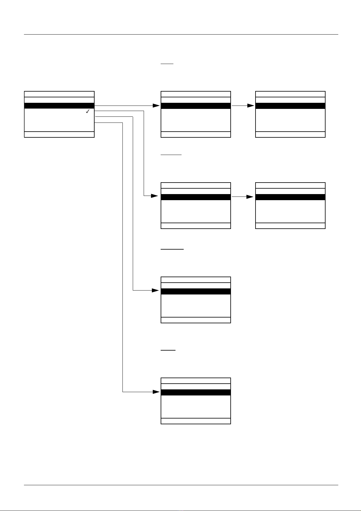
With graphic display terminal
Basic
Access to 5 menus only, and access to 6 submenus only in the
[1. DRIVE MENU] menu.
A single function can be assigned to each input.
Standard
This is the factory-set level. Access to 6 menus only, and access to all
submenus in the [1. DRIVE MENU] menu.
A single function can be assigned to each input.
1755855 12/2009 31
Advanced
Access to all menus and submenus.
Several functions can be assigned to
each input.
Expert
Access to all menus and submenus as for [Advanced] level, and access to
additional parameters.
Several functions can be assigned to each input.
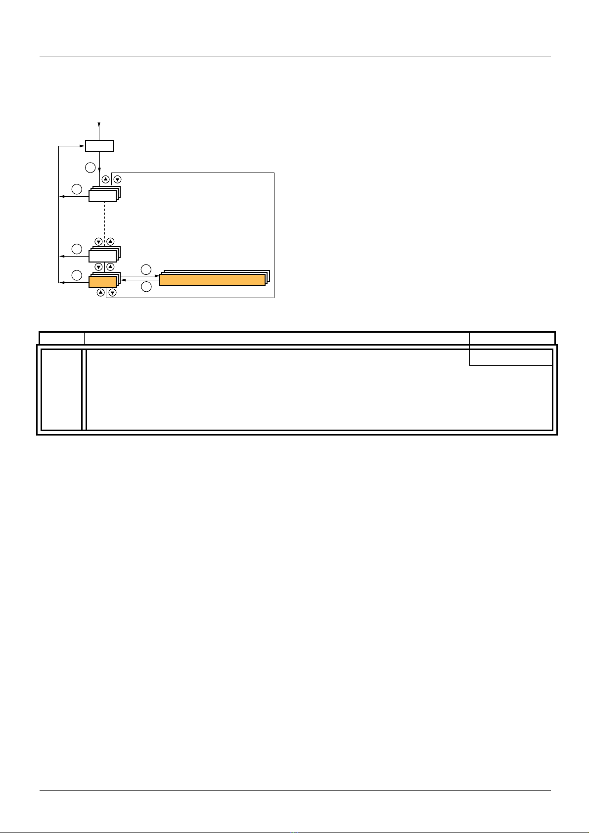
[2. ACCESS LEVEL] (LAC-)
XXX
SIM-
ESC
ESC
ENT
LAC-
ESC
ENT
ESC
COd-
Displays the state of the drive
ACCESS LEVEL
Power-up
With integrated display terminal:
Code Name/Description Factory setting
LAC-
bAS
• bAS: Limited access to SIM, SUP, SEt, FCS, USr, COd and LAC menus. Only one function can be assigned to
Std
each input.
Std
Adu
Epr
• Std: Access to all menus on the integrated display terminal. Only one function can be assigned to each input.
• AdU: Access to all menus on the integrated display terminal. Several functions can be assigned to each input.
• EPr: Access to all menus on the integrated display te rminal and access to additional p arameters. Several functions
can be assigned to each input.
32 1755855 12/2009
[2. ACCESS LEVEL] (LAC-)
Comparison of the menus that can be accessed on the graphic display terminal/
integrated display terminal
Graphic display terminal Integrated display terminal Access level
[2 ACCESS LEVEL] LAC- (Access level)
[3 OPEN/SAVE AS] [4 PASSWORD] COd- (Password)
[5 LANGUAGE] [1 DRIVE MENU] [1.1 SIMPLY START] SIM- (Simply start)
[1.2 MONITORING] SUP-(Monitoring)
[1.3 SETTINGS] SEt- (Settings)
[1.11 IDENTIFICATION] [1.12 FACTORY SETTINGS] FCS- (Factory settings)
[1.13 USER MENU] USr- (User menu)
A single function can be assigned to each input. A single function can be assigned to
each input.
[1.4 MOTOR CONTROL] drC- (Motor control)
[1.5 INPUTS / OUTPUTS CFG] I-O- (I/O configuration)
[1.6 COMMAND] CtL- (Command)
[1.7 APPLICATION FUNCT.] FUn- (Application functions)
[1.8 FAULT MANAGEMENT] FLt- (Fault management)
[1.9 COMMUNICATION] COM- (Communication)
[1.10 DIAGNOSTICS] [1.14 PROGRAMMABLE CARD] (1) PLC- (Controller Inside card) (1)
[6 MONITORING CONFIG.] -
A single function can be assigned to each input. A single function can be assigned to
each input.
[7 DISPLAY CONFIG.] -
Several functions can be assigned to each input. Several functions can be assigned
to each input.
Expert parameters Expert parameters
Several functions can be assigned to each input. Several functions can be assigned
to each input.
Basic bAS
Advanced AdU
Standard Std(factory setting)
Expert EPr
(1)Can be accessed if the Controller Inside card is present.
1755855 12/2009 33

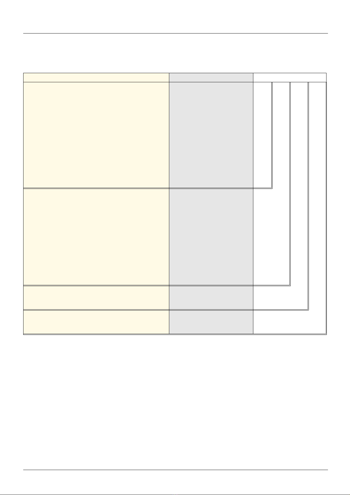
Structure of parameter tables
5
2
3
1
4
6
8
7
1. Name of menu on 4-digit 7-segment display.
2. Submenu code on 4-digit 7-segment display.
3. Parameter code on 4-digit 7-segment display.
4. Parameter value on 4-digit 7-segment display.
5. Name of menu on graphic display terminal.
6. Name of submenu on graphic display terminal.
7. Name of parameter on graphic display terminal.
8. Value of parameter on graphic display terminal.
The parameter tables in the descriptio ns of the various menus can be used wit h both the graphi c display terminal an d the integrated display
terminal. They, therefore, contain information for these two terminals in accordance with the description below.
Example:
[1.7 APPLICATION FUNCT.] (FUn-)
Code Name/Description Adjustment range Factory setting
UPd-
USP
LI1
Note :
• The text in square brackets [ ] indicates what you will see on the graphic display terminal.
• The factory settings correspond to [Macro configuration] (CFG) = [Start/Stop] (StS). This is the macro configuration set at
the factory.
b [+/- SPEED]
Function can be accessed for reference channel [Ref.2 channel] (Fr2) = [+/- speed] (UPdt) ,
see page 126
M [+ speed assignment]
no
v [No] (nO): function inactive
v [LI1] (LI1)
[No] (nO)
34 1755855 12/2009

Interdependence of parameter values
The configuration of certain parameters modifies the a dju stment ra nge of ot her p aramet ers, in order to redu ce t he risk of error s. This may
result in the modification of a factory setting or a value you have already selected.
Example:
1. [Current Limitation] (CLI) page 61 set to 1.6 In or left at its factory setting, 1.5 In
2. [Switching freq.] (SFr) page 61 set to 1 kHz (and confirmed with "ENT") restrict s [Current Limitation] (CLI) to 1.36 In
3. If [Switching freq.] (SFr) is increased to 4 kHz, [Current limitation] (CLI) is no longer restricted, but remains at 1.36 In. If you require
1.6
In, you must reset [Current Limitation] (CLI).
1755855 12/2009 35
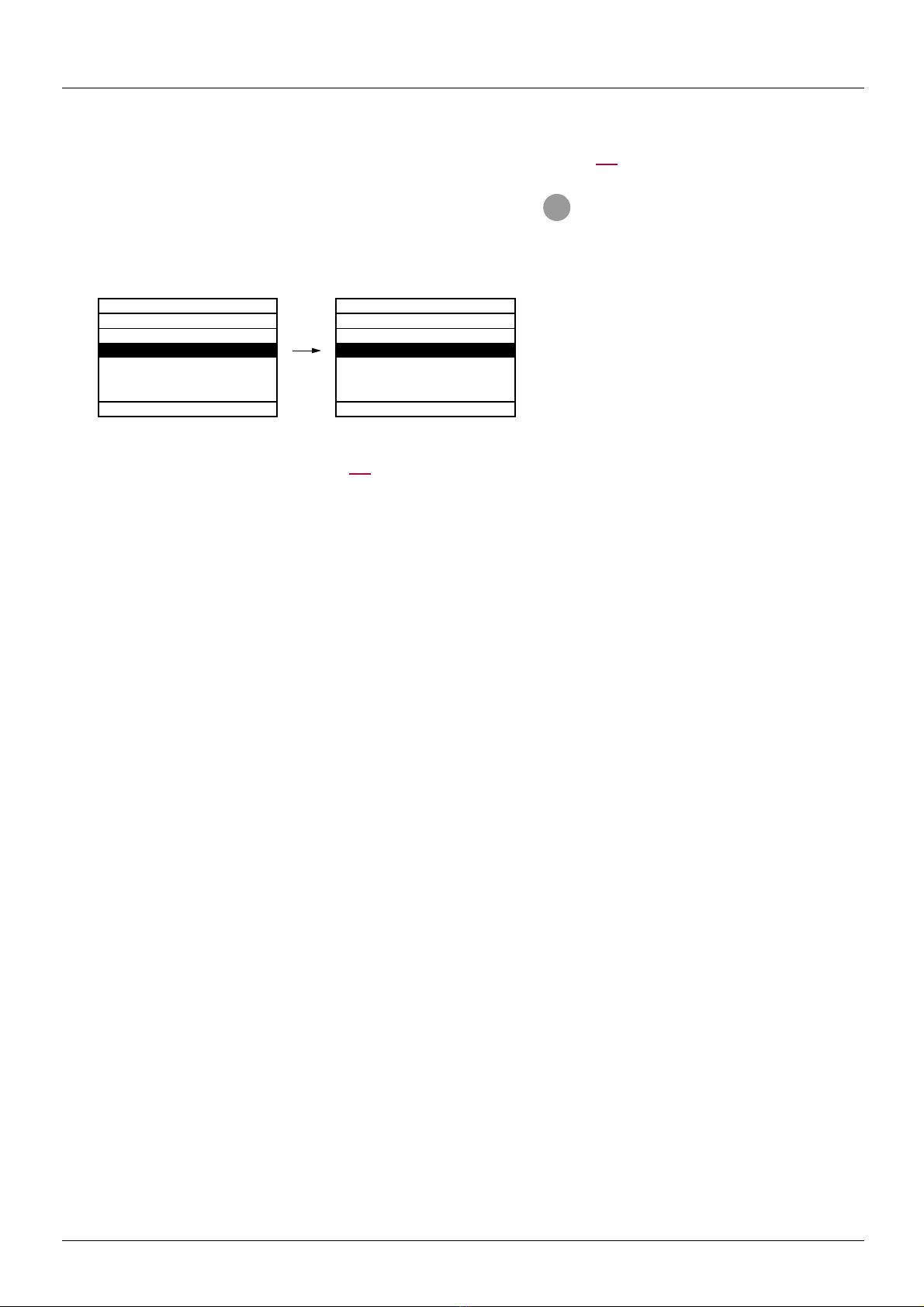
Finding a parameter in this document
F1
RDY Term +0.00Hz 0A
1.3 SETTINGS
Ramp increment: 01
Acceleration 9.51 s
Deceleration: 9.67 s
Acceleration 2: 12.58 s
Deceleration 2: 13.45 s
Code << >> Quick
Code
RDY Term +0.00Hz 0A
1.3 SETTINGS
Ramp increment: 01
ACC 9.51 s
Deceleration: 9.67 s
Acceleration 2: 12.58 s
Deceleration 2: 13.45 s
Code << >> Quick
The following assistance with finding explanations on a parameter is provided:
• With the integrated display terminal: Direct use of the parameter code index, page 277, to find the page giving details of the
displayed parameter.
• With the graphic display terminal: Select the required parameter and press : [Code]. The parameter code is displayed instead
of its name while the key is held down.
Example: ACC
Then use the parameter code index, page 277, to find the page giving details of the displayed parameter.
36 1755855 12/2009

[1.1 SIMPLY START] (SIM-)
RDY Term +0.00Hz 0A
MAIN MENU
1 DRIVE MENU
2 ACCESS LEVEL
3 OPEN / SAVE AS
4 PASSWORD
5 LANGUAGE
Code Quick
ENT
RDY Term +0.00Hz 0A
1 DRIVE MENU
1.1 SIMPLY START
1.2 MONITORING
1.3 SETTINGS
1.4 MOTOR CONTROL
1.5 INPUTS / OUTPUTS CFG
Code << >> Quick
ENT
RUN Term +50.00Hz 80A
1.1 SIMPLY START
2/3 wire control
Macro configuration
Customized macro
Standard mot. freq
Input phase loss
Code << >> Quick
XXX
SIM-
SUP-
ESC
ESC
ESC
ENT
ENT
ESC
LAC-
Displays the state of the drive
SIMPLY START
Power-up
With graphic display terminal:
With integrated display terminal:
The [1.1-SIMPLY START] (SIM-) menu can be used for fast startup, which is sufficient for the majority of applications.
The parameters in this menu can only be modified when the d rive is stopped a nd no run command is present, with the f ollowing exceptions:
• Auto-tuning, which causes the motor to start up
• The adjustment parameters on page 44
Note : The parameters of the [1.1 SIMPLY START] (SIM-) menu must be entered in the order in which they appear, as the later
ones are dependent on the first ones.
For example [2/3 wire control] (tCC) must be configured before any other parameters.
The [1.1 SIMPLY START] (SIM-) menu should be configured on its own or before the other drive configuration menus. If a modification
has previously been made to any of them, in particular in [1.4 MOTOR CONTROL] (drC-), some [1.1 SIMPLY START] (SIM-) parameters
may be changed, for example, the motor parameters, if a synchronous motor has been selected. Returning to the [1.1 SIMPLY START]
(SIM-) menu after modifying another drive configuration menu is unneces sary but does not pose any risk. Changes fol lowing modificat ion
of another configuration menu are not described, to avoid unnecessary complication in this section.
Macro configuration
Macro configuration provides a means of speeding up the configuration of functions for a specific field of application.
7 macro configurations are available:
• Start/stop (factory configuration)
• Handling
• General use
•Hoisting
• PID regulator
• Communication bus
•Master/slave
Selecting a macro configuration assigns the parameters in this macro configuration.
Each macro configuration can still be modified in the other menus.
1755855 12/2009 37

[1.1 SIMPLY START] (SIM-)
Macro configuration parameters
Assignment of the inputs/outputs
Input/
output
AI1 [Ref.1 channel] [Ref.1 channel] [Ref.1 channel] [Ref.1 channel] [Ref.1 channel]
AI2 [No] [Summing ref. 2] [Summing ref. 2] [No] [PID feedback] [No] [Torque
AO1 [No] [No] [No] [No] [No] [No] [No]
R1 [No drive flt] [No drive flt] [No drive flt] [No drive flt] [No drive flt] [No drive flt] [No drive flt]
R2 [No] [No] [No] [Brk control] [No] [No] [No]
LI1 (2-wire) [Forward] [Forward] [Forward] [Forward] [Forward] [Forward] [Forward]
LI2 (2-wire) [Reverse] [Reverse] [Reverse] [Reverse] [Reverse] [Reverse] [Reverse]
LI3 (2-wire) [No] [2 preset speeds] [Jog] [Fault reset] [PID integral
LI4 (2-wire) [No] [4 preset speeds] [Fault reset] [External fault] [2 preset PID
LI5 (2-wire) [No] [8 preset speeds] [Torque limitation] [No] [4 preset PID
LI6 (2-wire) [No] [Fault reset] [No] [No] [No] [No] [No]
LI1 (3-wire) Stop Stop Stop Stop Stop Stop Stop
LI2 (3-wire) [Forward] [Forward] [Forward] [Forward] [Forward] [Forward] [Forward]
LI3 (3-wire) [Reverse] [Reverse] [Reverse] [Reverse] [Reverse] [Reverse] [Reverse]
LI4 (3-wire) [No] [2 preset speeds] [Jog] [Fault reset] [PID integral
LI5 (3-wire) [No] [4 preset speeds] [Fault reset] [External fault] [2 preset PID
LI6 (3-wire) [No] [8 preset speeds] [Torque limitation] [No] [4 preset PID
LI7 to LI14 [No] [No] [No] [No] [No] [No] [No]
LO1 to LO4 [No] [No] [No] [No] [No] [No] [No]
R3/R4 [No] [No] [No] [No] [No] [No] [No]
AI3, AI4 [No] [No] [No] [No] [No] [No] [No]
RP [No] [No] [No] [No] [No] [No] [No]
AO2 [I motor] [I motor] [I motor] [I motor] [I motor] [I motor] [I motor]
AO3 [No] [Sign. torque] [No] [Sign. torque] [PID Output] [No] [Motor freq.]
F1 key [No] [No] [No] [No] [No] Control
F2, F3, F4
keys
[Start/Stop] [M. handling] [Gen. Use] [Hoisting] [PID regul.]
(PID reference)
reset]
ref.]
ref.]
reset]
ref.]
ref.]
Option cards
Graphic display terminal keys
[No] [No] [No] [No] [No] [No] [No]
[Network C.]
[Mast./
slave]
[Ref.2 channel]
([Ref.1 channel]
= integrated
Modbus) (1)
[Ref. 2
switching]
[Fault reset] [Fault reset]
[No] [No]
[Ref. 2
switching]
[Fault reset] [Fault reset]
[No] [No]
via graphic
display terminal
[Ref.1 channel]
reference]
[Trq/spd
switching]
[Trq/spd
switching]
[No]
In 3-wire control, the assignment of inputs LI1 to LI6 shifts.
(1) To start with integrated Modbus [Modbus Address] (Add) must first be configured, page 243.
Note: These assignments are reinitialized every time the macro configuration changes.
38 1755855 12/2009

[1.1 SIMPLY START] (SIM-)
Macro configuration parameters
Other configurations and settings
In addition to the assignment of inputs/outputs, other parameters are assigned only in the Hoisting and Mast./slave macro configurations.
Hoisting:
• [Movement type] (bSt) = [Hoisting] (UEr) page 161
• [Brake contact] (bCI) = [No] (nO) page 161
• [Brake impulse] (bIP) = [No] (nO) page 161
• [Brake release I FW] (Ibr) = [Rated mot. current] (nCr) page 161
• [Brake Release time] (brt) = 0.5 s page 162
• [Brake release freq] (bIr) = [Auto] (AUtO) page 162
• [Brake engage freq] (bEn) = [Auto] (AUto) page 162
• [Brake engage time] (bEt) = 0.5 s page 162
• [Engage at reversal] (bEd) = [No] (nO) page 163
• [Jump at reversal] (JdC) = [Auto] (AUtO) page 163
• [Time to restart] (ttr) = 0 s page163
• [Current ramp time] (brr) = 0 s page 165
• [Low speed] (LSP) = Rated motor slip calculated by the drive, page 44
• [Output Phase Loss] (OPL) = [Yes] (YES) page 224. No further modifications can be made to this parameter.
• [Catch on the fly] (FLr) = [No] (nO) page 222. No further modifications can be made to this parameter.
Mast./slave:
• [Motor control type] (Ctt) = [SVC I] (CUC) page 71
Note: These assignments are forced every time the macro configuration changes, except for [Motor control type] (Ctt) for the Mast./slave
macro configuration, if it is configured in [FVC] (FUC).
Return to factory settings:
Returning to factory settings with [Config. Source] (FCSI) = [Macro-Conf] (InI) page 250 will return the drive to the selected macro
configuration. The [Macro configuration] (CFG) parameter does not change, although [Customized macro] (CCFG) disappears.
Note :
• The factory settings that appear in the parameter tables correspond to [Macro con figuration] (CFG) = [Start/Stop] (StS).
This is the macro configuration set at the factory.
1755855 12/2009 39
[1.1 SIMPLY START] (SIM-)
UWV
L1 L3
ATV71H
KM10
R2A
R2C
L2
M
3
3
2
(1)
AI1
LI1 LI2+24
Electromagnetic brake
Forward
(Ascend)
Reverse
(Descend)
UWV
L1 L3
AI1
L2
M1
3
3
COMA01
LI1 LI2+24
COM AI2 UWV
LI1 +24
AI1
LI2
M2
3
LI3 L1 L3L2
3
ATV 71Hpppp
Slave drive
ATV 71H
pppp
Master drive
TorqueSpeed
ReverseForward
Reverse
Forward
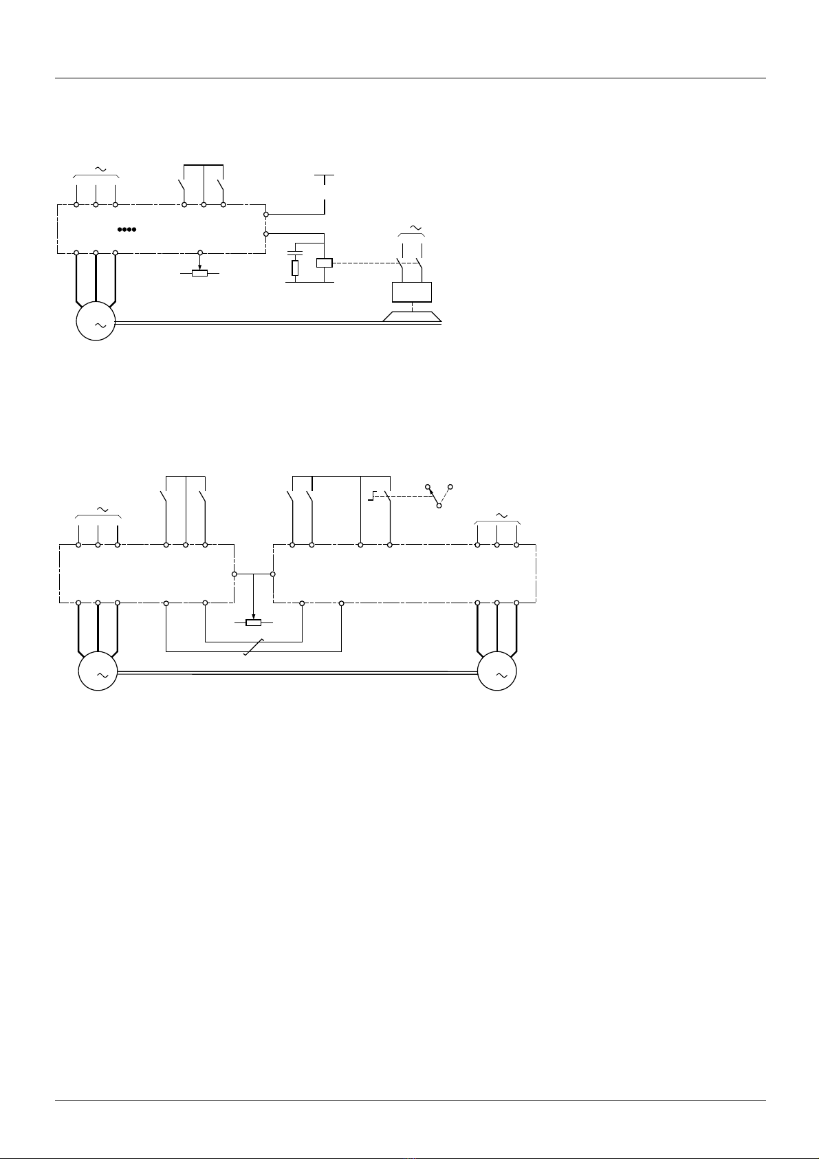
Example diagrams for use with the macro configurations
[Hoisting] (HSt) diagram
(1) A contact on the Preventa module must be inserted in the brake control circuit to engage it safely when the "Power Removal" safety
function is activated (see connection diagrams in the Installation Manual).
[Mast./slave] (MSL) diagram
When the two motors are mechanically connected, the Speed/torque contact closing results in operation in Mast./slave mode. The master
drive regulates the speed and controls the slave drive in torque mode to ensure distribution of the load.
40 1755855 12/2009

[1.1 SIMPLY START] (SIM-)
+24 LI1 LIx
ATV 71
+24 LI1 LI2 LIx
ATV 71
WARNING
UNINTENDED EQUIPMENT OPERATION
To change the assignment of [2/3 wire control] (tCC) press and hold down the “ENT” key for 2 s.
The following function will be returned to factory settings: [2 wire type] (tCt) page 89
as will all
functions which assign logic inputs.
The macro configuration selected will also be reset it if h as been customized (loss of custom settings).
Check that this change is compatible with the wiring diagram used.
Failure to follow these instructions can result in death or serious injury.
WARNING
UNINTENDED EQUIPMENT OPERATION
To change the assignment of [Macro configuration ] (CFG) press and hold down the “ENT” key for 2 s.
Check that the selected macro configuration is compatible with the wiring diagram used.
Failure to follow these instructions can result in death or serious injury.
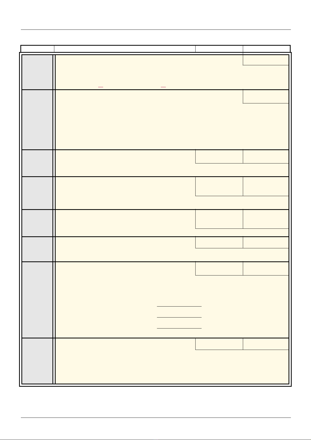
Code Name/Description Adjustment range Factory setting
tCC
M [2/3 wire control]
2C
3C
v [2 wire] (2C)
v [3 wire] (3C)
2-wire control: This is the input state (0 or 1) or edge (0 to 1 or 1 to 0), which controls running or stopping.
Example of "source" wiring:
3-wire control (pulse commands): A "forward" or "reverse" pulse is sufficient to command starting, a "stop"
pulse is sufficient to command stopping.
Example of "source" wiring:
[2 wire] (2C)
LI1: forward
LIx: reverse
LI1: stop
LI2: forward
LIx: reverse
1755855 12/2009 41
CFG
StS
HdG
HSt
GEn
PId
nEt
MSL
CCFG
YES
M [Macro configuration]
v [Start/Stop] (StS): Start/stop
v [M. handling] (HdG): Handling
v [Hoisting] (HSt): Hoisting
v [Gen. Use] (GEn): General use
v [PID regul.] (PId): PID regulation
v [Network C.] (nEt): Communication bus
v [Mast./slave] (MSL): Master/slave
M [Customized macro]
Read-only parameter, only visible if at least one macro configuration parameter has been modified.
v [Yes] (YES)
[Start/Stop] (StS)
[1.1 SIMPLY START] (SIM-)
100 - slip as a %
100
50 - slip in Hz
50
60 - slip in Hz
60
Code Name/Description Adjustment range Factory setting
bFr
IPL
YES
nPr
UnS
nCr
FrS
nSP
M [Standard mot. freq]
50
60
v [50Hz IEC] (50): IEC
v [60Hz NEMA] (60): NEMA
This parameter modifies the presets of the following parameters:[Rated mo tor volt.] (UnS) below, [High speed]
(HSP) page
M [Input phase loss]
nO
v [Ignore] (nO): Fault ignored, to be used when the drive is supplied via a single-phase supply or by the
DC
bus.
v [Freewheel] (YES): Fault, with freewheel stop.
If one phase disappears, the drive switches to fault mode [Input phase loss] (IPL), but if 2 or 3 phases
disappear, the drive continues to operate until it trips on an undervoltage fault.
This parameter is only accessible in this menu on ATV71H037M3 to HU75M3 drives (used with a single
phase supply).
M [Rated motor power]
Rated motor power given on the nameplate, in kW if [Standard mot. freq] (bFr) = [50Hz IEC] (50), in HP if
[Standard mot. freq] (bFr) = [60Hz NEMA] (60).
M [Rated motor volt.]
Rated motor voltage given on the nameplate.
ATV71pppM3: 100 to 240 V - ATV71pppN4: 200 to 480 V - ATV71pppY: 400 to 690 V
M [Rated mot. current]
Rated motor current given on the nameplate.
M [Rated motor freq.]
Rated motor frequency given on the nameplate.
The factory setting is 50 Hz, or preset to 60 Hz if [Standard mot. freq] (bFr) is set to 60 Hz.
M [Rated motor speed]
Rated motor speed given on the nameplate.
0 to 9999 rpm then 10.00 to 60.00 krpm on the integrated display terminal.
If, rather than the rated speed, the nameplate indicates the synchronous speed and the slip in Hz or as a %,
calculate the rated speed as follows:
[50Hz IEC] (50)
44, [Freq. threshold] (Ftd) page 67, [Rated motor freq.] (FrS) and [Max frequency] (tFr) .
According to drive
rating
According to drive
rating
According to drive
rating
0.25 to 1.5 In (1) According to drive
10 to 500 Hz 50 Hz
0 to 60000 RPM According to drive
According to drive
rating
According to drive
rating and [Standard
mot. freq] (bFr)
rating and [Standard
mot. freq] (bFr)
rating
• Nominal speed = Synchronous speed x
or
• Nominal speed = Synchronous speed x (50 Hz motors)
or
• Nominal speed = Synchronous speed x (60 Hz motors)
tFr
(1)In corresponds to the rated drive current indicated in the Installation Manual and on the drive nameplate.
42 1755855 12/2009
M [Max frequency]
The factory setting is 60 Hz, or preset to 72 Hz if [Standard mot. freq] (bFr) is set to 60 Hz.
The maximum value is limited by the following conditions:
• It must not exceed 10 times the value of [Rated motor freq.] (FrS)
• It must not exceed 500 Hz for ATV71pppY drives or those rated higher than ATV71HD37 (values between
500 Hz and 1600
Hz are only possible for powers limited to 37 kW (50 HP).
10 to 1600 Hz 60 Hz

[1.1 SIMPLY START] (SIM-)
Code Name/Description Factory setting
tUn
dOnE
tUS
PEnd
PrOG
FAIL
dOnE
PHr
nO
YES
tAb
AbC
ACb
M [Auto tuning]
[No] (nO)
v [No] (nO): Auto-tuning not performed.
v [Yes] (YES): Auto-tuning is performed as soon as possible, then the parameter automatically changes to [Done]
(dOnE).
v [Done] (dOnE) : Use of the values given the last time auto-tuning was performed.
Caution:
• It is essential that all motor parameters ([Rated motor volt.] (UnS), [Rated motor freq.] (FrS), [Rated mot.
current] (nCr), [Rated motor speed] (nSP), [Rated motor power] (nPr)) are configured correctly before
starting auto-tuning.
If at least one of these parameters is modified after auto-t uning has been performed, [Auto tuning] (tUn ) will
return to [No] (nO) and must be repeated.
• Auto-tuning is only performed if no stop command has been activated. If a "freewheel stop" or "fast stop"
function has been assigned to a logic input, this input must be set to 1 (active at 0).
• Auto-tuning takes priority over any run or prefluxing commands, which will be taken into account after the
auto-tuning sequence.
• If auto-tuning fails, the drive displays [No] (nO) and, depending on the configuration of [Autotune faul t mgt]
(tnL) page
• Auto-tuning may last for 1 to 2 seconds. Do not interrupt the process. Wait for the display to change to
"[Done] (dOnE)" or "[No] (nO)".
238, may switch to [Auto-tuning] (tnF) fault mode.
Note: During auto-tuning the motor operates at rated current.
M [Auto tuning status]
(for information only, cannot be modified)
[Not done] (tAb)
v [Not done] (tAb): The default stator resistance value is used to control the motor.
v [Pending] (PEnd): Auto-tuning has been requested but not yet performed.
v [In Progress] (PrOG): Auto-tuning in progress.
v [Failed] (FAIL): Auto-tuning has failed.
v [Done] (dOnE) : The stator resistance measured by the auto-tuning function is used to control the motor.
M [Output Ph rotation]
[ABC] (AbC)
v [ABC] (AbC): Forward
v [ACB] (ACb): Reverse
This parameter can be used to reverse the direction of rotation of the motor without reversing the wiring.
1755855 12/2009 43
[1.1 SIMPLY START] (SIM-)
Parameters that can be changed during operation or when stopped
Code Name/Description Factory setting
ItH
ACC
dEC
LSP
HSP
(1)In corresponds to the rated drive current indicated in the Installation Manual and on the drive nameplate.
M [Mot. therm. current]
Motor thermal protection current, to be set to the rated current indicated on the nameplate.
M [Acceleration]
Time to accelerate from 0 to the [Rated motor freq.] (FrS) (page 42). Make sure that this value is compatible
with the inertia being driven.
M [Deceleration]
Time to decelerate from the [Rated motor freq.] (FrS) (page 42) to 0. Make sure that this value is compatible
with the inertia being driven.
M [Low speed]
Motor frequency at minimum reference, can be set between 0 and [High speed] (HSP).
M [High speed]
Motor frequency at maximum reference, can be set bet ween [Low speed] (LSP) and [Max frequency] (tFr). The
factory setting changes to 60 Hz if [Standard mot. freq] (bFr) = [60Hz NEMA] (60).
0.2 to 1.5 In (1) According to drive
0.1 to 999.9 s 3.0 s
0.1 to 999.9 s 3.0 s
rating
0
50 Hz
44 1755855 12/2009

[1.2 MONITORING] (SUP-)
RDY Term +0.00Hz 0A
MAIN MENU
1 DRIVE MENU
2 ACCESS LEVEL
3 OPEN / SAVE AS
4 PASSWORD
5 LANGUAGE
Code Quick
ENT
RDY Term +0.00Hz 0A
1 DRIVE MENU
1.1 SIMPLY START
1.2 MONITORING
1.3 SETTINGS
1.4 MOTOR CONTROL
1.5 INPUTS / OUTPUTS CFG
Code << >> Quick
ENT
RUN Term +50.00 Hz 80A
1.2 MONITORING
I/O MAP
PROG. CARD I/O MAP
COMMUNICATION MAP
Alarm groups :
HMI Frequency ref. :
Code << >> Quick
XXX
SIM-
SEt-
SUP-
ESC
ESC
ESC
ESC
ENT
ENT
ESC
LAC-
Displays the state of the drive
MONITORING
Power-up
With graphic display terminal:
With integrated display terminal:
1755855 12/2009 45

[1.2 MONITORING] (SUP-)
I/O
I/O of the Controller Inside card if it is present
Communication data and values
Drive internal drive states and values (see page 51
)
ENT
ENT
ENT
ENT
1
0
1
0
With graphic display terminal
This menu can be used to display the inputs/outputs, the drive internal states and values, and the communication data and values.
RUN Term +50.00Hz 80A
I/O MAP
PROG. CARD I/O MAP
COMMUNICATION MAP
Alarm groups:
HMI Frequency ref.:
1.2 MONITORING
Code << >> Quick
I/O
RUN Term +50.00Hz 80A
LOGIC INPUT MAP
ANALOG INPUTS IMAGE
LOGIC OUTPUT MAP
ANALOG OUTPUTS IMAGE
FREQ. SIGNAL IMAGE
Code Quick
State 0
State 1
RUN Term +50.00Hz 80A
LOGIC INPUT MAP LI1 assignment
PR LI1 LI2 LI3 LI4 LI5 LI6 LI7 Forward
LI8 LI9 LI10 LI11 LI12 LI13 LI14 LI1 On Delay : 0 ms
<< >> Quick << >> Quick
I/O MAP
Move from one screen to another
(from LOGIC INPUT MAP
to FREQ. SIGNAL IMAGE)
by turning the navigation button
Access to the selected input or
output configuration:
Press ENT.
RUN Term +50.00Hz 80A
Pre Fluxing
State 0
State 1
RUN Term +50.00Hz 80A RUN Term +50.00Hz 80A
ANALOG INPUTS IMAGE AI1 assignment
AI1 : 9.87 V Ref.1 channel
AI2 : 2.35 mA Forced local
Torque reference
AI1 min value : 0.0 V
AI1 max value : 10.0 V
Code << >> Quick Quick
RUN Term +50.00Hz 80A RUN Term +50.00Hz 80A
LOGIC OUTPUT MAP LO1 assignment
R1 R2 LO No
LO1 delay time : 0 ms
LO1 active at : 1
LOA: 0000000000000010b LO1 holding time : 0 ms
<< >> Quick << >> Quick
RUN Term +50.00Hz 80A RUN Term +50.00Hz 80A
ANALOG OUTPUTS IMAGE AO1 assignment
AO1 : 9.87 V Motor freq.
AO1 min output : 4 mA
AO1 max output : 20 mA
AO1 Filter : 10 ms
Code << >> Quick Quick
RUN Term +50.00Hz 80A RUN Term +50.00Hz 80A
FREQ. SIGNAL IMAGE RP assignment
RP input : 25.45 kHz Frequency ref.
Encoder : 225 kHz RP min value : 2 kHz
RP max value : 50 kHz
RP filter : 0 ms
Code << >> Quick Quick
46 1755855 12/2009

[1.2 MONITORING] (SUP-)
ENT
ENT
1
0
1
0
1
0
With graphic display terminal
Controller Inside card I/O
State 0
State 1
State 0
State 1
RUN Term +50.00Hz 80A
PROG. CARD I/O MAP
PROG CARD LI MAP
PROG. CARD AI MAP
PROG CARD LO MAP
PROG. CARD AO MAP
Code Quick
RUN Term +50.00Hz 80A
PROG CARD LI MAP
LI51 LI52 LI53 LI54 LI55 LI56 LI57 LI58
LI59 LI60
<< >> Quick
RUN Term +50.00Hz 80A RUN Term +50.00Hz 80A
PROG CARD AI MAP AI51
AI51 : 0.000 mA
AI52 : 9.87 V
Move from one screen to another
(from PROG CARD LI MAP
to PROG. CARD AO MAP)
by turning the navigation button
0 mA
Code << >> Quick << >> Quick
RUN Term +50.00Hz 80A
PROG CARD LO MAP
LO51 LO52 LO53 LO54 LO55 LO56
Min = 0.001 Max = 20,000
<< >> Quick
RUN Term +50.00Hz 80A RUN Term +50.00Hz 80A
PROG. CARD AO MAP AO51
AO51 : 0.000 mA
AO52 : 9.87 V
0 mA
Code << >> Quick << >> Quick
Min = 0.001 Max = 20,000
1755855 12/2009 47

[1.2 MONITORING] (SUP-)
RUN Term +50.00Hz 80A
COMMUNICATION MAP
Command Channel : Modbus
Cmd value : ABCD Hex
Active ref. channel: CANopen
Frequency ref. : -12.5 Hz
ETA state word: 2153 Hex
Code Quick
W3141 : F230 Hex
W2050 : F230 Hex
W4325 : F230 Hex
W0894 : F230 Hex
COM. SCANNER INPUT MAP
COM SCAN OUTPUT MAP
CMD. WORD IMAGE
FREQ. REF. WORD MAP
MODBUS NETWORK DIAG
MODBUS HMI DIAG
CANopen MAP
PROG. CARD SCANNER
RUN Term +50.00Hz 80A
COM. SCANNER INPUT MAP
Com Scan In1 val.: 0
Com Scan In2 val.: 0
Com Scan In3 val.: 0
Com Scan In4 val.: 0
Com Scan In5 val.: 0
Code Quick
Com Scan In6 val.: 0
Com Scan In7 val.: 0
Com Scan In8 val.: 0
RUN Term +50.00Hz 80A
COM SCAN OUTPUT MAP
Com Scan Out1 val.: 0
Com Scan Out2 val.: 0
Com Scan Out3 val.: 0
Com Scan Out4 val.: 0
Com Scan Out5 val.: 0
Code Quick
Com Scan Out6 val.: 0
Com Scan Out7 val.: 0
Com Scan Out8 val.: 0
RUN Term +50.00Hz 80A
CMD. WORD IMAGE
Modbus cmd.: 0000 Hex.
CANopen cmd.: 0000 Hex.
COM. card cmd. : 0000 Hex.
Prog. card cmd: 0000 Hex.
Code Quick
RUN Term +50.00Hz 80A
FREQ. REF. WORD MAP
Ref. Modbus: 0.0 Hz
Ref. CANopen: 0.0 Hz
Com. card ref. : 0.0 Hz
Prog. Card ref: 0.0 Hz
Code Quick
With graphic display terminal
Communication
[COMMUNICATION MAP] indicates the types of bus used for control or reference, the
corresponding command and reference values, the status word, the words selected in
the [DISPLAY CONFIG.] menu, etc.
The display format (hexadecimal or decimal) can be configured in the [DISPLAY
CONFIG.] menu.
[COM. SCANNER INPUT MAP] and [COM SCAN OUTPUT MAP]:
Visualization of registers exchanged periodically (8 input and 8 output) for integrated Modbus and for fieldbus cards.
48 1755855 12/2009
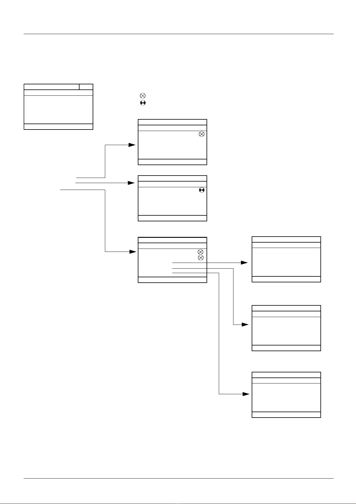
[1.2 MONITORING] (SUP-)
RUN Term +50.00Hz 80A
COMMUNICATION MAP
Command Channel : Modbus
Cmd value : ABCD Hex
Active ref. channel: CANopen
Frequency ref. : -12.5 Hz
ETA state word: 2153 Hex
Code Quick
W3141 : F230 Hex
W2050 : F230 Hex
W4325 : F230 Hex
W0894 : F230 Hex
COM. SCANNER INPUT MAP
COM SCAN OUTPUT MAP
CMD. WORD IMAGE
FREQ. REF. WORD MAP
MODBUS NETWORK DIAG
MODBUS HMI DIAG
CANopen MAP
PROG. CARD SCANNER
Communication via Modbus
RUN Term +50.00Hz 80A
MODBUS NETWORK DIAG
COM LED :
Mb NET frames nb.
Mb NET CRC errors
Code Quick
Communication via the graphic display terminal
RUN Term +50.00Hz 80A
MODBUS HMI DIAG
COM LED :
Mb HMI frames nb.
Mb HMI CRC errors
Code Quick
PDO configuration using
the network tool.
Some PDOs cannot be
used.
RUN Term +50.00Hz 80A
PDO1 IMAGE
Received PDO1-1 : FDBA Hex
Received PDO1-2
Received PDO1-3
Received PDO1-4
Transmit PDO1-1 : FDBA Hex
Code Quick
Transmit PDO1-2
Transmit PDO1-3
Transmit PDO1-4
RUN Term +50.00Hz 80A
PDO2 IMAGE
Received PDO2-1 : FDBA Hex
Received PDO2-2
Received PDO2-3
Received PDO2-4
Transmit PDO2-1 : FDBA Hex
Code Quick
Transmit PDO2-2
Transmit PDO2-3
Transmit PDO2-4
RUN Term +50.00Hz 80A
PDO3 IMAGE
Received PDO3-1 : FDBA Hex
Received PDO3-2
Received PDO3-3
Received PDO3-4
Transmit PDO3-1 : FDBA Hex
Code Quick
Transmit PDO3-2
Transmit PDO3-3
Transmit PDO3-4
Communication via CANopen
PDO images are only visible if
CANopen has been enabled
(address other than OFF) and if
the PDOs are active.
RUN Term +50.00Hz 80A
CANopen MAP
RUN LED:
ERR LED:
PDO1 IMAGE
PDO2 IMAGE
PDO3 IMAGE
Code Quick
Canopen NMT state
Number of TX PDO 0
Number of RX PDO 0
Error code 0
RX Error Counter 0
TX Error Counter 0
With graphic display terminal
Communication (continued)
The state of the LEDs, the periodic data, the address, the speed, and the
format, etc,. is given for each bus.
LED off
LED on
1755855 12/2009 49

[1.2 MONITORING] (SUP-)
RUN Term +50.00Hz 80A
COMMUNICATION MAP
Command Channel : Modbus
Cmd value : ABCD Hex
Active ref. channel: CANopen
Frequency ref. : -12.5 Hz
ETA state word: 2153 Hex
Code Quick
W3141 : F230 Hex
W2050 : F230 Hex
W4325 : F230 Hex
W0894 : F230 Hex
COM. SCANNER INPUT MAP
COM SCAN OUTPUT MAP
CMD. WORD IMAGE
FREQ. REF. WORD MAP
MODBUS NETWORK DIAG
MODBUS HMI DIAG
CANopen MAP
PROG. CARD SCANNER
Controller Inside card
RUN Term +50.00Hz 80A
PROG. CARD SCANNER
Input scanner
Output scanner
Code Quick
RUN Term +50.00Hz 80A
Input scanner
Prg.card. scan in1: 0
Prg.card. scan in2: 0
Prg.card. scan in3: 0
Prg.card. scan in4: 0
Prg.card. scan in5: 0
Code Quick
Prg.card scan in6: 0
Prg.card scan in7: 0
Prg.card scan in8: 0
RUN Term +50.00Hz 80A
Output scanner
PLC card.scan Out1: 0
PLC card.scan Out2: 0
PLC card.scan Out3: 0
PLC card.scan Out4: 0
PLC card.scan Out5 : 0
Code Quick
PLC card.scan Out6: 0
PLC card.scan Out7: 0
PLC card.scan Out8: 0
With graphic display terminal
Communication (continued)
[Input scanner] and [Output scanner]:
Visualization of registers exchanged periodically (8 input and 8 output).
50 1755855 12/2009

[1.2 MONITORING] (SUP-)
With graphic display terminal: Drive-internal states and values
Name/Description
[Alarm groups] (ALGr)
[HMI Frequency ref.] (LFr)
[Internal PID ref.] (rPI)
[HMI torque ref.] (Ltr)
[Multiplying coeff.] (MFr)
[Frequency ref.] (FrH)
[Torque reference] (trr)
[Output frequency] (rFr)
[Measured output fr.] (MMF)
[Pulse in. work. freq.] (FqS)
[Motor current] (LCr)
[ENA avg speed] (AUS)
[Motor speed] (SPd)
[Motor voltage] (UOP)
[Motor power] (OPr)
[Motor torque] (Otr)
[Mains voltage] (ULn)
[Motor thermal state] (tHr)
[Drv.thermal state] (tHd)
[DBR thermal state] (tHb)
[Consumption] (APH)
[Run time] (rtH)
[Power on time] (PtH)
[IGBT alarm counter] (tAC)
[PID reference] (rPC)
[PID feedback] (rPF)
[PID error] (rPE)
[PID Output] (rPO)
[Date/Time] (CLO)
[- - - - -] (o02)
to
[- - - - -] (o06)
[Config. active] (CnFS)
[Utilised param. set] (CFPS)
[ALARMS] (ALr-)
[OTHER STATE] (SSt-)
Current alarm group numbers
in Hz. Frequency reference via the graphic display terminal (can be accessed if the function has been
configured).
as a process value. PID reference via graphic display terminal (can be accessed if the function has been
configured).
as a % of the rated torque. Torque reference via graphic display terminal.
as a % (can be accessed if [Multiplier ref. -] (MA2,MA3) page 136 has been assigned)
in Hz
as a % of the rated torque (can be accessed if the function has been configured)
in Hz
in Hz: The measured motor speed is displayed if an encoder card has been inserted, oth erwise 0 appears.
in Hz: Frequency of the "Pulse input" input used by the [FREQUENCY METER] (FqF-) function, page 235.
in A
in Hz: The parameter can be accessed if [ENA system] (EnA) = [Yes] (YES) (see page 81)
in rpm
in V
as a % of the rated power
as a % of the rated torque
in V. Line voltage from the point of view of the DC bus, motor running or stopped.
as a %
as a %
as a % (can only be accessed on high rating drives)
in Wh, kWh or MWh (accumulated consumption)
in seconds, minutes or hours (length of time the motor has been switched on)
in seconds, minutes or hours (length of time the drive has been switched on)
in seconds (length of time the "IGBT temperature" alarm has been active)
as a process value (can be accessed if the PID function has been configured)
as a process value (can be accessed if the PID function has been configured)
as a process value (can be accessed if the PID function has been configured)
in Hz (can be accessed if the PID function has been configured)
Current date and time generated by the Controller Inside card (can be accessed if the card has been
inserted)
Words generated by the Controller Inside card (can be accessed if the card has been inserted)
Active configuration [Config. n°0, 1 or 2]
[Set n°1, 2 or 3] (can be accessed if parameter switching has been enabled, see page 199)
List of current alarms. If an alarm is present, a appears.
List of secondary states:
- [In motor fluxing] (FLX): In motor fluxing
- [PTC1 alarm] (PtC1): Probe alarm 1
- [PTC2 alarm] (PtC2): Probe alarm 2
- [LI6=PTC alarm] (PtC3): LI6 = PTC probe alarm
- [Fast stop in prog.] (FSt): Fast stop in progress
- [Current Th. attained] (CtA): Current threshold
attained ([Current threshold] (Ctd) page
- [Freq. Th. attained] (FtA): Frequency threshold
attained ([Freq. threshold] (Ftd) page
- [Freq. Th. 2 attained] (F2A): 2nd frequency threshold
attained ([Freq. threshold 2] (F2d) page
- [Frequency ref. att.] (SrA): Frequency reference
attained
- [Motor th. state att.] (tSA): Motor 1 thermal state
attained
- [External fault alarm] (EtF): External fault alarm
- [Auto restart] (AUtO): Automatic restart i n p rogress
- [Remote] (FtL) : Line mode control
- [Auto-tuning] (tUn): Performing auto-tuning
- [Undervoltage] (USA): Undervoltage alarm
- [Cnfg.1 act.] (CnF1): Configuration 1 active
- [Cnfg.2 act.] (CnF2): Configuration 2 active
66)
67)
67)
- [HSP attained] (FLA): High speed attained
- [Load slipping] (AnA): Slipping alarm
- [Set 1 active] (CFP1): Parameter set 1
- [Set 2 active] (CFP2): Parameter set 2
- [Set 3 active] (CFP3): Parameter set 3
- [In braking] (brS): Drive braking
- [DC bus loading] (dbL): DC bus loading
- [Forward] (MFrd): Motor running forward
- [Reverse] (MrrS): Motor running in reverse
- [High torque alarm] (ttHA): Motor torque
- [Low torque alarm] (ttLA): Motor torque
- [Freq. meter Alarm] (FqLA): Measured
active
active
active
overshooting high threshold [High torque
thd.] (ttH) page
undershooting low threshold [Low torque
thd.] (ttL) page
speed threshold attained: [Pulse warning
thd.] (FqL) page
66.
66.
67.
1755855 12/2009 51

[1.2 MONITORING] (SUP-)
State 1
State 0
LI1 LI2 LI3 LI4 LI5 LI6 LI7 LI8
State 1
State 0
LI9 LI10 LI11 LI12 LI13 LI14 PR
With integrated display terminal
This menu can be used to display the drive inputs, states and internal values.
Code Name/Description Adjustment range Factory setting
IOM-
LIA-
L1A
to
L14A
LIS1
LIS2
I/O MAP
b Logic input functions
Can be used to display the functions assigned to each input. If no functions have been assigned, nO is
displayed.
Use the and arrows to scroll through the functions. If a number of functions have been assigned
to the same input, check that they are compatible.
b State of logic inputs LI1 to LI8
Can be used to visualize the state of logic inputs LI1 to LI8
(display segment assignment: high = 1, low = 0)
Example above: LI1 and LI6 are at 1; LI2 to LI5, LI7 and LI8 are at 0.
b State of logic inputs LI9 to LI14 and Power Removal
Can be used to visualize the state of logic inputs LI9 to LI14 and PR (Power Removal)
(display segment assignment: high = 1, low = 0)
AIA-
AI1A
AI2A
AI3A
AI4A
Example above: LI9 and LI14 are at 1, LI10 to LI13 are at 0 and PR (Power Removal) is at 1.
b Analog input functions
Can be used to display the functions assigned to each input. If no functions have been assigned, nO is
displayed. Use the
assigned to the same input, check that they are compatible.
and arrows to scroll through the functions. If a number of functio ns have been
52 1755855 12/2009

[1.2 MONITORING] (SUP-)
With integrated display terminal: Drive-internal states and values
Code Name/Description Unit
ALGr
rPI
MFr
FrH
trr
rFr
MMF
FqS
LCr
AUS
SPd
UOP
OPr
Otr
ULn
tHr
tHd
tHb
APH
rtH
PtH
tAC
rPC
rPF
rPE
rPO
CLO-
o02
o03
o04
o05
o06
CnFS
CFPS
Alarm groups: Current alarm group numbers
Internal PID reference: PID reference via graphic display terminal (can be accessed if the func tion has been
configured).
Multiplication coefficient (can be accessed if [Multiplier ref. -] (MA2,MA3) page 136 has been assigned) %
Frequency ref. Hz
Torque reference: Can be accessed if the function has been configured %.
Output frequency Hz
The measured motor speed is displayed if an encoder card has been inserted, otherwise 0 appears. Hz
Frequency of the "Pulse input" input used by the [FREQUENCY METER] (FqF-) function, page 235. Hz
Motor current A
ENA avg SPEED: The parameter can be accessed if EnA = YES (see page 81) Hz
Motor speed rpm
Motor voltage V
Motor power %
Motor torque %
Line voltage: Line voltage from the point of view of the DC bus, motor running or stopped. V
Motor thermal state %
Drv thermal state %
DBR thermal state: Can be accessed on high rating drives only. %
Power consumption Wh, kWh or
Run time: Length of time the motor has been turned on seconds,
Power on time: Length of time the drive has been turned on
IGBT alarm counter: Length of time the "IGBT temperature" alarm has been active seconds
PID reference: Can be accessed if the PID function has been configured as a process
PID feedback: Can be accessed if the PID function has been configured
PID error: Can be accessed if the PID function has been configured
PID Output: Can be accessed if the PID function has been configured Hz
tIME, dAY: Current date and time generated by the Controller Inside card (can be accessed if the card has
been inserted)
Word generated by the Controller Inside card (can be accessed if the card has been inserted)
Word generated by the Controller Inside card (can be accessed if the card has been inserted)
Word generated by the Controller Inside card (can be accessed if the card has been inserted)
Word generated by the Controller Inside card (can be accessed if the card has been inserted)
Word generated by the Controller Inside card (can be accessed if the card has been inserted)
Config. active: CnF0, 1 or 2 (can be accessed if motor or configuration switching has been enabled, see
page
204)
Utilised param. set: CFP1, 2 or 3 (can be accessed if parameter switching has been enabled, see page 199)
as a process
value
MWh
minutes or
hours
value
1755855 12/2009 53

[1.3 SETTINGS] (SEt-)
RDY Term +0.00Hz 0A
MAIN MENU
1 DRIVE MENU
2 ACCESS LEVEL
3 OPEN / SAVE AS
4 PASSWORD
5 LANGUAGE
Code Quick
ENT
RDY Term +0.00Hz 0A
1 DRIVE MENU
1.1 SIMPLY START
1.2 MONITORING
1.3 SETTINGS
1.4 MOTOR CONTROL
1.5 INPUTS / OUTPUTS CFG
Code << >> Quick
ENT
RUN Term +50.00Hz 80A
1.3 SETTINGS
Ramp increment
Acceleration
Deceleration
Acceleration 2
Deceleration 2
Code << >> Quick
XXX
SIM-
SEt-
ESC
ESC
ESC
ESC
ENT
ENT
ESC
LAC-
drC-
Displays the state of the drive
ADJUST
Power-up
With graphic display terminal:
With integrated display terminal:
54 1755855 12/2009

[1.3 SETTINGS] (SEt-)
DANGER
UNINTENDED EQUIPMENT OPERATION
• Check that changes made to the settings during operation do not present any danger.
• We recommend stopping the drive before making any changes.
Failure to follow these instructions will result in death or serious injury.
The adjustment parameters can be modified with the drive running or stopped.
Code Name/Description Adjustment range Factory setting
Inr
0.01
ACC
dEC
AC2
g
dE2
g
tA1
g
tA2
g
tA3
g
0.1
M [Ramp increment]
v [0,01]: ramp up to 99.99 seconds
v [0,1]: ramp up to 999.9 seconds
1
v [1]: ramp up to 6000 seconds
This parameter is valid for [Acceleration] (ACC), [Deceleration] (dEC), [Acceleration 2] (AC2) and [Deceleration
2] (dE2).
M [Acceleration]
Time to accelerate from 0 to the [Rated motor freq.] (FrS) (page 69). Make sure that this value is compatible
with the inertia being driven.
M [Deceleration]
Time to decelerate from the [Rated motor freq.] (FrS) (page 69) to 0. Make sure that this value is compatible
with the inertia being driven.
M [Acceleration 2]
See page 139
Time to accelerate from 0 to the [Rated motor freq.] (FrS). Make sure that this value is compatible with the
inertia being driven.
M [Deceleration 2]
See page 139
Time to decelerate from the [Rated motor freq.] (FrS) to 0. Make sure that this value is compatible with the
inertia being driven.
M [Begin Acc round]
See page 138
Rounding of start of acceleration ramp as a % of the [Acceleration] (ACC) or [Acceleration 2] (AC2) ramp time.
M [End Acc round]
See page 138
- Rounding of end of acceleration ramp as a % of the [Acceleration] (ACC) or [Acceleration 2] (AC2) ramp
time.
- Can be set between 0 and (100% - [Begin Acc round] (tA1))
M Begin Dec round]
See page 138
Rounding of start of deceleration ramp as a % of the [Deceleration] (dEC) or [Deceleration 2] (dE2) ramp time.
0,01 - 0,1 - 1 0,1
0.01 to 6000 s (1) 3.0 s
0.01 to 6000 s (1) 3.0 s
0.01 to 6000 s (1) 5.0 s
0.01 to 6000 s (1) 5.0 s
0 to 100% 10%
10%
0 to 100% 10%
(1)Range 0.01 to 99.99 s or 0.1 to 999.9 s or 1 to 6000 s according to [Ramp increment] (Inr).
These parameters only appear if the corresponding function has been selected in another menu. When the parameters can
g
also be accessed and adjusted from within the confi guration menu for t he correspondin g function, thei r description is deta iled
in these menus, on the pages indicated, to aid progra mming.
1755855 12/2009 55
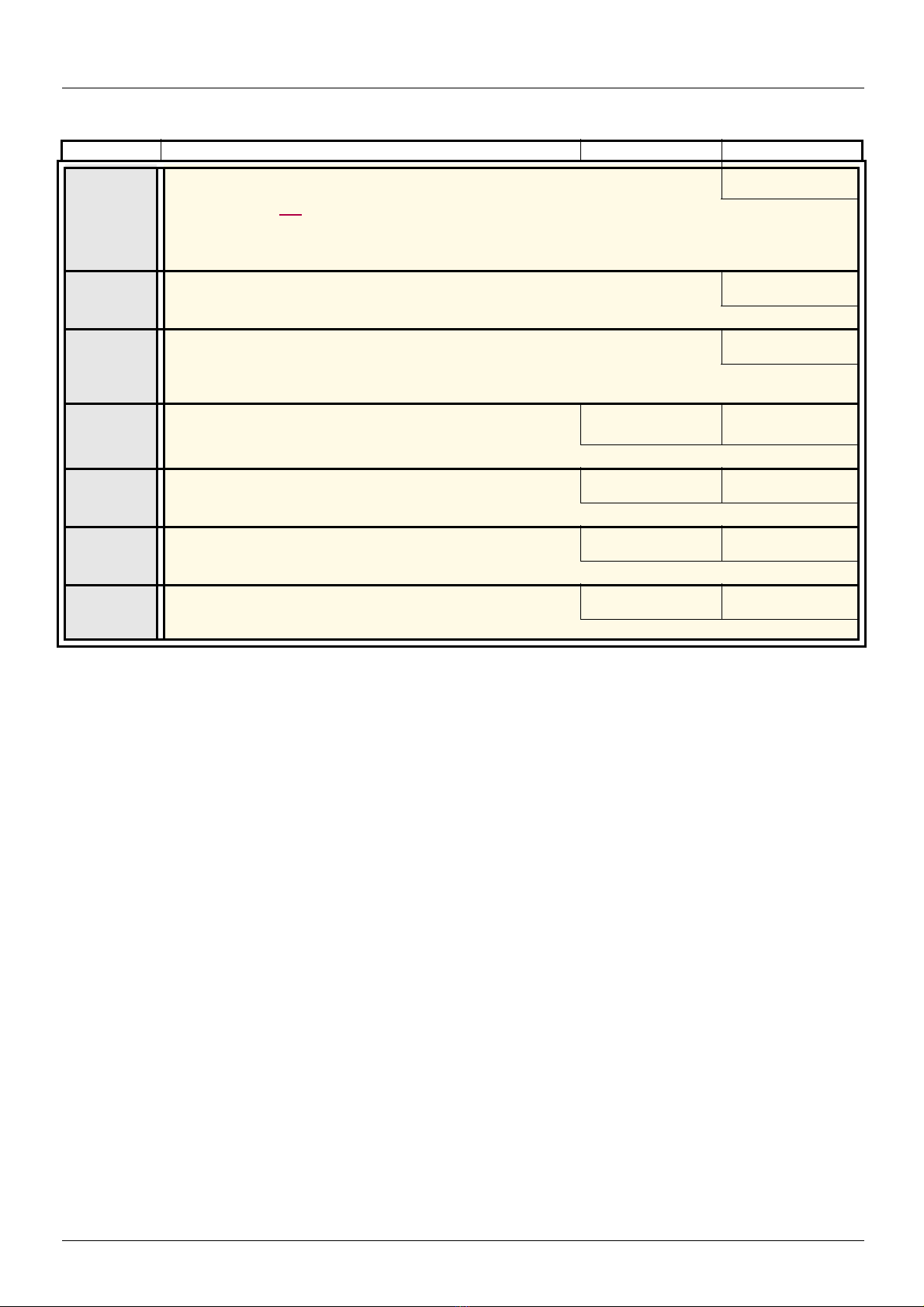
[1.3 SETTINGS] (SEt-)
Code Name/Description Adjustment range Factory setting
tA4
g
M [End Dec round]
See page 138
- Rounding of end of deceleration ramp as a % of the [Deceleration] (dEC) or [Deceleration 2] (dE2) ramp
time.
- Can be set between 0 and (100% - [Begin Dec round] (tA3))
10%
LSP
HSP
ItH
SPG
SIt
SFC
(1)In corresponds to the rated drive current indicated in the Installation Manual or on the drive nameplate.
M [Low speed]
Motor frequency at minimum reference, can be set between 0 and [High speed] (HSP).
M [High speed]
Motor frequency at maximum reference, can be set bet ween [Low speed] (LSP) and [Max frequency] (tFr). The
factory setting changes to 60 Hz if [Standard mot. freq] (bFr) = [60Hz NEMA] (60).
M [Mot. therm. current]
Motor thermal protection current, to be set to the rated current indicated on the nameplate.
M [Speed prop. gain]
Speed loop proportional gain
M [Speed time integral]
Speed loop integral time constant.
M [K speed loop filter]
Speed loop filter coefficient.
0.2 to 1.5 In (1) According to drive
0 to 1000% 40%
1 to 1000% 100%
0 to 100 0
0 Hz
50 Hz
rating
56 1755855 12/2009

[1.3 SETTINGS] (SEt-)
0 50045040035030025020015010050
0
1
0,8
0,6
0,4
0,2
Reference division
Time in ms
0 50045040035030025020015010050
0
1
0,8
0,6
0,4
0,2
Reference division
Time in ms
0 50045040035030025020015010050
0
1
0,8
0,6
0,4
0,2
Reference division
Time in ms
0 50045040035030025020015010050
0
1
0,8
0,6
0,4
0,2
Reference division
Time in ms
0 50045040035030025020015010050
0
1
0,8
0,6
0,4
0,2
Reference division
Time in ms
0 50045040035030025020015010050
0
1
0,8
0,6
0,4
0,2
Reference division
Time in ms
Parameter settings for [K speed loop filter] (SFC), [Speed prop. gain] (SPG) and
[Speed time integral] (SIt)
• The following parameters can only be accessed in vector control profile s: [Motor control type] (Ctt) page 71 = [SVC V] (UUC), [SVC I]
(CUC), [FVC] (FUC), or [Sync. mot.] (SYn) and if [ENA system] (EnA) page 81 = [No] (nO).
• The factory settings are suitable for most applications.
General case: Setting for [K speed loop filter] (SFC) = 0
The regulator is an "IP" type with filtering of the speed reference, for applications requiring flexibility and stability (hoisting or high inertia,
for example).
• [Speed prop. gain] (SPG) affects excessive speed.
• [Speed time integral] (SIt) affects the passband and response time.
Initial response Reduction in SIT Reduction in SIT
Initial response Increase in SPG Increase in SPG
1755855 12/2009 57

[1.3 SETTINGS] (SEt-)
0 50045040035030025020015010050
0
1
0,8
0,6
0,4
0,2
Reference division
Time in ms
0 50045040035030025020015010050
0
1
0,8
0,6
0,4
0,2
Reference division
Time in ms
0 50045040035030025020015010050
0
1
0,8
0,6
0,4
0,2
Reference division
Time in ms
0 50045040035030025020015010050
0
1
0,8
0,6
0,4
0,2
Reference division
Time in ms
0 50045040035030025020015010050
0
1
0,8
0,6
0,4
0,2
Reference division
Time in ms
0 50045040035030025020015010050
0
1
0,8
0,6
0,4
0,2
Reference division
Time in ms
Special case: Parameter [K speed loop filter] (SFC) not 0
This parameter must be reserved for specific applications that require a short response time (trajectory positioning or servo control).
- When set to 100 as described above the regulator is a “PI” type, without filtering of the speed reference.
- Settings between 0 and 100 will obtain an intermediate function between the settings below and those on the previous page.
Example: Setting for [K speed loop filter] (SFC) = 100
• [Speed prop. gain] (SPG) affects the passband and response time.
• [Speed time integral] (SIt) affects excessive speed.
Initial response Reduction in SIT Reduction in SIT
Initial response Increase in SPG Increase in SPG
58 1755855 12/2009
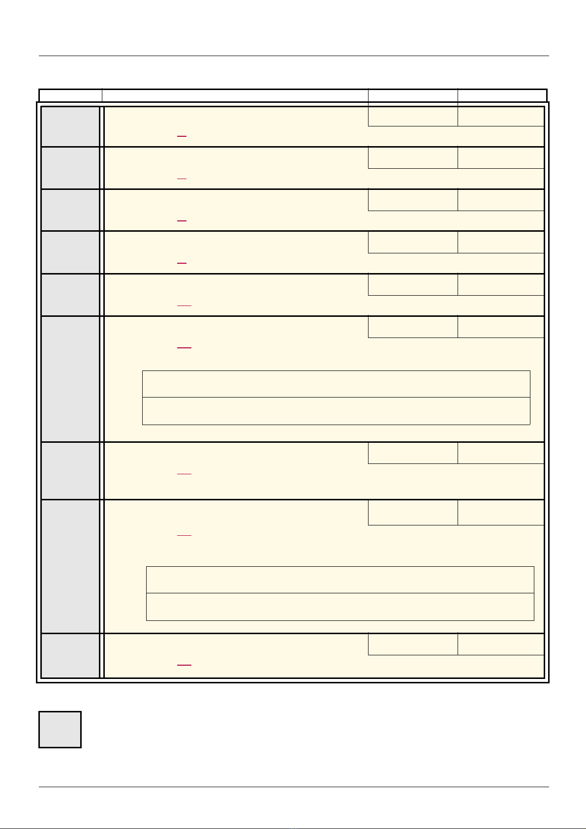
[1.3 SETTINGS] (SEt-)
CAUTION
Check that the motor will withstand this current without overheating.
Failure to follow this instruction can result in equipment damage.
CAUTION
Check that the motor will withstand this current without overheating.
Failure to follow this instruction can result in equipment damage.
Code Name/Description Adjustment range Factory setting
GPE
g
GIE
g
UFr
g
SLP
g
g
IdC
g
dCF
M [ENA prop.gain]
See page 81
M [ENA integral gain]
See page 81
M [IR compensation]
See page 74
M [Slip compensation]
See page 74
M [Ramp divider]
See page 141
M [DC inject. level 1]
See page 142
Level of DC injection braking current activated via logic input or selected as stop mode.
1 to 9999 250
0 to 9999 100
25 to 200% 100%
0 to 300% 100%
0 to 10 4
0.1 to 1.41 In (1) 0.64 In (1)
tdI
g
IdC2
g
tdC
g
(1)In corresponds to the rated drive current indicated in the Installation Manual or on the drive nameplate.
g
M [DC injection time 1]
See page 142
Maximum current injection time [DC inject. level 1] (IdC). After this time the injection current becomes
[DC
inject. level 2] (IdC2).
M [DC inject. level 2]
See page 142
Injection current activated by logic input or selected as stop mode, once period of time [DC injection time 1] (tdI)
has elapsed.
M [DC injection time 2]
See page 142
Maximum injection time [DC inject. level 2] (IdC2) for injection selected as stop mode only.
These parameters only appear if the corresponding function has been selected in another menu. When the parameters can
also be accessed and adjusted from within the confi guration menu for t he correspondin g function, thei r description is deta iled
in these menus, on the pages indicated, to aid progra mming.
0.1 to 30 s 0.5 s
0.1 In (2) to [DC inject.
level 1] (IdC)
0.1 to 30 s 0.5 s
0.5 In (1)
1755855 12/2009 59
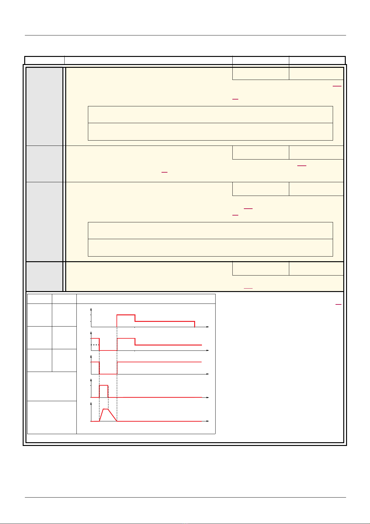
[1.3 SETTINGS] (SEt-)
CAUTION
Check that the motor will withstand this current without overheating.
Failure to follow this instruction can res u lt in equ ip m en t da m a ge .
CAUTION
Check that the motor will withstand this current without overheating.
Failure to follow this instruction can res u lt in equ ip m en t da m a ge .
AdC SdC2 Operation
YES
x
Ct
≠ 0
Ct
= 0
Run command
Speed
t
SdC1
SdC2
tdC1 tdC1 + tdC2
I
t
SdC1
I
t
SdC1
SdC2
tdC1
I
t
0
t
1
0
Code Name/Description Adjustment range Factory setting
SdC1
g
M [Auto DC inj. level 1]
Level of standstill DC injection current. This parameter can be accessed if [Auto DC injection] (AdC) pa ge 143
is not [No] (nO)
This parameter is forced to 0 if [Motor control type] (Ctt) page 71 = [S yn c. m o t.] (SYn).
0 to 1.2 In (1) 0.7 In (1)
tdCI
g
SdC2
g
tdC2
g
M [Auto DC inj. time 1]
Standstill injection time. This para meter can be accessed if [Auto DC injection] (AdC) page 143 is not [No] (nO)
If [Motor control type] (Ctt) page 71 = [FVC] (FUC) or [Sync. mot.] (SYn) this time corresponds to the zero speed
maintenance time.
M [Auto DC inj. level 2]
2nd level of standstill DC injection current.
This parameter can be accessed if [Auto DC injection] (AdC) page 143 is not [No] (nO)
This parameter is forced to 0 if [Motor control type] (Ctt) page 71 = [S yn c. m o t.] (SYn).
M [Auto DC inj. time 2]
2nd standstill injection time.
This parameter can be accessed if [Auto DC injection] (AdC) page 143 = [Yes] (YES)
0.1 to 30 s 0.5 s
0 to 1.2 In (1) 0.5 In (1)
0 to 30 s 0 s
Note: When [Moto r control type] (Ctt) page 71
= [FVC] (FUC):
[Auto DC inj. level 1] (SdC1), [Auto DC inj.
level
2] (SdC2) and [Auto DC inj. time 2]
(tdC2) are not accessible. Only [Auto DC inj.
time
1] (tdC1) can be accessed. This then
corresponds to a zero speed maintenance
time.
(1)In corresponds to the rated drive current indicated in the Installation Manual or on the drive nameplate.
60 1755855 12/2009

[1.3 SETTINGS] (SEt-)
CAUTION
On ATV71p075N4 to U40N4, drives, if the RFI filters are disconnected (operation on an IT system), the drive's
switching frequency must not exceed 4 kHz.
Failure to follow this instruction can result in equipment damage.
CAUTION
Check that the motor will withstand this current, particularly in the case of permanent magnet synchronous
motors, which are susceptible to demagnetization.
Failure to follow this instruction can result in equipment damage.
CAUTION
Check that the motor will withstand this current, particularly in the case of permanent magnet synchronous
motors, which are susceptible to demagnetization.
Failure to follow this instruction can result in equipment damage.
Code Name/Description Adjustment range Factory setting
SFr
M [Switching freq.]
Switching frequency setting.
Adjustment range: This can vary between 1 and 16 kHz, but the minimum and maximum values, as well as
the factory setting, can be limited in accordance with the type of drive (ATV71H or W), the rating (power and
voltage) and the configuration of the [Sinus filter] (OFI) and [Motor surge limit] (SUL) parameters, page
If the value is less than 2 kHz, [Current Limitation] (CLI) and [I Limit. 2 value] (CL2) page 61 are limited to
1.36 In.
Adjustment with drive running:
- If the initial value is less than 2 kHz, it is not possible to increase it above 1.9 kHz while running.
- If the initial value is greater than or equal to 2 kHz, a minimum of 2 kHz must be maintained while running.
Adjustment with the drive stopped: No restrictions.
Note: In the event of excessive temperature rise, the drive will automatically reduce the switching
frequency and reset it once the temperature returns to normal.
Note: If [Motor control type] (Ctt) page 71 = [FVC] (FUC), we do not recommend setting the swi tching
frequency to a value less than 2 kHz (in order to avoid speed instability).
.
According to rating According to rating
83.
CLI
CL2
g
M [Current Limitation]
Used to limit the motor current.
The adjustment range is limited to 1.36 In if [Switching freq.] (SFr) page 61 is less than 2 kHz.
Note: If the setting is less than 0.25 In, the drive may lo ck in [Output Phase Loss ] (OPF) fault mode if
this has been enabled (see page 224). If it is less t han the no-load motor current, the limi tation no longer
has any effect.
M [I Limit. 2 value]
See page 188
The adjustment range is limited to 1.36 In if [Switching freq.] (SFr) page 61 is less than 2 kHz.
Note: If the setting is less than 0.25 In, the drive may lo ck in [Output Phase Loss ] (OPF) fault mode if
this has been enabled (see page 224). If it is less t han the no-load motor current, the limi tation no longer
has any effect.
0 to 1.65 In (1) 1.5 In (1)
0 to 1.65 In (1) 1.5 In (1)
(1)In corresponds to the rated drive current indicated in the Installation Manual or on the drive nameplate.
These parameters only appear if the corresponding function has been selected in another menu. When the parameters can
g
1755855 12/2009 61
also be accessed and adjusted from within the confi guration menu for t he correspondin g function, thei r description is deta iled
in these menus, on the pages indicated, to aid progra mming.

[1.3 SETTINGS] (SEt-)
CAUTION
Check that the motor will withstand this current without overheating.
Failure to follow this instruction can result in equipment damage.
Code Name/Description Adjustment range Factory setting
FLU
FnC
FCt
FnO
M [Motor fluxing]
v [Not cont.] (FnC): Non-continuous mode
v [Continuous] (FCt): Continuous mode. This option is not possible if [Auto DC injection] (AdC) page 143 is
[Yes] (YES) or if [Type of stop] (Stt) page 141 is [Freewheel] (nSt).
v [No] (FnO): Function inactive This option is not possible if [Motor control type] (Ctt) page 71 = [SVCI] (CUC)
or [FVC] (FUC).
If [Motor control type] (Ctt) page 71 = [SVCI] (CUC), [FVC] (FUC) or [Sync. mot.] (SYn) the factory setting is
replaced by [Not cont.] (FnC).
In order to obtain rapid high torque on startup, magnetic flux needs to already have been established in the
motor.
•In [Continuous] (FCt) mode, the drive automatically builds up flux when it is powered up.
•In [Not cont.] (FnC) mode, fluxing occurs when the motor starts up.
The flux current is greater than nCr (configured rated motor current) when the flux is established and is then
adjusted to the motor magnetizing current...
[No] (FnO)
If [Motor control type] (Ctt) page 71 = [Sync. mot.] (SYn), the [Motor fluxing] (FLU) parameter causes the
alignment of the rotor and not the fluxing.
If [Brake assignment] (bLC) page 161 is not [No] (nO), the [Motor fluxing] (FLU) parameter has no effect.
tLS
JGF
g
JGt
g
(1)In corresponds to the rated drive current indicated in the Installation Manual or on the drive nameplate.
g
M [Low speed time out]
Maximum operating time at [Low speed] (LSP) (see page 44)
Following operation at LSP for a defined period, a mot or stop is requested automatically. The motor wi ll restart
if the reference is greater than LSP and if a run comman d is still present.
Caution: A value of 0 indicates an unlimited period of time.
Note: If [Low speed time out] (tLS) i s not 0, [Type of stop] (Stt) page 141 is forced to [Ramp stop] (rMP)
(only if a ramp stop can be configured).
M [Jog frequency]
See page 145
Reference in jog operation
M [Jog delay]
See page 145
Anti-repeat delay between 2 consecutive jog operations.
These parameters only appear if the corresponding function has been selected in another menu. When the parameters can
also be accessed and adjusted from within the confi guration menu for t he correspondin g function, thei r description is deta iled
in these menus, on the pages indicated, to aid progra mming.
0 to 999.9 s 0 s
0 to 10 Hz 10 Hz
0 to 2.0 s 0.5 s
62 1755855 12/2009
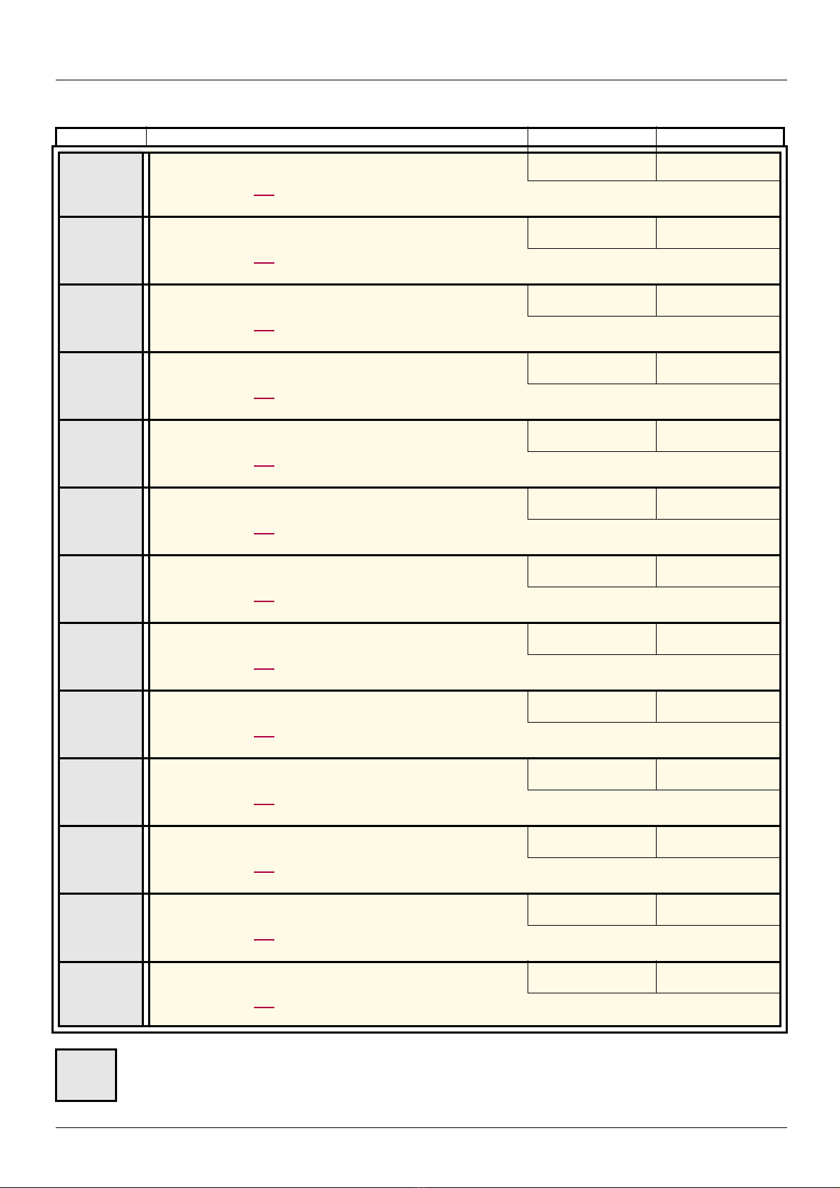
[1.3 SETTINGS] (SEt-)
Code Name/Description Adjustment range Factory setting
SP2
g
SP3
g
SP4
g
SP5
g
SP6
g
SP7
g
SP8
g
SP9
g
SP10
g
SP11
g
SP12
g
SP13
g
SP14
g
M [Preset speed 2]
See page 148
Preset speed 2
M [Preset speed 3]
See page 148
Preset speed 3
M [Preset speed 4]
See page 148
Preset speed 4
M [Preset speed 5]
See page 148
Preset speed 5
M [Preset speed 6]
See page 148
Preset speed 6
M [Preset speed 7]
See page 148
Preset speed 7
M [Preset speed 8]
See page 148
Preset speed 8
M [Preset speed 9]
See page 148
Preset speed 9
M [Preset speed 10]
See page 148
Preset speed 10
M [Preset speed 11]
See page 148
Preset speed 11
M [Preset speed 12]
See page 148
Preset speed 12
M [Preset speed 13]
See page 148
Preset speed 13
M [Preset speed 14]
See page 148
Preset speed 14
0 to 1600 Hz 10 Hz
0 to 1600 Hz 15 Hz
0 to 1600 Hz 20 Hz
0 to 1600 Hz 25 Hz
0 to 1600 Hz 30 Hz
0 to 1600 Hz 35 Hz
0 to 1600 Hz 40 Hz
0 to 1600 Hz 45 Hz
0 to 1600 Hz 50 Hz
0 to 1600 Hz 55 Hz
0 to 1600 Hz 60 Hz
0 to 1600 Hz 70 Hz
0 to 1600 Hz 80 Hz
These parameters only appear if the corresponding function has been selected in another menu. When the parameters can
g
1755855 12/2009 63
also be accessed and adjusted from within the confi guration menu for t he correspondin g function, thei r description is deta iled
in these menus, on the pages indicated, to aid progra mming.
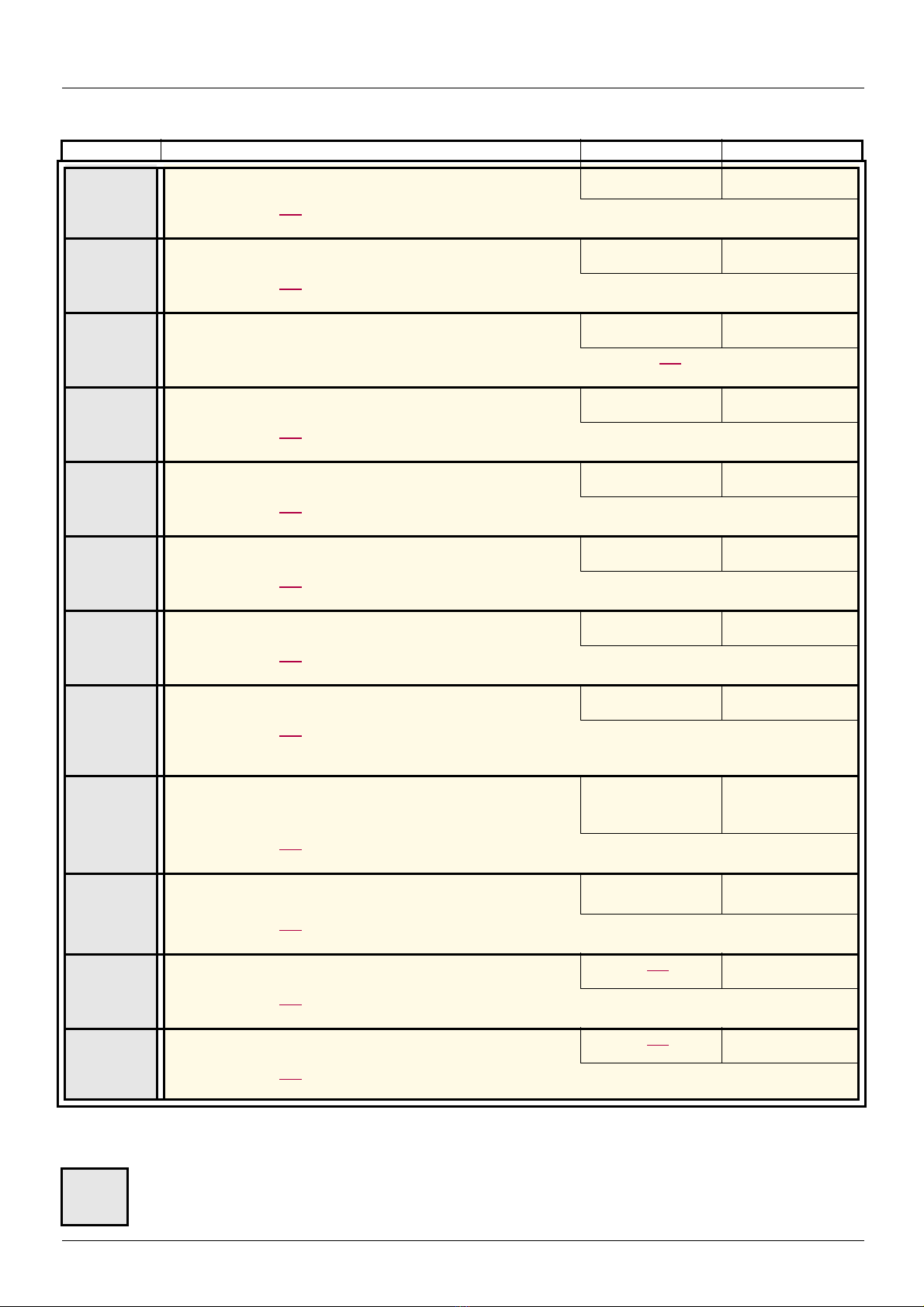
[1.3 SETTINGS] (SEt-)
Code Name/Description Adjustment range Factory setting
SP15
g
SP16
g
MFr
SrP
g
rPG
g
rIG
g
rdG
g
PrP
g
POL
g
POH
g
PAL
g
PAH
g
M [Preset speed 15]
See page 148
Preset speed 15
M [Preset speed 16]
See page 148
Preset speed 16
M [Multiplying coeff.]
Multiplying coefficient, can be accessed if [Multiplier ref.-] (MA2,MA3) page 136 has been assigned to the
graphic terminal
M [+/-Speed limitation]
See page 152
Limitation of +/- speed variation
M [PID prop. gain]
See page 177
Proportional gain
M [PID integral gain]
See page 178
Integral gain
M [PID derivative gain]
See page 178
Derivative gain
M [PID ramp]
See page 178
PID acceleration/deceleration ramp, defined to go from [Min PID reference] (PIP1) to [Max PID reference]
(PIP2) and vice versa.
M [Min PID output]
See page 178
Minimum value of regulator output in Hz
M [Max PID output]
See page 178
Maximum value of regulator output in Hz
M [Min fbk alarm]
See page 178
Minimum monitoring threshold for regulator feedback
M [Max fbk alarm]
See page 178
Maximum monitoring threshold for regulator feedback
0 to 1600 Hz 90 Hz
0 to 1600 Hz 100 Hz
0 to 100% 100%
0 to 50% 10%
0.01 to 100 1
0.01 to 100 1
0.00 to 100 0
0 to 99.9 s 0
- 500 to 500 or -1600
to 1600 according to
rating
0 to 500 or 1600
according to rating
See page 178 (1) 100
See page 178 (1) 1000
0 Hz
60 Hz
(1)If a graphic display terminal is not in use, values greater than 9999 will be displayed on the 4-digit display with a period mark after the
thousand digit, e.g., 15.65 for 15650.
These parameters only appear if the corresponding function has been selected in another menu. When the parameters can
g
64 1755855 12/2009
also be accessed and adjusted from within the confi guration menu for t he correspondin g function, thei r description is deta iled
in these menus, on the pages indicated, to aid progra mming.
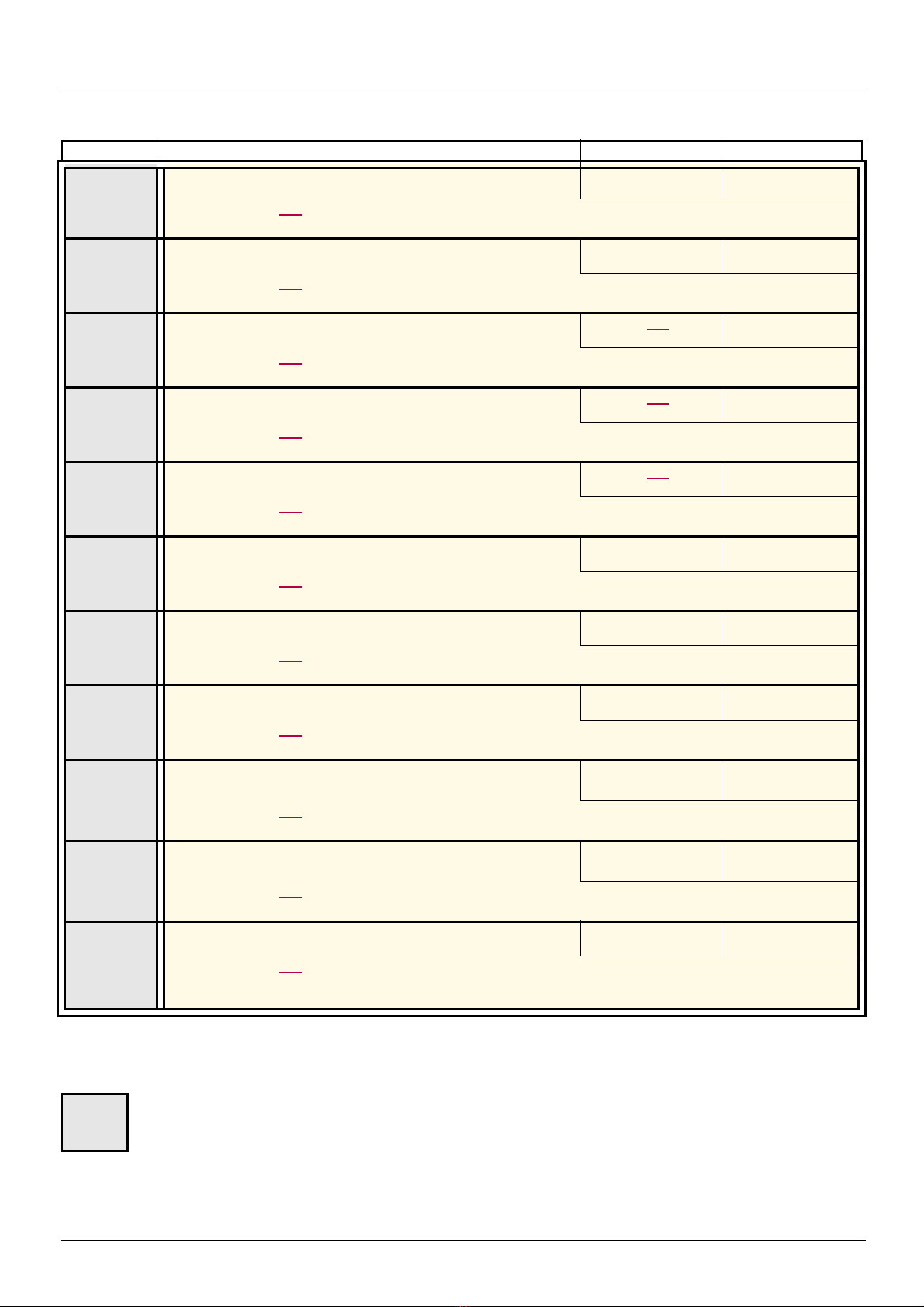
[1.3 SETTINGS] (SEt-)
Code Name/Description Adjustment range Factory setting
PEr
g
PSr
g
rP2
g
rP3
g
rP4
g
Ibr
g
Ird
g
brt
g
bIr
g
bEn
g
tbE
g
M [PID error Alarm]
See page 178
Regulator error monitoring threshold
M [Speed input %]
See page 179
Multiplying coefficient for predictive speed input.
M [Preset ref. PID 2]
See page 181
Preset PID reference
M [Preset ref. PID 3]
See page 181
Preset PID reference
M [Preset ref. PID 4]
See page 181
Preset PID reference
M [Brake release I FW]
See page 161
Brake release current threshold for lifting or forward movement
M [Brake release I Rev]
See page 161
Brake release current threshold for lowering or reverse movement
M [Brake Release time]
See page 162
Brake release time dela y
M [Brake release freq]
See page 162
Brake release frequency threshold
M [Brake engage freq]
See page 162
Brake engage frequency threshold
M [Brake engage delay]
See page 162
Time delay before request to engage brake. To delay the engaging of the brake, for horizontal movement only, if
you wish the brake to engage when the drive comes to a complete stop.
0 to 65535 (1) 100
1 to 100% 100%
See page 181 (1) 300
See page 181 (1) 600
See page 181 (1) 900
0 to 1.32 In (2) 0
0 to 1.32 In (2) 0
0 to 5.00 s 0 s
[Auto] (AUtO)
0 to 10 Hz
[Auto] (AUtO)
0 to 10 Hz
0 to 5.00 s 0 s
[Auto] (AUtO)
[Auto] (AUtO)
(1)If a graphic display terminal is not in use, values greater than 9999 will be displayed on the 4-digit display with a period mark after the
thousand digit, e.g., 15.65 for 15650.
(2)In corresponds to the rated drive current indicated in the Installation Manual or on the drive nameplate.
These parameters only appear if the corresponding function has been selected in another menu. When the parameters can
g
1755855 12/2009 65
also be accessed and adjusted from within the confi guration menu for t he correspondin g function, thei r description is deta iled
in these menus, on the pages indicated, to aid progra mming.

[1.3 SETTINGS] (SEt-)
Code Name/Description Adjustment range Factory setting
bEt
g
JdC
g
ttr
g
tLIM
g
tLIG
g
trH
g
M [Brake engage time]
See page 162
Brake engage time (brake response time)
M [Jump at reversal]
See page 163
M [Time to restart]
See page 163
Time between the end of a brake engage sequence and the start of a brake release sequence
M [Motoring torque lim]
See page 186
Torque limitation in generator mode, as a % or in 0.1% incremen ts of the rate d torq ue in accorda nce with the
[Torque increment] (IntP) parameter, page
M [Gen. torque lim]
See page 186
Torque limitation in generator mode, as a % or in 0.1% increments of the rated torque in accordance with the
[Torque increment] (IntP) parameter, page
M [Traverse freq. high]
See page 210
186.
186.
0 to 5.00 s 0 s
[Auto] (AUtO)
0 to 10 Hz
0.00 to 15.00 s 0.00 s
0 to 300% 100%
0 to 300% 100%
0 to 10 Hz 4 Hz
[Auto] (AUtO)
trL
g
qSH
g
qSL
g
Ctd
ttH
ttL
(1)In corresponds to the rated drive current indicated in the Installation Manual or on the drive nameplate.
M [Traverse freq. low]
See page 210
M [Quick step High]
See page 210
M [Quick step Low]
See page 210
M [Current threshold]
Current threshold for [I attained] (CtA) function assigned to a relay or a logic output (see page 103).
M [High torque thd.]
High current threshold for [High tq. att.] (ttHA) function assigned to a relay or a logic output (see page 103), as
a % of the rated motor torque.
M [Low torque thd.]
Low current threshold for [Low tq. att.] (ttLA) function assigned to a relay or a logic output (see page 103), as
a % of the rated motor torque.
0 to 10 Hz 4 Hz
0 to [Traverse freq.
high] (trH)
0 to [Traverse freq.
low] (trL)
0 to 1.5 In (1) In (1)
-300% to +300% 100%
-300% to +300% 50%
0 Hz
0 Hz
These parameters only appear if the corresponding function has been selected in another menu. When the parameters can
g
66 1755855 12/2009
also be accessed and adjusted from within the confi guration menu for t he correspondin g function, thei r description is deta iled
in these menus, on the pages indicated, to aid progra mming.
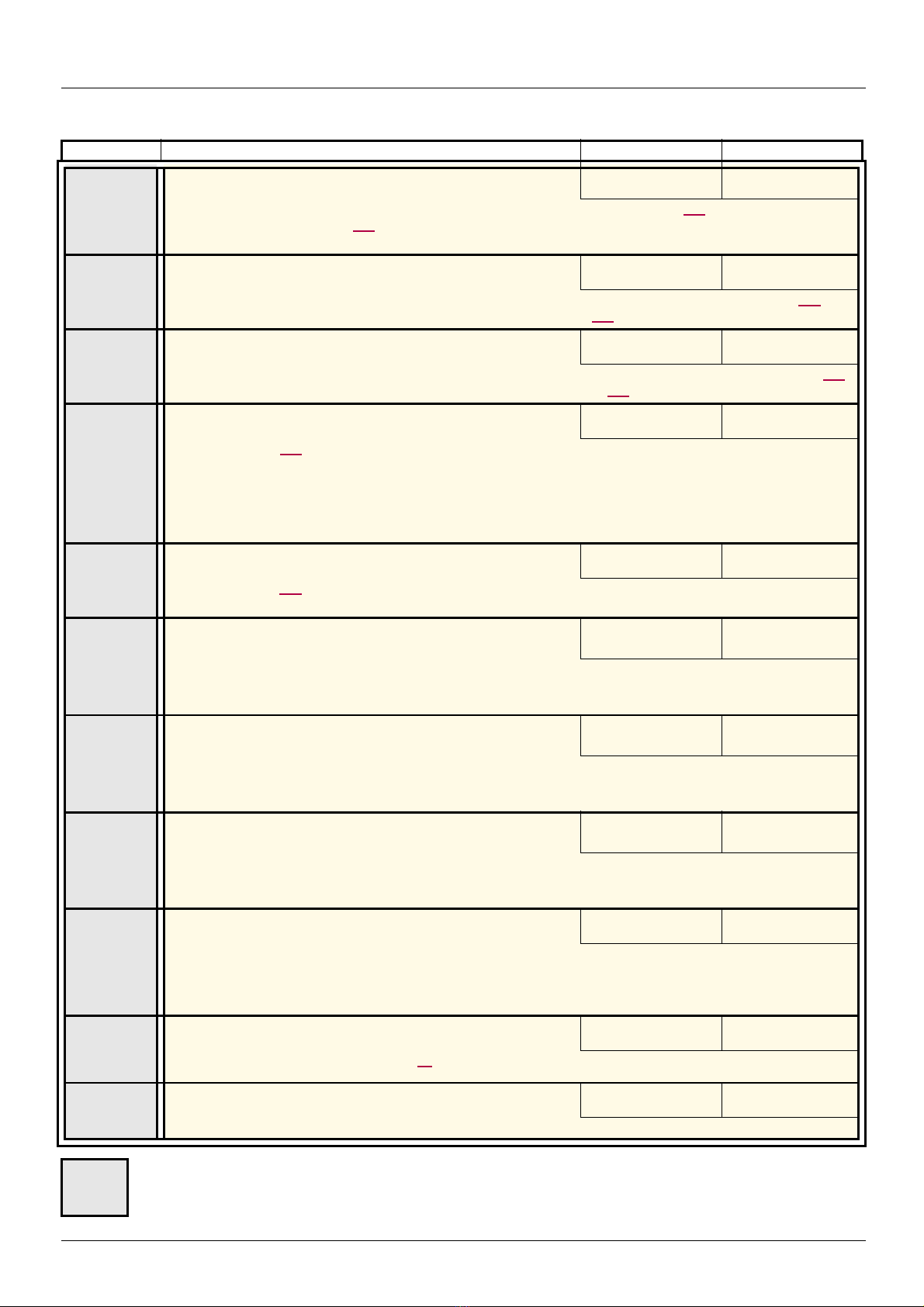
[1.3 SETTINGS] (SEt-)
Code Name/Description Adjustment range Factory setting
FqL
g
Ftd
F2d
FFt
g
ttd
g
JPF
JF2
JF3
JFH
M [Pulse warning thd.]
Speed threshold measured by the FREQUENCY METER] FqF-) function, page 235, assigned to a relay or a
logic output (see page 103).
M [Freq. threshold]
Frequency threshold for [Freq.Th.att.] (FtA) function assigned to a relay or a logic output (see page 103), or
used by the [PARAM. SET SWITCHING] (MLP-) function, page 199.
M [Freq. threshold 2]
Frequency threshold for [Freq. Th. 2 at tain.] (F2A) function assigned to a relay or a logic output (see page 103),
or used by the [PARAM. SET SWITCHING] (MLP-) function, page 199.
M [Freewheel stop Thd]
See page 141
This parameter supports switching from a ramp stop or a fast stop to a freewheel stop below a low speed
threshold.
It can be accessed if [Type of stop] (Stt) = [Fast stop] (FSt) or [Ramp stop] (rMP).
v 0.0: Does not switch to freewheel stop.
v 0,1 to 1600 Hz: Speed threshold below which the motor will switch to freewheel stop.
M [Motor therm. level]
See page 224
Trip threshold for motor thermal alarm (logic output or relay)
M [Skip Frequency]
Skip frequency. This parameter prevents prolonged operation within an adjustable range around the re gulated
frequency. This function can be used to prevent a critical speed, which would cause resonance, being reached.
Setting the function to 0 renders it inactive.
M [Skip Frequency 2]
2nd skip frequency. This parameter prevents prolonged operation within an adjustable range around the
regulated frequency. This function can be used to prevent a critical speed, which would cause resonance,
being
reached. Setting the function to 0 renders it inactive.
M [3rd Skip Frequency]
3rd skip frequency. This parameter prevents prolonged operation within an adjustable range around the
regulated frequency. This function can be used to prevent a critical speed, which would cause resonance,
being
reached. Setting the function to 0 renders it inactive.
M [Skip.Freq.Hysteresis]
Parameter visible if at least one skip frequency [Skip Frequency] (JPF), [Skip Frequency 2] (JF2) or [3rd Skip
Frequency] (JF3) is different from 0.
Skip frequency range: between (JPF – JFH) and (JPF + JFH), for example.
This adjustment is common to all 3 frequencies (JPF, JF2 and JF3).
0 Hz to 30.00 kHz 0 Hz
0.0 to 1600 Hz [High speed] (HSP)
0.0 to 1600 Hz [High speed] (HSP)
0.0 to 1600 Hz 0.0 Hz
0 to 118% 100%
0 to 500 or 1,600 Hz
according to rating
0 to 500 or 1,600 Hz
according to rating
0 to 500 or 1,600 Hz
according to rating
0.1 to 10 Hz 1 Hz
0 Hz
0 Hz
0 Hz
LbC
g
trt
T
g
1755855 12/2009 67
M [Load correction]
Rated correction in Hz. See page 85
M [Torque ratio]
Coefficient applied to [Torque reference] (tr 1).
These parameters only appear if the corresponding function has been selected in another menu. When the parameters can
also be accessed and adjusted from within the confi guration menu for t he correspondin g function, thei r description is deta iled
in these menus, on the pages indicated, to aid progra mming.
0 to 1000 Hz 0
0 to 1000% 100%
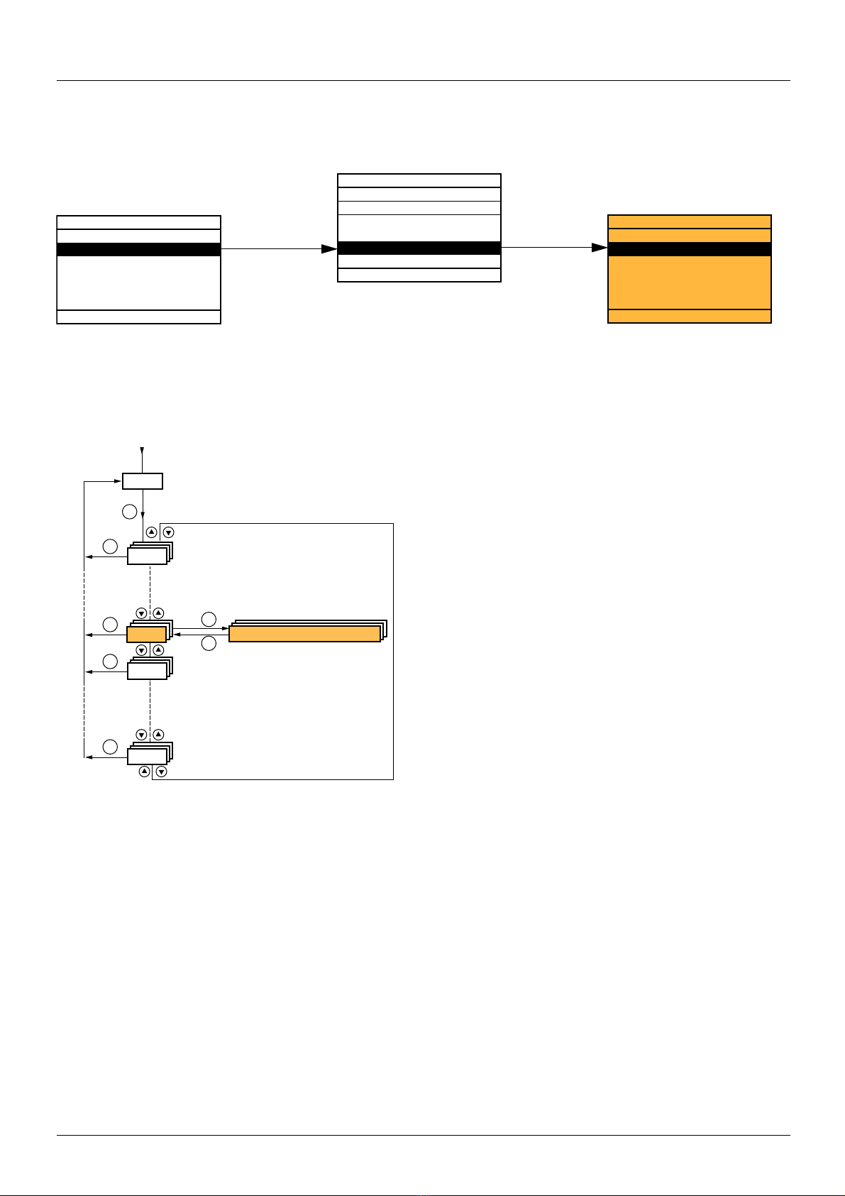
[1.4 MOTOR CONTROL] (drC-)
RDY Term +0.00Hz 0A
MAIN MENU
1 DRIVE MENU
2 ACCESS LEVEL
3 OPEN / SAVE AS
4 PASSWORD
5 LANGUAGE
Code Quick
ENT
RDY Term +0.00Hz 0A
1 DRIVE MENU
1.1 SIMPLY START
1.2 MONITORING
1.3 SETTINGS
1.4 MOTOR CONTROL
1.5 INPUTS / OUTPUTS CFG
Code << >> Quick
ENT
RUN Term +50.00Hz 80A
1.4 MOTOR CONTROL
Standard mot. freq
Rated motor power
Rated motor volt.
Rated mot. current
Rated motor freq.
Code << >> Quick
XXX
SIM-
I-O-
ESC
ESC
ESC
ESC
ENT
ENT
ESC
LAC-
drC-
Displays the state of the drive
MOTOR CONTROL
Power-up
With graphic display terminal:
With integrated display terminal:
68 1755855 12/2009

[1.4 MOTOR CONTROL] (drC-)
100 - slip as a %
100
50 - slip in Hz
50
60 - slip in Hz
60
The parameters in the [1.4 MOTOR CONTROL] (drC-) menu can only be modified when the drive is stopped and no run command is
present, with the following exceptions:
• [Auto tuning] (tUn) page 70, which may cause the motor to start up.
• Parameters containing the sign Tin the code column, which can be modified with the drive running or stopped.
Code Name/Description Adjustment range Factory setting
bFr
nPr
UnS
nCr
FrS
M [Standard mot. freq]
50
60
v [50Hz IEC] (50): IEC
v [60Hz NEMA] (60) : NEMA
This parameter modifies the presets of the following para meters: [High speed] (HSP) page 44, [Freq. t hreshold]
(Ftd) page 67, [Rated motor volt.] (UnS), [Rated motor freq.] (FrS) and [Max frequency] (tFr).
M [Rated motor power]
The parameter cannot be accessed if [Motor control type] (Ctt) page 71 = [Sync. mot.] (SYn).
Rated motor power given on the nameplate, in kW if [Standard mot. freq] (bFr) = [50Hz IEC] (50), in HP if
[Standard mot. freq] (bFr) = [60Hz NEMA] (60).
M [Rated motor volt.]
The parameter cannot be accessed if [Motor control type] (Ctt) page 71 = [Sync. mot.] (SYn).
Rated motor voltage given on the nameplate.
ATV71pppM3: 100 to 240 V - ATV71pppN4: 200 to 480 V - ATV71pppY: 400 to 690 V.
M [Rated mot. current]
The parameter cannot be accessed if [Motor control type] (Ctt) page 71 = [Sync. mot.] (SYn).
Rated motor current given on the nameplate.
M [Rated motor freq.]
The parameter cannot be accessed if [Motor control type] (Ctt) page 71 = [Sync. mot.] (SYn).
Rated motor frequency given on the nameplate.
The factory setting is 50 Hz, or preset to 60 Hz if [Standard mot. freq] (bFr) is set to 60 Hz.
The maximum value is limited to 500 Hz if [Motor control type] (Ctt) (page 71) is not V/F, or for ATV71pppY
drives, or for drives rated higher than ATV71HD37.
Values between 500 Hz and 1600 Hz are only possible in V/F control and for powers limited to 37 kW (50 HP).
In this case configure [Motor control type] (Ctt) before [Rated motor freq.] (FrS).
[50Hz IEC] (50)
According to drive
rating
According to drive
rating
0.25 to 1.5 In (1) According to drive
10 to 1600 Hz 50 Hz
According to drive
rating
According to drive
rating and [Standard
mot. freq] (bFr)
rating and [Standard
mot. freq] (bFr)
InSP
nSP
(1)In corresponds to the rated drive current indicated in the Installation Manual and on the drive nameplate.
1755855 12/2009 69
M [rpm increment]
Increment of parameter [Rated motor speed] (nSP).
1
10
v [x1 rpm] (1): Increment of 1 rpm, to be used if [Rated motor speed] (nSP) does not exceed 65535 rpm.
v [x10 rpm] (10) : Increment of 10 rpm, to be used if [Rated motor speed] (nSP) exceeds 65535 rpm.
Note 1: Changing [rpm increment] (InSP) will restore [Rated motor speed] (nSP) to its factory setting.
Note 2: For ATV71pppY range, [rpm increment] (InSP) is fixed to 1.
M [Rated motor speed]
The parameter cannot be accessed if [Motor control type] (Ctt) page 71 = [Sync. mot.] (SYn).
Rated motor speed given on the nameplate. Adjustable between 0 and 65535 rpm if [rpm increment] (InSP) =
[x1 rpm] (1) or between 0.00 and 96.00 krpm if [rpm increment] (InSP) = [x10 rpm] (10).
0 to 9999 rpm then 10.00 to 65.53 or 96.00 krpm on the integrated display terminal.
If, rather than the rated speed, the nameplate indicates the synchronous speed and the slip in Hz or as a %,
calculate the rated speed as follows:
• Nominal speed = Synchronous speed x
or
• Nominal speed = Synchronous speed x (50 Hz motors)
or
• Nominal speed = Synchronous speed x (60 Hz motors)
0 to 96000 rpm According to drive
[x1 rpm] (1)
rating

[1.4 MOTOR CONTROL] (drC-)
Code Name/Description Factory setting
tFr
tUn
dOnE
nO
YES
M [Max frequency]
The factory setting is 60 Hz, or preset to 72 Hz if [Standard mot. freq] (bFr) is set to 60 Hz.
The maximum value is limited by the following conditions:
• It must not exceed 10 times the value of [Rated motor freq.] (FrS)
• It must not exceed 500 Hz if [Motor control type] (Ctt) (page 71) is not V/ F or for ATV71pppY drives, or for
drives rated higher than ATV71HD37.
Values between 500 Hz and 1600 Hz are only possible in V/F control and for powers limited to 37 kW
(50
HP). In this case configure [Motor control type] (Ctt) before [Max frequency] (tFr).
M [Auto tuning]
10 to 1600 Hz
[No] (nO)
v [No] (nO): Auto-tuning not performed.
v [Yes] (YES): Auto-tuning is performed as soon as possible, then the parameter automatically changes to [Done]
(dOnE).
v [Done] (dOnE) : Use of the values given the last time auto-tuning was performed.
Caution:
• It is essential that all the motor parameters are correctly configured before starting auto-tuning.
- Asynchronous motor: [Rated motor volt.](UnS), [Rated motor freq.] (FrS), [Rated mot. current] (nCr),
[Rated motor speed] (nSP), [Rated motor power] (nPr)
- Synchronous motor: [Nominal I sync.] (nCrS), [Nom motor spdsync] (nSPS), [Pole pairs] (PPnS), [Syn.
EMF constant] (PHS), [Autotune L d-axis] (LdS), [Autotune L q-axis] (LqS)
If one or more of these parameters is modified after auto-tuning has been performed, [Auto tuning] (tUn) will
return to [No] (nO) and the procedure must be repeated.
• Auto-tuning is only performed if no stop command has been activated. If a "freewheel stop" or "fast stop"
function has been assigned to a logic input, this input must be set to 1 (active at 0).
• Auto-tuning takes priority over any run or prefluxing commands, which will be taken into account after the
auto-tuning sequence.
• If auto-tuning fails, the drive displays [No] (nO) and, depending on the configuration of [Autotune faul t mgt]
(tnL) page
• Auto-tuning may last for 1 to 2 seconds. Do not interrupt the process. Wait for the display to change to
"[Done] (dOnE)" or "[No] (nO)".
238, may switch to [Auto-tuning] (tnF) fault mode.
AUt
tUS
PEnd
PrOG
FAIL
dOnE
PHr
nO
YES
tAb
CUS
AbC
ACb
Note: During auto-tuning the motor operates at rated current.
M [Automatic autotune]
[No] (nO)
v [No] (nO): Function inactive
v [Yes] (YES): Auto-tuning is performed on every power-up.
Caution: Same comments as for [Auto tuning] (tUn) above.
If [Profile] (CHCF) = [8 serie] (SE8), then [Automatic autotune] (AUt) is fixed to [No] (nO).
M [Auto tuning state]
For information only, cannot be modified.
[Not done] (tAb)
v [Not done] (tAb): The default stator resistance value is used to control the motor.
v [Pending] (PEnd): Auto-tuning has been requested but not yet performed.
v [In Progress] (PrOG): Auto-tuning in progress
v [Failed] (FAIL): Auto-tuning has failed.
v [Done] (dOnE) : The stator resistance measured by the auto-tuning function is used to control the motor.
v [Customized] (CUS): Auto-tuning has been performed, but at least one parameter set by this auto-tuning
operation has subsequently been modified. The [Auto tuning] (tUn) parameter then returns to [No] (nO). The
following auto-tuning parameters are affected:
[Cust. stator R syn] (rSAS) page 74, [Cust stator resist.] (rSA), [Idw] (IdA), [LFw] (LFA) and [T2w] (trA) page 75.
M [Output Ph rotation]
[ABC] (AbC)
v [ABC] (AbC): Forward
v [ACB] (ACb): Reverse
This parameter can be used to reverse the direction of rotation of the motor without reversing the wiring.
Do not modify the [Output Ph rotation] (PHr) parameter when [Motor control type] (Ctt)
page 71 = [FVC] (FUC). The direction of rotation must be modified, if required, before or during the
procedure to check the encoder page 78 when [Motor control type] (Ctt) is not [FVC] (FUC).
70 1755855 12/2009
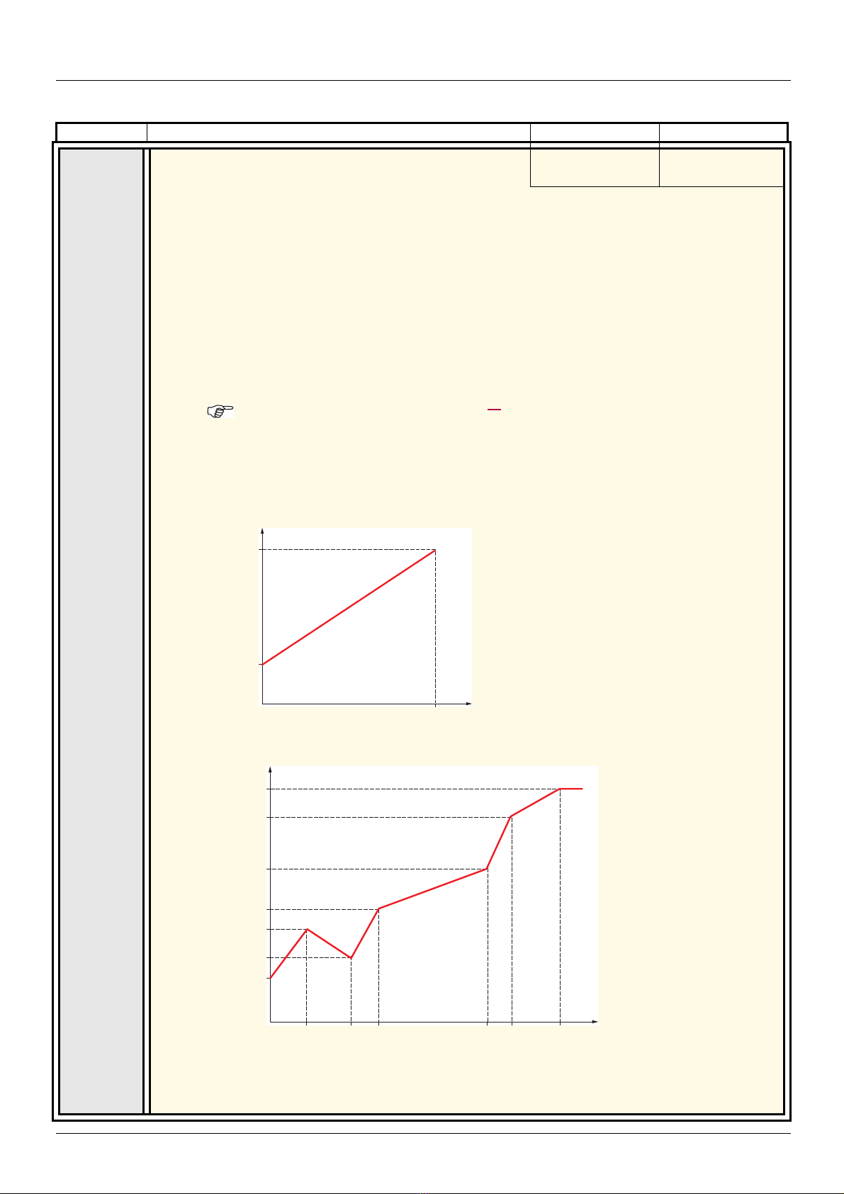
[1.4 MOTOR CONTROL] (drC-)
Voltage
Frequency
FrS
UnS
U0
The profile is defined by
the values of parameters
UnS, FrS and U0.
Voltage
Frequency
FrS
UnS
U5
U4
U3
U1
U2
U0
F1 F2
F3
F4 F5
FrS > F5 > F4 > F3 > F2 > F1
The profile is defined
by the values of
parameters UnS, FrS,
U0 to U5 and F0 to F5.
Code Name/Description Adjustment range Factory setting
Ctt
UUC
CUC
FUC
UF2
M [Motor control type]
[SVC V] (UUC)
v [SVC V] (UUC): Open-loop voltage flux vector control with automatic slip compen sation according to the load.
This type of control is recommended when replacing an ATV58. It supports operation wit h a number of motors
connected in parallel on the same drive (if the motors are identical).
v [SVC I] (CUC): Open-loop current flux vector control. This type of control is re commended when replacing an
ATV58F used in an open-loop configuration. It does not support operation with a numbe r of motors connected
in parallel on the same drive.
v [FVC] (FUC) : Closed-loop current flux vector control for motors with incremental encoder type sensor; this
option can only be selected if an incremental encoder card has been inserted. This function is not possible,
however, when using an encoder that generates signal "A" only.
This type of control is recommended when replacing an ATV58F used in a closed-loop configuration. It provi des
better performance in terms of speed and torque accuracy and enables torque to be obtained at zero speed. It
does not support operation with a number of motors connected in parallel on the same drive.
It is essential that the encoder check page 78 is performed successfully before selecting [FVC]
(FUC).
v [V/F 2pts] (UF2): Simple V/F profile without slip compensation. It supports operation with:
- Special motors (wound rotor, tapered rotor, etc.)
- A number of motors in parallel on the same drive
- High-speed motors
- Motors with a low power rating in comparison to that of the drive
UF5
SYn
1755855 12/2009 71
v [V/F 5pts] (UF5): 5-segment V/F profile: As V/F 2 pts profile but also supports the avoidance of resonance
(saturation).
v [Sync. mot.] (SYn): For synchronous permanent magnet motors with sinusoidal electromotive force (EMF)
only. This selection is prohibited with ATV71
This selection makes the asynchronous motor parameters inaccessible, and the synchron ous motor
parameters accessible.
ppppY ( 500 to 690 V).

[1.4 MOTOR CONTROL] (drC-)
Code Name/Description Adjustment range Factory setting
U0
U1
F1
U2
F2
U3
F3
U4
F4
U5
F5
M [U0]
M [U1]
M [F1]
M [U2]
M [F2]
M [U3]
M [F3]
M [U4]
M [F4]
M [U5]
M [F5]
0 to 600 or 1000 V
according to rating
V/F profile setting. The parameter can be accessed if [Motor control type] (Ctt) = [V/F 2pts] (UF2) or [V/F 5pts]
(UF5)
0 to 600 or 1000 V
according to rating
V/F profile setting. The parameter can be accessed if [Motor control type] (Ctt) = [V/F 5pts] (UF5)
0 to 1600 Hz 0
V/F profile setting. The parameter can be accessed if [Motor control type] (Ctt) = [V/F 5pts] (UF5)
0 to 600 or 1000 V
according to rating
V/F profile setting. The parameter can be accessed if [Motor control type] (Ctt) = [V/F 5pts] (UF5)
0 to 1600 Hz 0
V/F profile setting. The parameter can be accessed if [Motor control type] (Ctt) = [V/F 5pts] (UF5)
0 to 600 or 1000 V
according to rating
V/F profile setting. The parameter can be accessed if [Motor control type] (Ctt) = [V/F 5pts] (UF5)
0 to 1600 Hz 0
V/F profile setting. The parameter can be accessed if [Motor control type] (Ctt) = [V/F 5pts] (UF5)
0 to 600 or 1000 V
according to rating
V/F profile setting. The parameter can be accessed if [Motor control type] (Ctt) = [V/F 5pts] (UF5)
0 to 1600 Hz 0
V/F profile setting. The parameter can be accessed if [Motor control type] (Ctt) = [V/F 5pts] (UF5)
0 to 600 or 1000 V
according to rating
V/F profile setting. The parameter can be accessed if [Motor control type] (Ctt) = [V/F 5pts] (UF5)
0 to 1600 Hz 0
V/F profile setting. The parameter can be accessed if [Motor control type] (Ctt) = [V/F 5pts] (UF5)
0
0
0
0
0
0
72 1755855 12/2009

[1.4 MOTOR CONTROL] (drC-)
Motor voltage
Frequency
Rated motor freq.
Max. voltage UCP
Freq. Const Power FCP
Rated motor volt. UnS
Code Name/Description Adjustment range Factory setting
UC2
UCP
FCP
nO
YES
M [Vector Control 2pt]
The parameter can be accessed if [Motor control type] (Ctt) is not [Sync. mot.] (SYn).
v [No] (nO): Function inactive
v [Yes] (YES): Function active.
Used in applications in which the motor rated speed and frequency nee d to be exceeded in order to optimize
operation at constant power, or when the maximum voltage of the motor needs to be limited to a value below
the line voltage.
The voltage/frequency profile must then be adapted in accordance with the motor's capabilities to operate at
maximum voltage UCP and maximum frequency FCP.
M [V. constant power]
The parameter can be accessed if [Vector Control 2pt] (UC2) = [Yes] (YES)
M [Freq. Const Power]
The parameter can be accessed if [Vector Control 2pt] (UC2) = [Yes] (YES)
According to drive
rating
According to drive
rating and [Rated
motor freq.] (FrS)
[No] (nO)
According to drive
rating and [Standard
mot. freq] (bFr)
= [Standard mot. freq]
(bFr)
1755855 12/2009 73

[1.4 MOTOR CONTROL] (drC-)
Synchronous motor parameters:
These parameters can be accessed if [Motor control type] (Ctt) page 71 = [Sync. mot.] (SYn). In this case, the asynchronous motor
parameters cannot be accessed.
Code Name/Description Adjustment range Factory setting
nCrS
nSPS
PPnS
PHS
LdS
LqS
rSAS
M [Nominal I sync.]
Rated synchronous motor current given on the nameplate.
M [Nom motor spdsync]
Rated motor speed given on the nameplate.
On the integrated display unit: 0 to 9999 rpm then 10.00 to 60.00 krpm.
M [Pole pairs]
Number of pairs of poles on the synchronous motor.
M [Syn. EMF constant]
Synchronous motor EMF constant, in mV per rpm (peak voltage per phase).
On the integrated display unit: 0 to 9999 then 10.00 to 65.53 (10000 to 65536).
M [Autotune L d-axis]
Axis "d" stator inductance in mH (per phase).
On motors with smooth poles [Autotune L d-axis] (LdS) = [Autotune L q-axis] (LqS) = Stator inductance L.
M [Autotune L q-axis]
Axis "q" stator inductance in mH (per phase).
On motors with smooth poles [Autotune L d-axis] (LdS) = [Autotune L q-axis] (LqS) = Stator inductance L.
M [Cust. stator R syn]
Cold state stator resistance (per winding) The factory setting is replaced by the result of the auto-tuning
operation, if it has been performed.
The value can be entered by the user, if he knows it.
Value in milliohms (mΩ) up to 75 kW (100 HP), in hundredths of milliohms (mΩ/100) above 75 kW (100 HP).
On the integrated display unit: 0 to 9999 then 10.00 to 65.53 (10000 to 65536).
0.25 to 1.5 In (2) According to drive
rating
0 to 60000 rpm According to drive
rating
1 to 50 According to drive
rating
0 to 65535 According to drive
rating
0 to 655.3 According to drive
rating
0 to 655.3 According to drive
rating
According to drive
rating
According to drive
rating
Code Name/Description Adjustment range Factory setting
UFr
T
SLP
T
(1)The parameter can also be accessed in the [1.3 SETTINGS] (SEt-) menu.
(2)In corresponds to the rated drive current indicated in the Installation Manual and on the drive nameplate.
T
74 1755855 12/2009
M [IR compensation]
The parameter can be accessed if [Motor control type] (Ctt) is not [V/F 2pts] (UF2) and [V/F 5pts] (UF5).
Used to optimize the torque at very low speed (increase [IR compensation] (UFr) if the torque is insufficient).
Check that the [IR compensation] (UFr) value is not to o high when t he motor is warm (risk of i nstability).
M [Slip compensation]
The parameter can be accessed if [Motor control type] (Ctt) is not [V/F 2pts] (UF2), [V/F 5pts] (UF5) and
[Sync.
mot.] (SYn).
Adjusts the slip compensation around the value set by the rated motor speed.
The speeds given on motor nameplates are not necessarily exact.
• If slip setting < actual slip: The motor is not rotating at the correct speed in steady state, but at a speed lower
than the reference.
• If slip setting > actual slip: The motor is overcompensated and the speed is unstable.
Parameter that can be modified during operation or when stopped.
(1)
(1) 0 to 300% 100%
25 to 200% 100%

[1.4 MOTOR CONTROL] (drC-)
Motor parameters that can be accessed in [Expert] mode.
These include:
• Parameters calculated by the drive during auto-tuning, in read-only mode. For example, R1r, calculated cold stator resistance.
• The possibility of replacing some of these calculated parameters by other values, if necessary. For example, R1w, measured cold
stator resistance.
When a parameter Xyw is modified by the user, the drive uses it in place of the calculated parameter Xyr.
Asynchronous motor
If an auto-tuning operation is performed or if one of the motor parameters on which auto-tuning depends is modified ([Rated motor volt.]
(UnS), [Rated motor freq.] (FrS), [Rated mot. current] (nCr), [Rated motor speed] (nSP), [ Rated motor power] (nPr)), parameters Xyw return
to their factory settings.
Code Name/Description
rSM
IdM
LFM
trM
nSL
PPn
rSA
M [Stator R measured]
Cold stator resistance, calculated by the drive, in read-only mode. Value in milliohms (mΩ) up to 75 kW
(100
HP), in hundredths of milliohms (mΩ/100) above 75 kW (100 HP).
M [Idr]
Magnetizing current in A, calculated by the drive, in read-only mode.
M [Lfr]
Leakage inductance in mH, calculated by the drive, in read-only mode.
M [T2r]
Rotor time constant in mS, calculated by the drive, in read-only mode.
M [Nominal motor slip]
Rated slip in Hz, calculated by the drive, in read-only mode.
To modify the rated slip, modify the [Rated motor speed] (nSP) (pa ge 69).
M [Pr]
Number of pairs of poles, calculated by the drive, in read-only mode.
M [Cust stator resist.]
Cold state stator resistance (per winding), modifiable value. In milliohms (mΩ) up to 75 kW (100 HP), in
hundredths of milliohms (m
10.00 to 65.53 (10000 to 65536).
Ω/100) above 75 kW (100 HP). On the integrated display unit: 0 to 9999 then
IdA
LFA
trA
1755855 12/2009 75
M [Idw]
Magnetizing current in A, modifiable value.
M [Lfw]
Leakage inductance in mH, modifiable value.
M [T2w]
Rotor time constant in mS, modifiable value.

[1.4 MOTOR CONTROL] (drC-)
Synchronous motor
Code Name/Description
rSMS
FrSS
M [R1rS]
Cold state stator resistance (per winding), in read-only mode. This is the drive factory setting or the result
of the auto-tuning operation, if it has been performed.
Value in milliohms (mΩ) up to 75 kW (100 HP), in hundredths of milliohms (mΩ/100) above 75 kW (100 HP).
On the integrated display unit: 0 to 9999 then 10.00 to 65.53 (10000 to 65536).
M [Nominal freq sync.]
Motor frequency at rated speed in Hz, calculated by the drive (rated motor frequency), in read-only mode.
76 1755855 12/2009

[1.4 MOTOR CONTROL] (drC-)
Selecting the encoder
Follow the recommendations in the catalog and the Installat ion Manual.
Code Name/Description Adjustment range Factory setting
EnS
AAbb
PGI
(1)The encoder parameters can only be accessed if the encoder card has been inserted, and the available selections will depend on the
type of encoder card used. The encoder configuration can also be accessed in the [1.5- INPUTS / OUTPUTS CFG] (I/O) menu.
M [Encoder type]
The parameter can be accessed if an incremental encoder card has been inserted (1).
To be configured in accordance with the type of card and encoder used.
v [AABB] (AAbb): For signals A, A-, B, B-.
Ab
A
v [AB] (Ab): For signals A, B.
v [A] (A): For signal A. Value cannot be accessed if [Encoder usage] (EnU) page 79 = [Spd fdk reg.] (rEG).
M [Number of pulses]
Number of pulses per encoder revolution.
The parameter can be accessed if an incremental encoder card has been inserted (1).
100 to 5000 1024
[AABB] (AAbb)
1755855 12/2009 77

[1.4 MOTOR CONTROL] (drC-)
Encoder check procedure
This procedure applies to all types of encoder.
1. Set [Motor control type] (Ctt) to a value other than [FVC] (FUC) even if it is the required config uration. For example, use [SVC V] (UUC)
for an asynchronous motor and [Sync. mot.] (SYn) for a synchronous motor.
2. Configure the motor parameters in accordance with the specifications on the rating plate.
• Asynchronous motor (see page 69): [Rated motor powe r] (nPr), [Rated motor volt.] (UnS), [Rated mot. current] (nCr), [Rated motor
freq.] (FrS), [Rated motor speed] (nSP).
• Synchronous motor (see "Synchronous motor parameters" on page 74): [Nominal I sync.] (nCrS), [Nom motor spdsync] (nSPS), [Pole
pairs] (PPnS), [Syn. EMF constant] (PHS), [Autotune L d-axis] (LdS), [Autotune L q-axis] (L qS), [Cus t. stator R syn] (rSAS). [Current
limitation] (CLI) must not exceed the maximum motor current, otherwise demagnetization may occur .
3. Set [Encoder usage] (EnU) = [No] (nO).
4. Perform auto-tuning.
5. In the case of an incremental encoder, set [Encoder type] (EnS) and [Number of pulses] (PGI) page 77 according to the encoder used.
6. Set [Encoder check] (EnC) = [Yes] (YES)
7. Check that the rotation of the motor is safe.
8. Set the motor rotating at stabilized speed ≈ 15% of the rated speed for at least 3 seconds, and use the [1.2-MONITORING] (SUP-) menu
to monitor its behavior.
9. If it trips on an [Encoder fault] (EnF), [Encoder check] (EnC) returns to [No] (nO).
- Check the parameter settings (see points 1 to 4 above).
- Check that the mechanical and electrical operation of the encoder, its power supply and connections are all OK.
- Reverse the direction of rotation of the motor ([Output Ph rotation] (PHr) parameter page 70) or the encoder signals.
10. Repeat the operations from step 5 onwards until [Enco der check] (EnC) changes to [Done] (dOnE).
11. If necessary, change [Motor control type] (Ctt) to [FVC] (FUC).
78 1755855 12/2009

[1.4 MOTOR CONTROL] (drC-)
Code Name/Description Adjustment range Factory setting
EnC
YES
dOnE
EnU
SEC
rEG
PGr
(1)The encoder parameters can only be accessed if the encoder card has been inserted, and the available selections will depend on the
type of encoder card used. The encoder configuration can also be accessed in the [1.5- INPUTS / OUTPUTS CFG] (I/O) menu.
M [Encoder check]
Encoder feedback check. See procedure on previous page.
The parameter can be accessed if an encoder card has been inserted (1).
nO
v [Not done] (nO) Check not performed.
v [Yes] (YES): Activates monitoring of the encoder.
v [Done] (dOnE) : Check performed successfully.
The check procedure checks:
- The direction of rotation of the encoder/motor
- The presence of signals (wiring continuity)
- The number of pulses/revolution
If a fault is detected, the drive locks in [Encoder fault] (EnF) fault mode.
M [Encoder usage]
The parameter can be accessed if an encoder card has been inserted (1).
nO
v [No] (nO): Function inactive
v [Fdbk monit.] (SEC): The encoder provides speed feedback for monitoring only.
v [Spd fdk reg.] (rEG): The encoder provides speed feedback for regulation and monitoring. This
configuration is automatic if the drive is configured for closed-loop operation ([Motor co ntrol type] (Ctt) = [FVC]
(FUC). If [Motor control type] (Ctt) = [SVC V] (UUC) the encoder operates in speed feedback mode and enables
static correction of the speed to be performed. Th is configuration is not accessible f or other [Motor control type]
(Ctt) values.
v [Speed ref.] (PGr) : The encoder provides a reference. Can only be selected with an incremental encoder
card.
[Not done] (nO)
[No] (nO)
1755855 12/2009 79

[1.4 MOTOR CONTROL] (drC-)
Beam pumps
[ENA SYSTEM]
ENA SYSTEM is a control profile designed for rotating machines with unbalanced load.
It is used primarily for oil pumps. The operating principle applied:
- Allows operation without a braking resistor
- Reduces mechanical stress on the rod
- Reduces line current fluctuations
- Reduces energy consumption by improving the electric power/current ratio
[ENA prop.gain]
This setting is used to achieve a compromise between the reduced energy consumption (and/or line current fluctuations) and the
mechanical stress to which the rod is subject.
Energy is saved by reducing current fluctuations and increasing the current while retaining the same average speed.
[ENA integral gain]
This setting is used to smooth the DC bus voltage.
Start up the machine with a low integral and proportional gain (proportional 25% and integral 10%) in order to avoid an overvoltage trip in
the absence of a braking resistor. See if these settings are suitable.
Recommended adjustments to be made during operation:
• To eliminate the braking resistor and, therefore, the increase in the DC bus voltage:
Display the machine speed on the graphic display terminal.
Reduce the integral gain value until the machine speed dr ops. When this point is reached, increase the i ntegral gain until the machine
speed stabilizes.
Use the graphic display terminal or an oscilloscope to check that the DC bus voltage is stable.
• To save energy:
Reducing the proportional gain (gradually) may increase energy savings by reduci ng the maximum value of the line current, but it will
increase speed variations and, therefore, mechanical stress.
The aim is to identify settings that will enable energy to be saved and minimize mechanical stress.
When reducing the proportional gain, it may be necessary to readjust the integral gain in order to avoid an overvoltage trip.
Note: Once the adjustments are complete, check that t he pump starts up correctly. I f the ENA inte gral gain sett ing is to o low, this may le ad
to insufficient torque on startup.
[Reduction ratio]
This setting corresponds to the motor speed ahead of gearbox/speed after gearbox ratio. This parameter is used to display the average
speed in Hz and the machine speed in customer units (e.g., i n strokes pe r minut e) on the graphi c displa y terminal . In order t o be displayed
on the graphic display terminal, these values must be selected in the [1.2 MONITORING] (SUP-) menu.
Adjustment recommendations for prevention of tripping on an [Overspeed] (SOF) fault
ENA SYSTEM authorizes overspeed, which can trigger an [Overspeed] (SOF) fault. To avoid this occurring, it is advisable to increase the
value of the following parameters slightly:
• [Max frequency] (tFr) page 70
• [Overspd. pulse thd.] (FqA) page 235, if the "frequency meter" function is configured
80 1755855 12/2009

[1.4 MOTOR CONTROL] (drC-)
Beam pumps
Code Name/Description Adjustment range Factory setting
EnA
YES
GPE
T
GIE
T
rAP
T
(1)The parameter can also be accessed in the [1.3 SETTINGS] (SEt-)menu.
T
M [ENA system]
The parameter can be accessed if [Motor control type] (Ctt) = [SVC V] (UUC), see page 71.
nO
v [No] (nO) : Function inactive
v [Yes] (YES) : Function active.
M [ENA prop.gain]
The parameter can be accessed if [ENA system] (EnA) = [Yes] (YES)
M [ENA integral gain]
The parameter can be accessed if [ENA system] (EnA) = [Yes] (YES)
M [Reduction ratio]
The parameter can be accessed if [ENA system] (EnA) = [Yes] (YES)
Parameter that can be modified during operation or when stopped.
[No] (nO)
(1) 1 to 9999 250
(1) 0 to 9999 100
(1) 10.0 to 999.9 10
1755855 12/2009 81
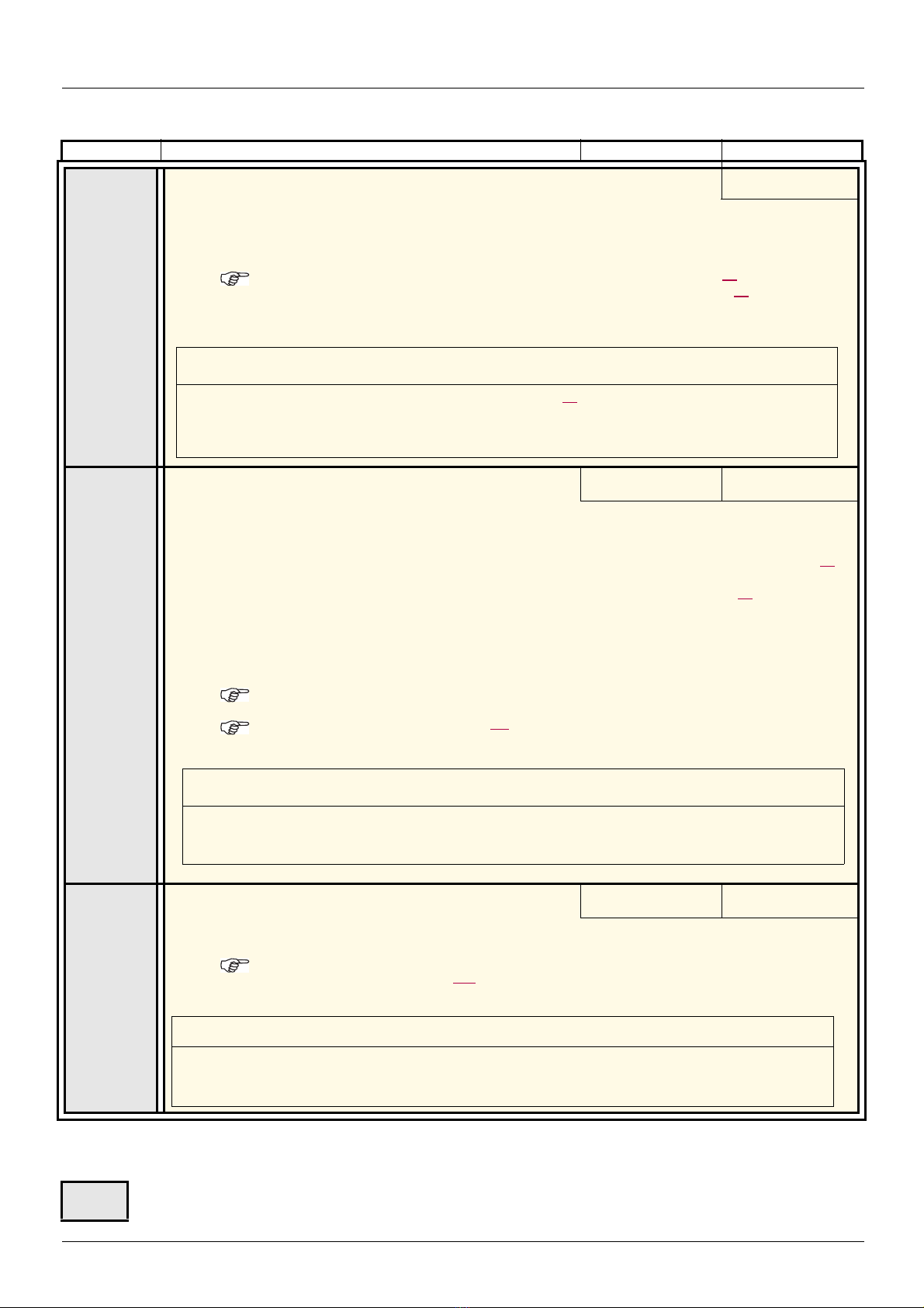
[1.4 MOTOR CONTROL] (drC-)
CAUTION
If [Sinus filter] (OFI) = [Yes] (YES), [Motor control type] (Ctt) page 71 must be [V/F 2pts] (UF2), [V/F 5pts] (UF5),
(or [SVC V] (UUC) only up to 45 kW for ATV71
pppM3X and 75 kW for ATV71pppN4), and [Max frequency]
(tFr) must not exceed 100 Hz.
Failure to follow this instruction can result in equipment damage.
CAUTION
On ATV71p075N4 to U40N4, drives, if the RFI filters are disconnected (operati on on an IT system), the drive's
switching frequency must not exceed 4 kHz.
Failure to follow this instruction ca n result in equipment damage.
CAUTION
Check that the motor will withstand this current, particularly in the case of permanent magnet synchronous
motors, which are susceptible to demagnetization.
Failure to follow this instruction can result in equipment damage.
Code Name/Description Adjustment range Factory setting
OFI
SFr
T
nO
YES
M [Sinus filter]
[No] (nO)
v [No] (nO): No sinus filter
v [Yes] (YES): Use of a sinus filter, to limit overvoltages on the motor and reduce the ground fault leakage
current.
[Sinus filter] (OFI) is forced to [No] (nO) on ATV71p037M3 and ATV71p075N4, and on all ATV71ppppY.
Note: The sett ings for [Current Limitation] (CL I) and [I Limit. 2 value] (CL2) page 61 must be made once
[Sinus filter] (OFI) has been se t to [Yes] (YES) a nd [Motor control type] (C tt) page 71 has been set to [V/
F 2pts] (UF2) or [V/F 5pts] (UF5). This is due to the fact that for certain ratings, this configuration will
result in a reduced factory setting (1.36 In) for current limitations.
M [Switching freq.]
Switching frequency setting.
Adjustment range: This can vary between 1 and 16 kHz, but the minimum and maximum values, as well as
the factory setting, can be limited in accordance with the type of drive (ATV71H or W), the rating (power and
voltage) and the configuration of the [Sinus filter] (OFI) and [Motor surge limit] (SUL) parameters, page
If the value is less than 2 kHz, [Current Limitation] (CLI) and [I Limit. 2 value] (CL2) page 61 are limited to
1.36 In.
Adjustment with drive running:
- If the initial value is less than 2 kHz, it is not possible to increase it above 1.9 kHz while running.
- If the initial value is greater than or equal to 2 kHz, a minimum of 2 kHz must be maintained while running.
Adjustment with the drive stopped: No restrictions.
Note: In the event of excessive temperature rise, the drive will automatically reduce the switching
frequency and reset it once the temperature returns to normal.
Note: If [Motor control type] (Ctt) page 71 = [FVC] (FUC), we do not recommend setting the swi tching
frequency to a value less than 2 kHz (in order to avoid speed instability).
(1) According to rating According to rating
83.
CLI
T
(1)The parameter can also be accessed in the [1.3 SETTINGS] (SEt-)menu.
(2)In corresponds to the rated drive current indicated in the Installation Manual and on the drive nameplate.
T
M [Current Limitation]
Used to limit the motor current.
The adjustment range is limited to 1.36 In if [Switching freq.] (SFr) is less than 2 kHz.
Note: If the setting is less than 0.25 In, the drive may lo ck in [Output Phase Loss ] (OPF) fault mode if
this has been enabled (see page 224). If it is less t han the no-load motor current, the limi tation no longer
has any effect.
Parameter that can be modified during operation or when stopped.
(1) 0 to 1.65 In (2) 1.5 In (2)
82 1755855 12/2009

[1.4 MOTOR CONTROL] (drC-)
Code Name/Description Adjustment range Factory setting
nrd
SUL
SOP
nO
YES
nO
YES
M [Noise reduction]
According to rating
v [No] (nO): Fixed frequency. Factory setting at and above ATV71HD55M3X, ATV71HD90N4 and
ATV71HC11Y.
v [Yes] (YES): Frequency with random modulation. Factory setting up to ATV71HD45M3X, ATV71 HD75N4 and
ATV71HD90Y.
Random frequency modulation prevents any resonance, which may occur at a fixed frequency.
M [Motor surge limit.]
This function limits motor overvoltages and is useful in the followi ng applications:
-NEMA motors
- Japanese motors
- Spindle motors
- Rewound motors
[No] (nO)
v [No] (nO) : Function inactive
v [Yes] (YES) : Function active
This parameter is forced to [No] (nO) if [Sinus filter] (OFI) previous page = [Yes] (YES).
This parameter can remain = [No] (nO) for 230/40 0 V motors used at 2 30 V, or if the length of cable between
the drive and the motor does not exceed:
- 4 m with unshielded cables
- 10 m with shielded cables
M [Volt surge limit. opt]
Optimization parameter for transient overvoltages at the motor terminals. Can be accessed if [Motor surge
limit.] (SUL) = [Yes] (YES).
Set to 6, 8, or 10 μs, according to the following table.
10 μs
The value of the "SOP" parameter corresponds to the attenuation time of the cable used. It is defined to prevent the superimposition of
voltage wave reflections resulting from long cable lengths. It limits overvoltages to twice the DC bus rated voltage.
The tables on the following page give examples of correspo ndence be tween th e "SOP" parameter and the l ength o f the cabl e between the
drive and the motor. For longer cable lengths, a sinus filter or a dV/dt prot ection filter must be used.
• For motors in parallel, the sum of all the cable lengths must be taken into consideration. Compare the length given in the table row
corresponding to the power for one motor with that corresponding to th e total power, and select the shorter length. Example: Two
7.5
kW (10 HP) motors - take the lengths on the 15 kW (20 HP) table row, which are shorter than those on the 7.5 kW (10 HP) row,
and divide by the number of motors to obtain the length per motor (with unshielded "GORSE" cable and SOP = 6, the result is
40/2 = 20 m maximum for each 7.5 kW (10 HP) motor).
In special cases (for example, different types of cable, different motor powers in parallel, different cable lengths in parallel, etc.), we
recommend using an oscilloscope to check the overvoltage values obtained at the motor terminals.
To retain the overall drive performance, do not increase the SOP value unnecessarily.
1755855 12/2009 83

[1.4 MOTOR CONTROL] (drC-)
Tables giving the correspondence between the SOP parameter and the cable length,
for 400 V line supply
Altivar 71 Motor Cable cross-section Maximum cable length in meters
Reference Power Unshielded "GORSE" cable
kW HP in mm
ATV71H075N4 0.75 1 1.5 14 109.36 yd 76.55 yd 49.21 yd 114.83 yd 92.96 yd 71.08 yd
ATV71HU15N4 1.5 2 1.5 14 109.36 yd 76.55 yd 49.21 yd 114.83 yd 92.96 yd 71.08 yd
ATV71HU22N4 2.2 3 1.5 14 120.30 yd 71.08 yd 49.21 yd 114.83 yd 92.96 yd 71.08 yd
ATV71HU30N4 3 - 1.5 14 120.30 yd 71.08 yd 49.21 yd 114.83 yd 92.96 yd 71.08 yd
ATV71HU40N4 4 5 1.5 14 120.30 yd 71.08 yd 49.21 yd 114.83 yd 92.96 yd 71.08 yd
ATV71HU55N4 5.5 7.5 2.5 14 131.23 yd 71.08 yd 49.21 yd 114.83 yd 92.96 yd 71.08 yd
ATV71HU75N4 7.5 10 2.5 14 131.23 yd 71.08 yd 49.21 yd 114.83 yd 92.96 yd 71.08 yd
ATV71HD11N4 11 15 6 10 125.77 yd 65.62 yd 49.21 yd 109.36 yd 82.02 yd 60.15 yd
ATV71HD15N4 15 20 10 8 114.83 yd 65.62 yd 43.74 yd 109.36 yd 76.55 yd 54.68 yd
ATV71HD18N4 18.5 25 10 8 125.77 yd 65.62 yd 38.28 yd 164.04 yd 82.02 yd 54.68 yd
ATV71HD22N4 22 30 16 6 164.04 yd 65.62 yd 43.74 yd 164.04 yd 76.55 yd 54.68 yd
ATV71HD30N4 30 40 25 4 164.04 yd 60.15 yd 38.28 yd 164.04 yd 76.55 yd 54.68 yd
ATV71HD37N4 37 50 35 5 218.72 yd 71.08 yd 54.68 yd 164.04 yd 76.55 yd 54.68 yd
ATV71HD45N4 45 60 50 0 218.72 yd 60.15 yd 32.81 yd 164.04 yd 65.62 yd 43.74 yd
ATV71HD55N4 55 75 70 2/0 218.72 yd 54.68 yd 27.34 yd 164.04 yd 60.15 yd 32.81 yd
ATV71HD75N4 75 100 95 4/0 218.72 yd 49.21 yd 27.34 yd 164.04 yd 60.15 yd 32.81 yd
2
AWG SOP = 10 SOP = 8 SOP = 6 SOP = 10 SOP = 8 SOP = 6
Type H07 RN-F 4Gxx
Shielded "GORSE" cable
Type GVCSTV-LS/LH
Altivar 71 Motor Cable cross-section Maximum cable length in meters
Reference Power Shielded "BELDEN" cable
kW HP in mm
ATV71H075N4 0.75 1 1.5 14 54.68 yd 43.74 yd 32.81 yd
ATV71HU15N4 1.5 2 1.5 14 54.68 yd 43.74 yd 32.81 yd
ATV71HU22N4 2.2 3 1.5 14 54.68 yd 43.74 yd 32.81 yd
ATV71HU30N4 3 - 1.5 14 54.68 yd 43.74 yd 32.81 yd
ATV71HU40N4 4 5 1.5 14 54.68 yd 43.74 yd 32.81 yd
ATV71HU55N4 5.5 7.5 2.5 14 54.68 yd 43.74 yd 32.81 yd
ATV71HU75N4 7.5 10 2.5 14 54.68 yd 43.74 yd 32.81 yd
ATV71HD11N4 11 15 6 10 54.68 yd 43.74 yd 32.81 yd
ATV71HD15N4 15 20 10 8 54.68 yd 43.74 yd 32.81 yd
ATV71HD18N4 18.5 25 10 8 54.68 yd 43.74 yd 32.81 yd
ATV71HD22N4 22 30 16 6 82.02 yd 43.74 yd 27.34 yd
ATV71HD30N4 30 40 25 4 82.02 yd 43.74 yd 27.34 yd
ATV71HD37N4 37 50 35 5 82.02 yd 43.74 yd 27.34 yd
ATV71HD45N4 45 60 50 0 82.02 yd 43.74 yd 27.34 yd
ATV71HD55N4 55 75 70 2/0 82.02 yd 32.81 yd 16.40 yd
ATV71HD75N4 75 100 95 4/0 82.02 yd 32.81 yd 16.40 yd
For 230/400 V motors used at 230 V, the [Motor surge limit.] (SUL) parameter can remain = [No] (nO).
2
AWG SOP = 10 SOP = 8 SOP = 6 SOP = 10 SOP = 8 SOP = 6
Type 2950x
Shielded "PROTOFLEX" cable
Type EMV 2YSLCY-J
84 1755855 12/2009

[1.4 MOTOR CONTROL] (drC-)
LbC
LbC
Torque
Nominal torque
Nominal torque
Frequency
0
Code Name/Description Adjustment range Factory setting
Ubr
T
bbA
nO
YES
M [Braking level]
DC bus voltage threshold above which the braking transistor cuts in to limit this voltage.
ATV71ppppM3p: factory setting 395 V.
ATV71ppppN4: factory setting 785 V.
ATV71ppppS6x: factory setting 980 V.
ATV71ppppY: factory setting 1127 V or 1080 V according to rating.
The adjustment range depends on the voltage rating of the drive and the [Mains voltage] (UrES) parameter,
page
228.
M [Braking balance]
v [No] (nO) : Function inactive
v [Yes] (YES) : Function active, to be used on drives connected in parallel via their DC bus. Used to balance
the braking power between the drives. The [Braking level] (Ubr) parameter must be set to the same value on
the various drives.
The value[Yes] (YES) is possible only if [Dec ramp adapt.] (brA) = [No] (nO) (see page 140)
According to drive
voltage rating
[No] (nO)
LbA
LbC
T
nO
YES
M [Load sharing]
When 2 motors are connected mechanically and therefor e at the same speed, and each is controlled by a drive,
this function can be used to improve torque distri bution between the two mo tors. To do this, it varies the speed
based on the torque.
v [No] (nO) : Function inactive
v [Yes] (YES) : Function active
The parameter can only be accessed if [Motor control type] (Ctt) page 71 is not [V/F 2pts] (UF2) or [V/F 5pts]
(UF5).
M [Load correction]
Rated correction in Hz.
The parameter can be accessed if [Load sharing] (LbA) = [Yes] (YES)
[No] (nO)
(1) 0 to 1000 Hz 0
(1)The parameter can also be accessed in the [1.3 SETTINGS] (SEt-)menu.
1755855 12/2009 85
T
Parameter that can be modified during operation or when stopped.

[1.4 MOTOR CONTROL] (drC-)
+
-
Reference
Speed
Ramp
Speed loop
Balancing
K
Filter
Torque reference
LBC
LBC1
LBC2
LBC3
LBF
K1
Speed
LBC1 LBC2
1
K2
Torque
LBC3
LBC3
Rated
torque x (1 + LBC3)
LBC
LBC
Load sharing, parameters that can be accessed at expert level
Principle
The load sharing factor K is determined by the torque and speed, with two factors K1 and K2 (K = K1 x K2).
86 1755855 12/2009

[1.4 MOTOR CONTROL] (drC-)
Code Name/Description Adjustment range Factory setting
LbC1
T
LbC2
T
LbC3
T
LbF
T
T
M [Correction min spd]
The parameter can be accessed if [Load sharing] (LbA) = [Yes] (YES)
Minimum speed for load correction in Hz. Below this threshold, no corrections are made. Used to prevent
correction at very low speed if this would hamper rotation of the motor.
M [Correction max spd]
The parameter can be accessed if [Load sharing] (LbA) = [Yes] (YES)
Speed threshold in Hz above which maximum load correction is applied.
M [Torque offset]
The parameter can be accessed if [Load sharing] (LbA) = [Yes] (YES)
Minimum torque for load correction as a % of th e rated t orque. Below thi s threshold, no c orrections are made.
Used to avoid torque instabilities when the torque direction is not constant.
M [Sharing filter]
The parameter can be accessed if [Load sharing] (LbA) = [Yes] (YES)
Time constant (filter) for correction in ms. Used in the even t of flexible mechanical coupling in order to avoid
instabilities.
Parameter that can be modified during operation or when stopped.
0 to 999.9 Hz 0
[Correction min spd]
(LbC1) + 0.1
at 1000 Hz
0 to 300% 0%
100 ms to 20 s 100 ms
0,1
1755855 12/2009 87

[1.5 INPUTS / OUTPUTS CFG] (I-O-)
RDY Term +0.00Hz 0A
MAIN MENU
1 DRIVE MENU
2 ACCESS LEVEL
3 OPEN / SAVE AS
4 PASSWORD
5 LANGUAGE
Code Quick
ENT
RDY Term +0.00Hz 0A
1 DRIVE MENU
1.1 SIMPLY START
1.2 MONITORING
1.3 SETTINGS
1.4 MOTOR CONTROL
1.5 INPUTS / OUTPUTS CFG
Code << >> Quick
ENT
RUN Term +50.00Hz 80A
1.5 INPUTS / OUTPUTS CFG
2/3 wire control
2 wire type
Reverse assign.
LI1 CONFIGURATION
LIx CONFIGURATION
Code << >> Quick
XXX
CtL-
SIM-
I-O-
ESC
ESC
ESC
ESC
ENT
ENT
ESC
LAC-
Displays the state of the drive
INPUTS / OUTPUTS CFG
Power-up
With graphic display terminal:
With integrated display terminal:
88 1755855 12/2009

[1.5 INPUTS / OUTPUTS CFG] (I-O-)
+24 LI1 LIx
ATV 71
+24 LI1 LI2 LIx
ATV 71
WARNING
UNINTENDED EQUIPMENT OPERATION
To change the assignment of [2/3 wire control] (tCC) press and hold down the “ENT” key for 2 s.
It causes the following functions to return to fac to ry sett i ng: [2 wire type] (tCt) and [R everse as sign.]
(rrS) below, and all functions which assign logic inputs and analog inputs.
The macro configuration selected will also be reset it if has been customized (loss of cus tom settings).
It is advisable to configure this parameter before configuring the [1.6 COMMAND] (CtL-) and [1.7
APPLICATION FUNCT.] (FUn-) menus.
Check that this change is compatible with the wiring diagram used.
Failure to follow these instructions can result in death or serious injury.
The parameters in the [1.5 INPUTS / OUTPUTS CFG] (I-O-) menu can only be modified when th e drive is stopped and no run comman d is
present.
Code Name/Description Adjustment range Factory setting
tCC
M [2/3 wire control]
2C
3C
v [2 wire] (2C)
v [3 wire] (3C)
2-wire control: This is the input state (0 or 1) or edge (0 to 1 or 1 to 0), which controls running or stopping.
Example of "source" wiring:
3-wire control (pulse commands): A "forward" or "reverse" pulse is sufficient to command starting, a "stop"
pulse is sufficient to command stopping.
Example of "source" wiring:
[2 wire] (2C)
LI1: forward
LIx: reverse
LI1: stop
LI2: forward
LIx: reverse
1755855 12/2009 89
tCt
LEL
trn
PFO
rrS
LI1
C101
Cd00
M [2 wire type]
v [Level] (LEL): State 0 or 1 is taken into account for run (1) or stop (0).
v [Transition] (trn): A change of state (transition or edge) is nec essary to initiate operation, in order to prevent
accidental restarts after a break in the power supply.
v [Fwd priority] (PFO): State 0 or 1 is taken into account for run or stop, but th e "forward" input alway s takes
priority over the "reverse" input.
M [Reverse assign.]
nO
v [No] (nO): Not assigned
v [LI1] (LI1) to [LI6] (LI6)
-
-
v [LI7] (LI7) to [LI10] (LI10): If VW3A3201 logic I/O card has been inserted
v [LI11] (LI11) to [LI14] (LI14): If VW3A3202 extended I/O card has been inserted
v [C101] (C101) to [C115] (C115): With integrated Modbus in [I/O profile] (IO)
-
-
-
v [C201] (C201) to [C215] (C215): With integrated CANopen in [I/O profile] (IO)
v [C301] (C301) to [C315] (C315): With a communication card in [I/O profile] (IO)
v [C401] (C401) to [C415] (C415): With a Controller Inside card in [I/O profile] (IO)
v [CD00] (Cd00) to [CD13] (Cd13): In [I/O profile] (IO) can be switched with possible logic inputs
-
v [CD14] (Cd14) to [CD15] (Cd15): In [I/O profile] (IO) can be switched without logic inputs
Assignment of the reverse direction command.
[Transition] (trn)
[LI2] (LI2)
[1.5 INPUTS / OUTPUTS CFG] (I-O-)
WARNING
UNINTENDED EQUIPMENT OPERATION
Check that the delay set does not pose a risk or lead to undesired operation.
The relative order in which these inputs a re taken into account may be modifi ed according to the delay
values of the various logic inputs, and thus lead to unintended operation.
Failure to follow these instructions can result in death or serious injury.
Code Name/Description Adjustment range Factory setting
L1-
L--
L1A
L1d
b [LI1 CONFIGURATION]
M [LI1 assignment]
Read-only parameter, cannot be configured.
It displays all the functions that are assigned to input LI1 in order to check for multiple assignments.
M [LI1 On Delay]
This parameter is used to take account of the change of the logic input to state 1 with a delay that can be
adjusted between 0 and 200 milliseconds, in order to fil ter out possibl e interfer ence. The change to s tate 0
is taken into account without delay.
b [LIx CONFIGURATION]
All the logic inputs available on th e d rive are p rocesse d a s i n t he examp le fo r LI 1 a bove, u p t o L I6, LI1 0 o r
LI14, depending on whether or not option cards have been inserted.
0 to 200 ms 0
90 1755855 12/2009
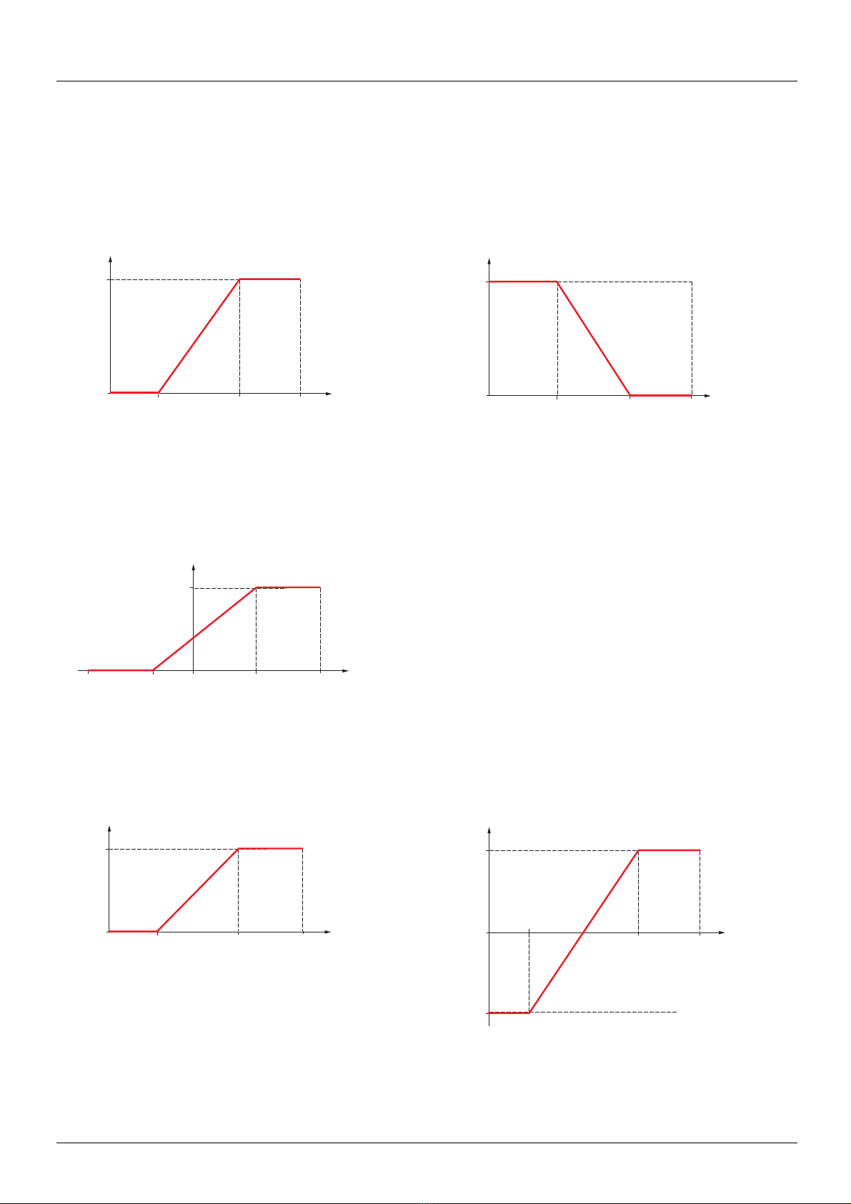
[1.5 INPUTS / OUTPUTS CFG] (I-O-)
Reference
100%
0%
[Min value]
(CrLx or
ULx or PIL)
[Max value]
(CrHx or
UHx or PFr)
20 mA or
10 V or
30.00 kHz
Reference
100%
0%
[Min value]
(CrLx or
ULx or PIL)
[Max value]
(CrHx or
UHx or PFr)
Current or
voltage or
frequency
input
Current or
voltage or
frequency
input
20 mA or
10 V or
30.00 kHz
Reference
100%
0%
[RP min
value]
(PIL)
[RP max value]
(PFr)
30.00
kHz
Frequency
input
-30,00
kHz
Reference
100%
0%
[Min value] [Max value]
Range 0
V 100%
Reference
100%
0%
[Min value]
[Max value]
Current
or
voltage
input
Current
or
voltage
input
- 100%
Range - 100%
V + 100%
20 mA
or 10 V
20 mA
or 10 V
Configuration of analog inputs and Pulse input
The minimum and maximum input values (in volts, mA, etc.) are converted to % in order to adapt the references to the application.
Minimum and maximum input values:
The minimum value corresponds to a reference of 0% and the maximum value to a reference of 100%. The minimum value may be greater
than the maximum value:
For +/- bidirectional inputs, the min. and max. are relative to the absolute value, for example, +/- 2 to 8 V.
Negative min. value of Pulse input:
Range (output values): For analog inputs only
This parameter is used to configure the reference range to [0% V100%] or [-100% V +100%] in order to obtain a bidirectional output from
a unidirectional input.
1755855 12/2009 91
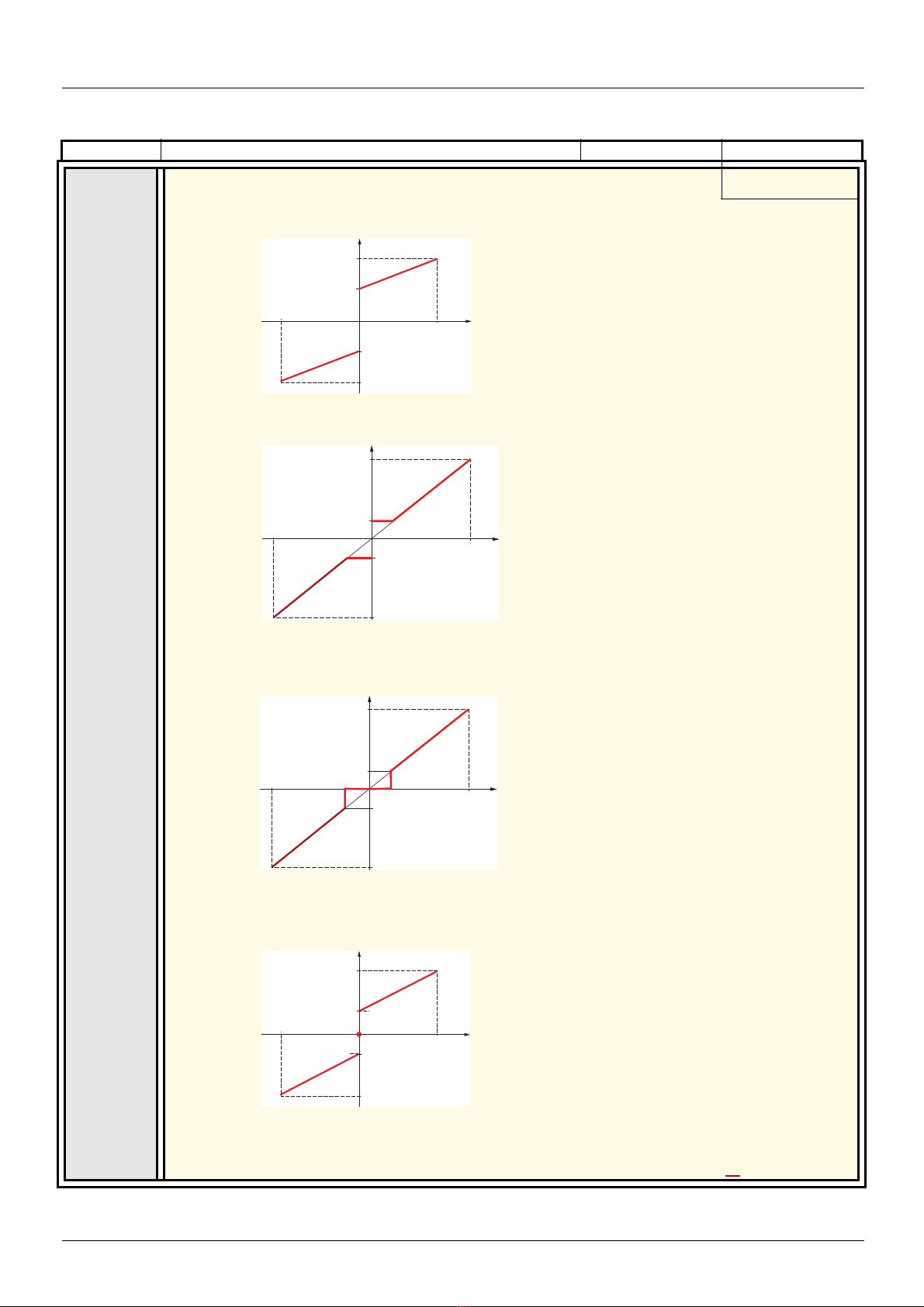
[1.5 INPUTS / OUTPUTS CFG] (I-O-)
Frequency
Reference
LSP
-100%
+100%
HSP
LSP
HSP
0%
Frequency
Reference
LSP
-100%
+100%
HSP
LSP
HSP
Frequency
Reference
LSP
-100%
+100%
HSP
LSP
HSP
0
Frequency
Reference
LSP
-100%
+100%
HSP
LSP
HSP
0%
Code Name/Description Adjustment range Factory setting
bSP
bSd
bLS
M [Reference template]
v [Standard] (bSd)
v [Pedestal] (bLS)
[Standard] (bSd)
At zero reference the frequency = LSP
At reference = 0 to LSP the frequency = LSP
bnS
bnS0
92 1755855 12/2009
v [Deadband] (bnS)
v [Deadband 0] (bnS0)
This parameter defines how the speed reference is taken into account, for analog inputs and Pulse
input only. In the case of the PID regulator, this is the PID output reference.
The limits are set by the [Low speed] (LSP) and [High speed] (HSP) parameters, page 44
At reference = 0 to LSP the frequency = 0
This operation is the same as [ Standard] (bSd),
except that in the following cases at zero
reference, the frequency = 0:
• The signal is less than [Min value], which is
greater than 0 (example 1 V on a 2
• The signal is greater than [Min value], which is
greater than [Max value] (example 11 V on a
10
- 0 V input).
If the input range is configured as
"bidirectional", operation remains identical to
[Standard] (bSd).
- 10 V input)

[1.5 INPUTS / OUTPUTS CFG] (I-O-)
Reference
100%
0%
[Min value]
(0%)
[Interm. point
X]
[Max value]
(100%)
Current
or
voltage
input
[Interm. point Y]
20 mA
or 10 V
Reference
100%
0%
[Min value]
(- 100%)
[Interm. point
X]
[Max value]
(100%)
Current
or
voltage input
[Interm. point Y]
- [Interm. point Y]
- 100%
- [Interm.
point X]
0%
20 mA
or 10 V
Delinearization: For analog inputs only
The input can be delinearized by configuring an inte rmediate point on the input/output curve of this input:
For range 0 V 100%
Note: For [Interm. point X], 0% corresponds to [Min value] and 100% to [Max value]
For range -100% V 100%
1755855 12/2009 93

[1.5 INPUTS / OUTPUTS CFG] (I-O-)
Code Name/Description Adjustment range Factory setting
AI1-
AI1A
AI1t
n10U
UIL1
UIH1
AI1F
AI1E
AI1S
10U
b [AI1 CONFIGURATION]
M [AI1 assignment]
Read-only parameter, cannot be configured.
It displays all the functions associated with input AI1 in order to check, for example, for compatibility
problems.
M [AI1 Type]
v [Voltage] (10U): Positive voltage input (negative values are interpreted as zero: the input is
unidirectional).
v [Voltage +/-] (n10U): Positive and negative voltage input (the input is bidirectional).
M [AI1 min value]
M [AI1 max value]
M [AI1 filter]
Interference filtering.
M [AI1 Interm. point X]
Input delinearization point coordinate.
• 0% corresponds to [AI1 min value] (UIL1).
• 100% corresponds to [AI1 max value] (UIH1).
M [AI1 Interm. point Y]
Output delinearization point coordinate (frequency reference).
[Voltage] (10U)
0 to 10.0 V 0 V
0 to 10.0 V 10.0 V
0 to 10.00 s 0 s
0 to 100% 0%
0 to 100% 0%
94 1755855 12/2009

[1.5 INPUTS / OUTPUTS CFG] (I-O-)
[Max value] + [Min value]
2
Code Name/Description Adjustment range Factory setting
AI2-
AI2A
AI2t
CrL2
UIL2
CrH2
UIH2
AI2F
AI2L
AI2E
10U
0A
POS
nEG
b [AI2 CONFIGURATION]
M [AI2 assignment]
Read-only parameter, cannot be configured.
It displays all the functions associated with input AI2 in order to check, for example, for compatibility
problems.
M [AI2 Type]
v [Voltage] (10U): Voltage input
v [Current] (0 A): Current input
M [AI2 min value]
The parameter can be accessed if [AI2 Type] (AI2t) = [Current] (0 A)
M [AI2 min value]
The parameter can be accessed if [AI2 Type] (AI2t) = [Voltage] (10U)
M [AI2 max. value]
The parameter can be accessed if [AI2 Type] (AI2t) = [Current] (0 A)
M [AI2 max. value]
The parameter can be accessed if [AI2 Type] (AI2t) = [Voltage] (10U)
M [AI2 filter]
Interference filtering.
M [AI2 range]
v [0 - 100%] (POS): Unidirectional input
v [+/- 100%] (nEG): Bidirectional input
Example: On a 0/10 V input
- 0 V corresponds to reference -100%
- 5 V corresponds to reference 0%
- 10 V corresponds to reference + 100%
M [AI2 Interm. point X]
Input delinearization point coordinate.
• 0% corresponds to [Min value] if the range is 0 V 100%.
[Current] (0 A)
0 to 20.0 mA 0 mA
0 to 10.0 V 0 V
0 to 20.0 mA 20.0 mA
0 to 10.0 V 10.0 V
0 to 10.00 s 0 s
[0 - 100%] (POS)
0 to 100% 0%
• 0% corresponds to if the range is -100% V + 100%.
• 100% corresponds to [Max value].
AI2S
1755855 12/2009 95
M [AI2 Interm. point Y]
Output delinearization point coordinate (frequency reference).
0 to 100% 0%
[1.5 INPUTS / OUTPUTS CFG] (I-O-)
[AI3 max. value] (CrH3) - [AI3 min. value]
(CrL3)
Code Name/Description Adjustment range Factory setting
AI3-
AI3A
AI3t
CrL3
CrH3
AI3F
AI3L
AI3E
0A
POS
nEG
b [AI3 CONFIGURATION]
Can be accessed if a VW3A3202 option card has been inserted
M [AI3 assignment]
Read-only parameter, cannot be configured.
It displays all the functions associated with input AI3 in order to check, for example, for compatibility
problems.
M [AI3 Type]
Read-only parameter, cannot be configured.
v [Current] (0 A): Current input
M [AI3 min. value]
M [AI3 max. value]
M [AI3 filter]
Interference filtering.
M [AI3 range]
v [0 - 100%] (POS): Unidirectional input
v [+/- 100%] (nEG): Bidirectional input
Example: On a 4 - 20 mA input
- 4 mA corresponds to reference -100%
- 12 mA corresponds to reference 0%
- 20 mA corresponds to reference + 100%
Since AI3 is, in physical terms, a bidi rectio nal i nput, t he [+/- 100%] (nEG) configuration must only be us ed
if the signal applied is unidirectional. A bidirecti onal signal is not compatible with a bidirectional
configuration.
M [AI3 Interm. point X]
Input delinearization point coordinate.
• 0% corresponds to [Min value] (CrL3) if the range is 0 V 100%.
[Current] (0 A)
0 to 20.0 mA 0 mA
0 to 20.0 mA 20.0 mA
0 to 10.00 s 0 s
[0 - 100%] (POS)
0 to 100% 0%
• 0% corresponds to if the ra nge is -100% V +100%.
• 100% corresponds to [AI3 max. value] (CrH3).
AI3S
96 1755855 12/2009
M [AI3 Interm. point Y]
Output delinearization point coordinate (frequency reference).
0 to 100% 0%

[1.5 INPUTS / OUTPUTS CFG] (I-O-)
[Max value] + [Min value]
2
Code Name/Description Adjustment range Factory setting
AI4-
AI4A
AI4t
CrL4
UIL4
CrH4
UIH4
AI4F
AI4L
AI4E
10U
0A
POS
nEG
b [AI4 CONFIGURATION]
Can be accessed if a VW3A3202 option card has been inserted
M [AI4 assignment]
Read-only parameter, cannot be configured.
It displays all the functions associated with input AI4 in order to check, for example, for compatibility
problems.
M [AI4 Type]
v [Voltage] (10U): Voltage input
v [Current] (0 A): Current input
M [AI4 min value]
The parameter can be accessed if [AI4 Type] (AI4t) = [Current] (0 A)
M [AI4 min value]
The parameter can be accessed if [AI4 Type] (AI4t) = [Voltage] (10U)
M [AI4 max value]
The parameter can be accessed if [AI4 Type] (AI4t) = [Current] (0 A)
M [AI4 max value]
The parameter can be accessed if [AI4 Type] (AI4t) = [Voltage] (10U)
M [AI4 filter]
Interference filtering.
M [AI4 range]
v [0 - 100%] (POS): Unidirectional input
v [+/- 100%] (nEG): Bidirectional input
Example: On a 0/10 V input
- 0 V corresponds to reference -100%
- 5 V corresponds to reference 0%
- 10 V corresponds to reference + 100%
M [AI4 Interm.point X]
Input delinearization point coordinate.
• 0% corresponds to [Min value] if the range is 0 V 100%.
[Voltage] (10U)
0 to 20.0 mA 0 mA
0 to 10.0 V 0 V
0 to 20.0 mA 20.0 mA
0 to 10.0 V 10.0 V
0 to 10.00 s 0 s
[0 - 100%] (POS)
0 to 100% 0%
• 0% corresponds to if the range is -100% V + 100%.
• 100% corresponds to [Max value].
AI4S
1755855 12/2009 97
M [AI4 Interm.point Y]
Output delinearization point coordinate (frequency reference).
0 to 100% 0%

[1.5 INPUTS / OUTPUTS CFG] (I-O-)
WARNING
UNINTENDED EQUIPMENT OPERATION
If the equipment switches to forced local mode (see page 244), the virtual i nput remains fixed at the l ast
value transmitted.
Do not use the virtual input and forced local mode in the same configuration.
Failure to follow these instructions can result in death or serious injury.
Code Name/Description Adjustment range Factory setting
AU1-
AIC1
nO
Mdb
CAn
nEt
APP
b [VIRTUAL AI1]
M [AI net. channel]
Virtual input.
This parameter can also be accessed in the [PID REGULATOR] (PId-)submenu page 177.
[No] (nO): Not assigned (in this case, the virtual input does not appear in the analog input assignment
parameters for the functions)
v [Modbus] (Mdb): Integrated Modbus
v [CANopen] (CAn): Integrated CANopen
v [Com. card] (nEt): Communication card (if inserted)
v [C.Insid. card] (APP): Controll er Inside card (if inserted)
Scale: the value 8192 transmitted by this input is equivalent to 10 V on a 10 V input.
[No] (nO)
98 1755855 12/2009

[1.5 INPUTS / OUTPUTS CFG] (I-O-)
Code Name/Description Adjustment range Factory setting
PLI-
PIA
PIL
PFr
PFI
b [RP CONFIGURATION]
Can be accessed if a VW3A3202 option card has been inserted
M [RP assignment]
Read-only parameter, cannot be configured.
It displays all the functions associated with the Pulse In input in order to check, for example, for compatibility
problems.
M [RP min value]
Frequency corresponding to the minimum speed
M [RP max value]
Frequency corresponding to the maximum speed
M [RP filter]
Interference filtering.
- 30.00 to 30.00 kHz 0
0 to 30.00 kHz 30.00 kHz
0 to 1000 ms 0
1755855 12/2009 99

[1.5 INPUTS / OUTPUTS CFG] (I-O-)
Reference
100 %
0
[Freq. min. value]
(EIL)
[Freq. max. value]
(EFr)
300 kHz
Reference
100 %
0
[Freq. min. value]
(EIL)
[Freq. max. value]
(EFr)
Frequency
input
Frequency
input
300 kHz
Reference
100 %
[Freq. min. value]
(EIL)
[Freq. max. value]
(EFr)
300 kHz
Frequency
input
0
Configuration of the encoder input serving as a reference, with a frequency
generator
This reference is not signed, therefore the directions of operation must be given via the control channel (logic inputs, for example).
Minimum and maximum values (input values):
The minimum value corresponds to a minimum reference of 0% and the maximum value to a maximum reference of 100%. The minimum
value may be greater than the maximum value. It may also be negative.
A reference can be obtained at zero frequency by assigning a negative value to the minimum value.
100 1755855 12/2009
[1.5 INPUTS / OUTPUTS CFG] (I-O-)
The encoder configuration can also be accessed in the [1.4 MOT OR CONTROL] (drC-) menu.
Code Name/Description Adjustment range Factory setting
IEn-
EnS
EnC
AAbb
Ab
A
nO
YES
dOnE
b [ENCODER CONFIGURATION]
The encoder parameters can only be accessed if the encoder card has been inserted, and the available
selections will depend on the type of encoder card used.
M [Encoder type]
The parameter can be accessed if an incremental encoder card has been in serted.
To be configured in accordance with the type of encoder used.
v [AABB] (AAbb): For signals A, A-, B, B-.
v [AB] (Ab): For signals A, B.
v [A] (A): For signal A. Value cannot be accessed if [Encoder usage] (EnU) page 102 = [Spd fdk reg.] (rEG).
M [Encoder check]
Checks the encoder feedback. See procedure page 80.
The parameter can be accessed if an encoder card has been inserted and if [Encoder usage] (EnU) page
102 is not [Speed ref.] (PGr).
v [Not done] (nO): Check not performed.
v [Yes] (YES): Activates monitoring of the encoder.
v [Done] (dOnE): Check performed successfully.
The check procedure checks:
- The direction of rotation of the encoder/motor
- The presence of signals (wiring continuity)
- The number of pulses/revolution
If a fault is detected, the drive locks in [Encoder fault] (EnF) fault mode.
[AABB] (AAbb)
[Not done] (nO)
1755855 12/2009 101
 Loading...