


Schneider Electric ION8800 User Manual

PowerLogic® ION8800
Energy & Power Quality Meter
Installation Guide
05/2007


Danger
This symbol indicates the presence of dangerous voltage within and outside the product enclosure
that may constitute a risk of electric shock, serious injury or death to persons if proper precautions
are not followed.
Caution
This symbol alerts the user to the presence of hazards that may cause minor or moderate injury to
persons, damage to property or damage to the device itself, if proper precautions are not followed.
Consult this document whenever this symbol is used on the meter, to determine the nature of the
potential hazard and any actions which need to be taken.
Note
This symbol directs the user’s attention to important installation, operating and maintenance
instructions.
Installation Considerations
Installation and maintenance of the ION 8800 meter should only be performed by qualified, competent personnel
that have appropriate training and experience with high voltage and current devices. The meter must be installed in
accordance with all local and national electrical codes.
If this equipment is used in a manner not specified by the manufacturer, the protection from electric shock, fire, etc.
provided by this equipment may be impaired.
DANGER
Failure to observe the following instructions may result in severe injury or death.
During normal operation of the ION 8800 meter, hazardous voltages are present on its connector pins,
and throughout the connected potential transformer (PT), current transformer (CT), direct connect without
PTs, digital (status) input, control power and external I/O circuits. PT and CT secondary circuits are capable
of generating lethal voltages and currents with their primary circuit energized. Follow standard safety precautions while performing any installation or service work (i.e. removing PT fuses, shorting CT
secondaries, etc).
Do not use digital output devices for primary protection functions. These include applications where the
devices perform energy limiting functions or provide protection of people from injury. Do not use the ION
8800
in situations where failure of the devices can cause injury or death, or cause sufficient energy to be
released that can start a fire. The meter can be used for secondary protection functions.
The ION 8800 meter’s chassis ground must be properly connected to a good earth ground for safety, and
for the noise and surge protection circuitry to function correctly. Failure to do so will void the warranty, and
create a risk of electric shock, injury or death.
When installing the meter, all voltage paths (measurement voltage and all auxiliary circuits such as the
power supply and the tariff control voltage) must be fused according to applicable local safety standards.
CAUTION
Observe the following instructions, or permanent damage to the meter may occur.
The ION 8800 meter offers a range of hardware options that affect input ratings. The ION 8800 meter’s
serial number label lists all equipped options. Applying current levels incompatible with the current inputs
will permanently damage the meter. This document provides installation instructions applicable to each
hardware option.
Do not HIPOT/Dielectric test the digital (status) inputs, digital outputs, power supply terminals or commu-
nications terminals. Refer to the label on the ION 8800 meter for the maximum voltage level the device
can withstand.
Replacing the meter battery with the wrong type or voltage rating could result in damage to the meter. Use
only a lithium LiSOCl2 battery with a rated voltage of 3.6 V, and the same construction as the original
battery, as a replacement.
3

Network Compatibility Notice for the Internal Modem
The internal modem in meters equipped with this option is compatible with the telephone systems of most countries
in the world. Use in some countries may require modification of the internal modem’s initialization strings. If problems
using the modem on your phone system occur, please contact Schneider Electric Technical Support.
Standards Compliance
Made by Power Measurement Ltd.
PowerLogic, ION, ION Enterprise, MeterM@il and Modbus are either trademarks or registered trademarks of
Schneider Electric.
Covered by one or more of the following patents:
U.S. Patent No's 7010438, 7006934, 6990395, 6988182, 6988025, 6983211, 6961641, 6957158,
6944555, 6871150, 6853978, 6825776, 6813571, 6798191, 6798190, 6792364, 6792337, 6751562,
6745138, 6737855, 6694270, 6687627, 6671654, 6671635, 6615147, 6611922, 6611773, 6563697,
6493644, 6397155, 6236949, 6186842, 6185508, 6000034, 5995911, 5828576, 5736847, 5650936,
D505087, D459259, D458863, D443541, D439535, D435471, D432934, D429655, D427533.
4

ION8800 Models
Feature Set Description
C
B
A
Available Options
Basic Tariff/Energy revenue meter
Feature Set C + EN50160 and IEC 61000-4-30 Class A compliant power
quality monitoring
Feature Set B + power quality analysis (waveforms and transient capture
with 1024 samples/cycle resolution)
Logging and
Recording
5 MB memory
10 MB memory
I/O Options
Ordering
Code
A
B
C
D
E
Before You Begin
Before installing the meter, familiarize yourself with the steps in this guide and
read the safety precautions presented on the “Installation Considerations”
page.
Current
Inputs
Low Current
(In=1A, 2A)
High Current
(In=5A)
8 digital Form A solid-state outputs
1 Form C mechanical relay
4 Form C solid-state outputs
8 digital Form A solid-state outputs
1 Form C mechanical relay
4 Form C solid-state outputs
8 digital Form A solid-state outputs
1 Form C mechanical relay
4 Form C solid-state outputs
1 Form C mechanical relay
4 Form C solid-state outputs
IRIG-B
1 Form C mechanical relay
4 Form C solid-state outputs
IRIG-B
Optical IEC 1107
RS-485 and optical IEC 1107
Communications Module (RS-485,
RS-232, modem, 10-Base-T Ethernet,
10-Base-FL Fiber Ethernet)
Outputs Digital Inputs Com
Communications Security
Standard
Hardware
locked
None
3 Low voltage None
3 High voltage None
3 Low voltage
3 High voltage
One RS-485 port on
Essailec connector
One RS-485 port on
Essailec connector
One RS-485 port on
Essailec connector
© 2007 Schneider Electric. All rights reserved. 5

Meter Overview
Meter Front (Cover Closed)
Operational
LEDs
Display
Optical
Communications
Port
Operational
LEDs
Display
Optical
Communications
Port
Slot-head
Screw
varh
Pulsing
Port
Cover
Seal
Meter Front (Cover Open)
Wh
Pulsing
Port
Navigation
Buttons
Slot-head
Screw
Sealed
Buttons
Navigation
Buttons
Battery
Cover
Slot-head
Screw
varh
Pulsing
Port
Cover
Seal
Wh
Pulsing
Port
Slot-head
Screw
Meter Back
Communications
Module Cover
Plate
Essailec
Connector
6 © 2007 Schneider Electric. All rights reserved.
Ground
Te rm i n al
Front Panel Button Functions
ALT/ENTER: Press this button once to enter ALT mode. Press and hold to enter
Setup mode. In Setup mode, press this button to accept changes.
NAVIGATION: Press the UP / DOWN arrow buttons to highlight menu items, or
increment / decrement numbers. Press and hold to shift cursor left and right.
DEMAND RESET: Press this button to reset all maximum demand registers. Not
accessible when cover is sealed.
TEST MODE: Press this button to enter Test Mode. Billable quantities do not
accumulate when meter is in Test Mode. Not accessible when cover is sealed.
ALT CONFIG: Press this button to enter the Alternate Configuration menu. Not
accessible when cover is sealed.
MASTER RESET: Press this button to reset meter quantities. Not accessible when
cover is sealed.
SPARE: This button is not currently implemented. Not accessible when cover is
sealed.
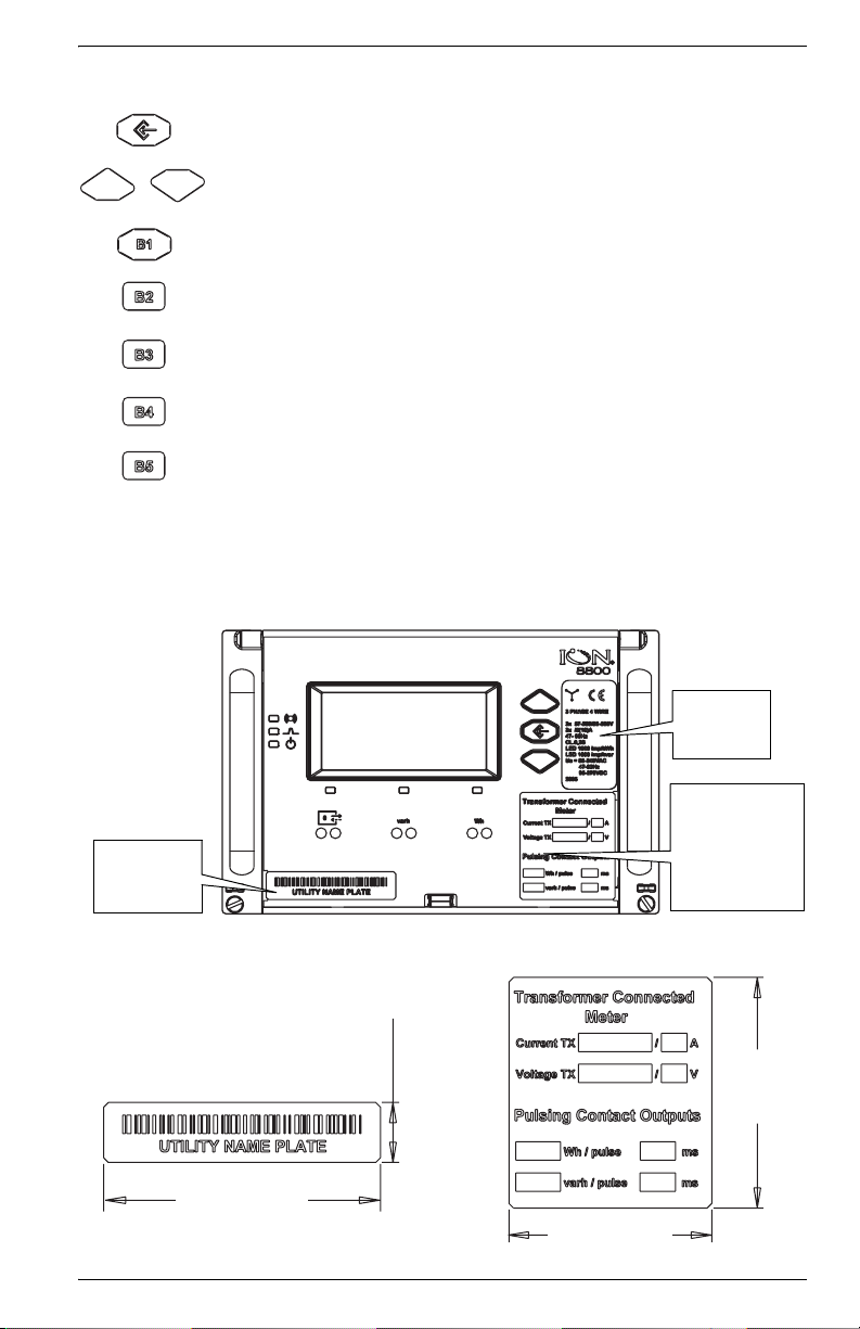
Meter Labels
Front of Meter (Cover Closed)
Voltage and
Current
Ratings
Transformer
Factors and
Energy Pulse
Nameplate
Removable
User Label
Weigh t Factor s
Removable
User Label
Removable User Labels
Insert user labels between bezel label and
plastic lid while cover is open.
50.0 mm
(1.97“)
13.0 mm
(0.51“)
60.0 mm
(2.36“)
44.0 mm
(1.73“)
© 2007 Schneider Electric. All rights reserved. 7

Unit Dimensions
Meter dimensions conform to DIN standard 43862.
132.2 mm
(5.21“)
Front View of Meter
190.5 mm
(7.50“)
202.1 mm
(7.96“)
4.6 mm
(0.18“)
M3 Thread
Screw
57.2 mm
(2.25“)
38.4 mm
(1.51“)
Side View of Meter
Front of Rack View
482.0 mm
(18.98“)
to fit 19 inch rack
461.0 - 469.0 mm
(18.15 - 18.46“)
260.0 mm
(10.24“)
111.8 mm
(4.40“)
132.5 mm
(5.22“)
3U high
8 © 2007 Schneider Electric. All rights reserved.

Essailec Connections
Voltage, current, power supply, I/O and communication connections are
made via the Essailec connector on the rear of the meter. Meters can be
ordered with multiple connector configurations.
Order Options B/C Circuit & Pinout Diagrams
This pinout drawing details the various pins
on the meter side of the connector. The
table below maps the pins to their
corresponding inputs and outputs in the
meter.
Code 07 Code 05 Code 03 Code 01
Code 13 Code 17 Code 15 Code 13
Rack
Meter
ABCDE
© 2007 Schneider Electric. All rights reserved. 9

Order Option A Circuit & Pinout Diagrams
This pinout drawing details the various pins
on the meter side of the connector. The
table below maps the pins to their
corresponding inputs and outputs in the
meter.
Code 07 Code 05 Code 03 Code 01
Rack
Code 15 Code 17 Code 15 Code 13
Meter
ABCDE
10 © 2007 Schneider Electric. All rights reserved.

Current
Measurement Inputs
Voltage
Measurement Inputs
Form A Outputs
Form C Solid-state
Relays
Unused
Form A Outputs
Form C Mechanical
Relay
Digital Inputs or
RS-485 Com
Power Supply Inputs
(AC/DC)
Order Options A/B/C Essailec Connector Arrangement
Meter Port Essailec Connector Pin Description
I11 A01 standard
I12 A1 standard
I21 A02 standard
I22 A2 standard
I31 A03 standard
I32 A3 standard
I41 A04 optional
I42 A4 optional
Uref B0 standard
U1 B1 standard
U2 B2 standard
U3 B3 standard
DO7 & DO8 K B4 standard; Common
DO5 & DO6 K B5 standard; Common
DO5 B6 standard; NO
DO6 B7 standard; NO
DO7 B8 standard; NO
DO8 B9 standard; NO
DO1 & DO2 K C0 standard; Common
DO1 C1 standard; NO
DO1 C2 standard; NC
DO2 C3 standard; NO
DO2 C4 standard; NC
DO3 & DO4 K C5 standard; Common
DO3 C6 standard; NO
DO3 C7 standard; NC
DO4 C8 standard; NO
DO4 C9 standard; NC
-D0 Unused
-D1 Unused
-D2 Unused
-D3 Unused
DO11 & DO12 K D4 standard; Common
DO9 & DO10 K D5 standard; Common
DO9 D6 standard; NO
DO10 D7 standard; NO
DO11 D8 standard; NO
DO12 D9 standard; NO
Alarm K E0 standard; Common
Alarm E1 standard; NO
Alarm E2 standard; NC
DI-SCOM (or RS-485
Shield)
DI1 (or RS-485 +) E6 RS-485 +
DI2 (or RS-485 -) E7 RS-485 DI3 (or unused) E8 standard
-E3 Unused
Power Supply N/- E4 Power Supply neutral (-)
Power Supply L/+ E9 Power Supply line (+)
E5 standard; Common
© 2007 Schneider Electric. All rights reserved. 11
 Loading...