Schneider Electric PF-305, PF-306, PF-307, PF-308 Data Sheet

PF-305, PF-306, PF-307, PF-308
Floating Differential Pressure
Electric Air Flow Switch
General Instructions
For use with Schneider Electric reversible control actuators and for controlling differential pressures, static pressures or air velocities in duct systems.
Other Applications:
•Static pressure control in hospital white rooms.
•Draft and exhaust damper control.
•Liquid level control in closed tanks.
All metal construction with conduit opening, for 13 mm (1/2") conduit fitting. Has barbed connections for high and low pressure connections for 9 mm (3/8") O.D. tubing. Unit has SPDT floating contact, rated for 1.0 amps at 24 volts. Unithas integral arc suppression. Ambient temperature range: -29 to 60°C (-20 to 140°F). Hascoded screw terminals. Mounts with diaphragm vertical on a vibration free surface. Dimensions: 130 mm (5-1/8") high, 120 mm (4-3/4") wide, and 111 mm (4-3/8") deep.
Option: None
ACCESSORIES |
|
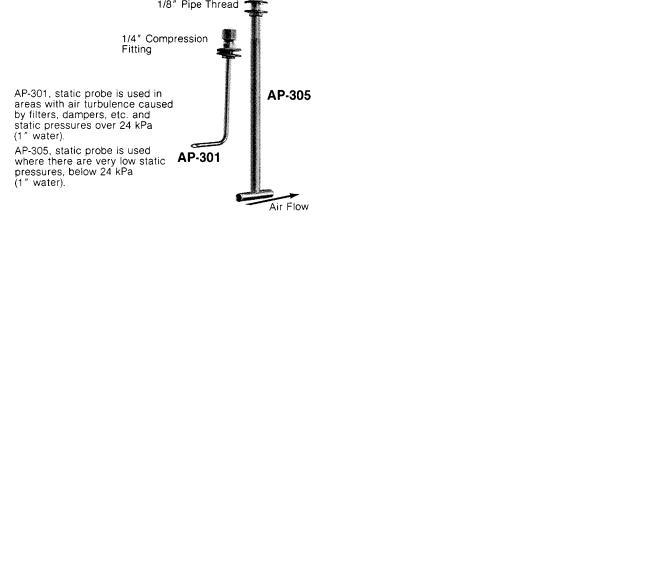
AP-301 |
Static probe for pressure .24 kPa (1" water) |
|
and up |
AP-305 |
Static probe for pressures below .24 kPa |
|
(1" water) |
AT-208 |
Duct mounting bracket for probes other than |
|
AP-301 and AP-305 |
INSTALLATION
Caution: These units are for use with air or non-combustible gases only.
Typical Actuators:
One Schneider Electric MP-300, -400, -2000 and -9700 series actuator directly. An AM-345 or AE-347 time delay relay is required for use with the MP-9200, -9400, -9600, and -9800 series actuator.
An SPDT floating switch action where “Common” makes to “Normally Closed” on a decrease in differential pressure between input ports, and to “Normally Open” on an increase in differential between input ports.
1.Select appropriate probes from Table 1.
2.Install probe. See Figure 4. Sampling probes should be located in areas of minimum air turbulence (6 to 8 duct diameters downstream from fan outlet, elbows, tees, ordampers). If this is not possible locate the probe tip as close to the center of the duct as possible.
3.Mount the unit with mounting screws supplied. Note: The diaphragm must be mounted in a vertical plane in a location free from vibration. See Figure 3 for mounting details.
4.Connect the probe(s) to thepressure taps using the 3/8" O.D. plastic tubing supplied.
5.Make all connections in accordance with job wiring diagrams and in compliance with national and local codes.
Figure-1 Typical Wiring.
Printed in U.S.A. 5/10 |
© Copyright 2010 Schneider Electric All Rights Reserved. |
F-17492-3 |

Table-1 Specification Table.
|
Differential Pressure |
Adjustable Null Span* |
Velocity Range M/S |
|
|||
Part Number |
Setpoint Range kPa |
At Minimum Setpoint |
At Maximum Setpoint |
(FPM) 21°C (70°F) |
Maximum Pressure |
||
|
(in. of water) |
kPa (in. of water) |
(in. of water) |
Air |
|
|
|
|
|
|
|
|
|
||
PF-305 |
-.12 to +.12 |
.01 to .03 |
.01 to .03 |
2 to 14 |
|
||
(-.5 to +.5) |
(.06 to .14) |
(.07 to .14) |
(400 to 2800) |
|
|||
|
|
||||||
|
|
|
|
|
|
||
PF-306 |
.04 to .32 |
.01 to .03 |
.03 to .06 |
9 to 23 |
Differential 3 kPa |
||
(.2 to 1.3) |
(.05 to.13) |
(.13 to .28) |
(1800 to |
4600) |
(12" Water) |
||
|
|||||||
PF-307 |
.27 to .87 |
.01 to .03 |
.02 to .07 |
22 to |
38 |
INPUT |
|
(1.1 to 3.5) |
(.06 to .17) |
(.11 to .31) |
(4200 to |
7500) |
7 kPa (28” Water) |
||
|
|||||||
|
|
|
|
|
|
|
|
PF-308 |
.79 to 2.48 |
.02 to .09 |
.06 to .19 |
37 to |
71 |
|
|
(3.2 to 10) |
(.12 to .4) |
(.24 to .8) |
(7200 to 14000) |
|
|||
|
|
||||||
*Min. null is with 127 μm (.005 in.) contact gap. Max null is 635 μM (.025 contact gap.
Probes 3 and 4 (see Figure 4) can be constructed from 1/4 inch O.D., copper, brass, or aluminum tubing. The ends of the probes should be cut square to the sides of the tube and deburred. Total pressure probe must have the sensing end bent at 90°approximately 25to 76 mm(1 to 3 inches) from the tip.
Figure-2 Optional Probes.
Figure-4
Figure-3 Mounting.
Table-2 Remote Mounting of Probe(s).
|
Static |
Velocitya |
Total |
Static |
Total |
Figure-5 |
High |
Probe 3 |
Probe 4 |
Probe 4 |
Probe 3 |
Probe 4 |
|
Press. |
|
|||||
Tapb |
|
|
|
|
|
|
Low |
|
Probe 3 |
— |
Probe 3 |
Probe 4 |
|
Press. |
— |
|
||||
Tap |
|
|
|
|
|
|
a Pilot can be used instead of two probes.
bHighest (absolute) pressure should be applied to high pressure tap.
=Differential.
2 |
© Copyright 2010 Schneider Electric All Rights Reserved. |
F-17492-3 |
 Loading...