


Schneider Electric Altivar31 User Manual
Altivar 31
Modbus
User’s manual
11/2009
#### |
#### |
#### |
1624597
www.schneider-electric.com

Contents
Presentation ________________________________________________________________________________________________ 3 Connection to RS485 bus ______________________________________________________________________________________ 4 Modbus protocol _____________________________________________________________________________________________ 8 Appendix: Non-standard RS485 schematics_______________________________________________________________________ 13
While every precaution has been taken in the preparation of this document, Schneider Electric SA assumes no liability for any omissions or errors it may contain, nor for any damages resulting from the application or use of the information herein.
The products described in this document may be changed or modified at any time, either in appearance or in their operation. Their description can in no way be considered contractual.
2 |
1624597 |
11/2009 |

Presentation
The Modbus socket on the Altivar 31 can be used for the following functions:
•Configuration
•Settings
•Control
•Monitoring
The ATV31 drive supports:
•The 2-wire RS485 physical layer
•The RTU transmission mode
This guide contains information on installation and describes the Modbus services available. The "communication variables" guide describes the operating modes, as well as the Altivar 31 variables and parameters which can be accessed via the communication bus.
1624597 11/2009 |
3 |

Connection to RS485 bus
Connection to ATV31
Connection accessories should be ordered separately (please consult our catalogues).
Connect the RJ45 cable connector to the ATV31 connector.
Pin out of the ATV31 RJ45 Connector
View from underneath
8........................1 |
Pin |
Signal |
1 |
CAN_H |
2 |
CAN_L |
3 |
CAN_GND |
4 |
D1 (1) |
5 |
D0 (1) |
6 |
Not connected |
7 |
VP (2) |
8 |
Common (1) |
(1) Modbus signals
(2) Supply for RS232 / RS485 converter or a remote terminal
Protection against interference
•Use the Schneider-Electric cable with 2 pairs of shielded twisted conductors (reference: TSXCSA100, TSXCSA200, TSXCSA500).
•Keep the Modbus cable from the power cables (30 cm minimum).
•Make any crossovers of the Modbus cable and the power cables at right-angles, if necessary.
•Connect the cable shielding to the ground of each device.
For more information, please refer to the TSX DG KBL E guide: "Electromagnetic compatibility of industrial networks and fieldbuses".
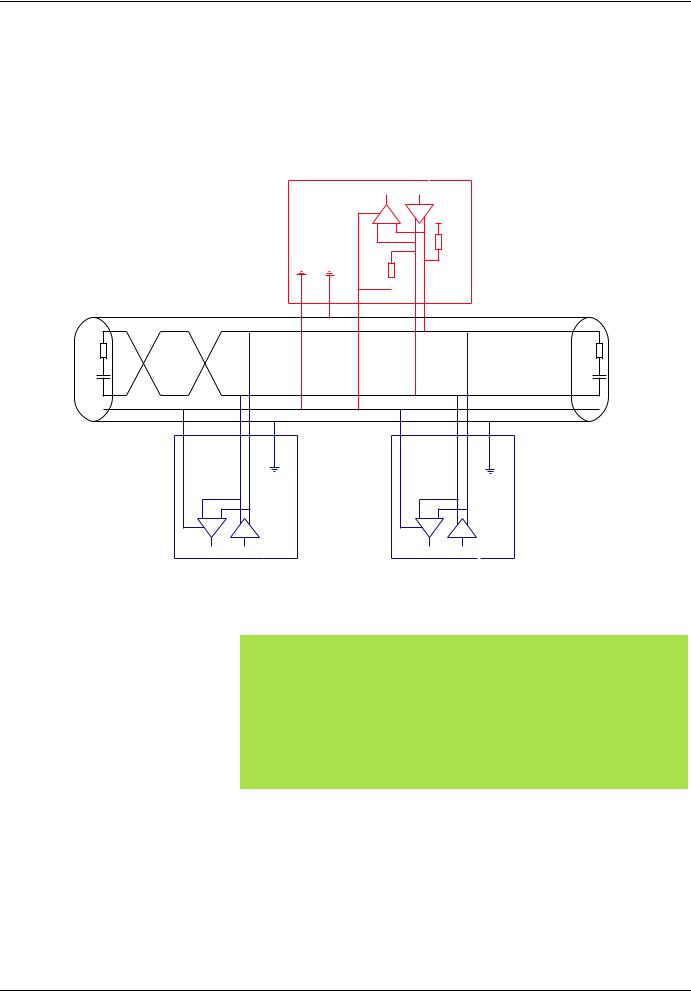
RS485 bus schematic
The RS485 standard allows variants of different characteristics:
•polarisation
•line terminator
•distribution of a reference potential
•number of slaves
•length of bus
The new Modbus specification published on the Modbus.org site in 2002 contains precise details of all these characteristics. They are also summarised in the next paragraph (Standard schematic). The new Schneider-Electric devices conform to this specification.
Some devices comply with earlier specifications. The two most widespread are described in the appendices:
•"Uni-Telway schematic" page 13
•"Jbus schematic" page 14
Requirements enabling different types of protocol to coexist are given in the appendix:
• "Mixed schematic" page 15
4 |
1624597 11/2009 |
Connection to RS485 bus
Standard schematic
The standard schematic corresponds to the Modbus specification published on the Modbus.org site in 2002 (Modbus_over_serial_line_V1.pdf, Nov 2002) and in particular to the schematic of the 2-wire multidrop serial bus.
The ATV31 drive conforms to this specification.
Schematic diagram:
Master
R |
T |
5 V |
|
650 Ω
650 Ω
 0 V
0 V
|
D1 |
120 Ω |
120 Ω |
1n F |
1n F |
|
D0 |
|
Common |
R |
T |
R |
T |
|
|
Slave 1 Slave n
|
|
Type of trunk cable |
Shielded cable with 1 twisted pair and at least a 3rd conductor |
Maximum length of bus |
1000 m at 19200 bps with the Schneider-Electric TSX CSAppp cable |
Maximum number of stations (without repeater) |
32 stations, ie. 31 slaves |
Maximum length of tap links |
• 20 m for one tap link |
|
• 40 m divided by the number of tap links on a multiple junction box |
Bus polarisation |
• One 450 to 650 Ω pulldown resistor at 5 V (650 Ω recommended) |
|
• One 450 to 650 Ω pulldown resistor at the Common (650 Ω recommended) |
|
This polarisation is recommended for the master. |
Line terminator |
One 120 Ω 0.25 W resistor in series with a 1nF 10 V capacitor |
Common polarity |
Yes (Common), connected to the protective ground at one or more points on the bus |
|
|
1624597 11/2009 |
5 |
Connection to RS485 bus
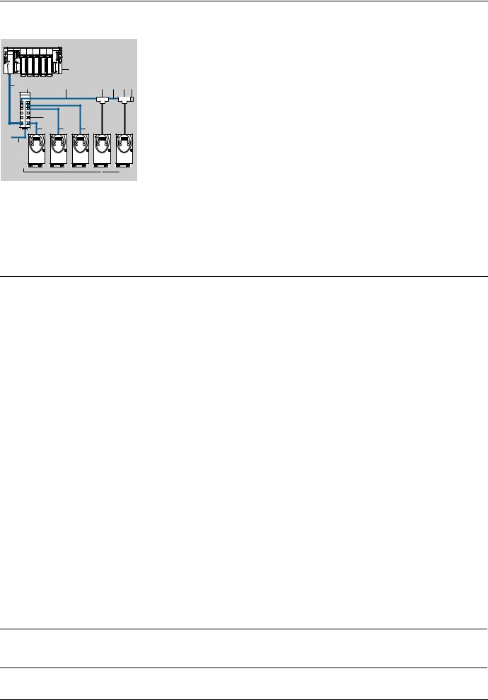
Connection via RJ45 wiring system
1 |
2 |
3 |
4 |
6 |
4 |
6 5 |
|
|
|
|
|
|
|
|
|
|
|
|
|
|
|
5 |
|
|
|
|
4 |
4 |
|
4 |
|
#### |
#### |
#### |
#### |
#### |
7 |
|
|
|
|
ATV 31
1Master (PLC, PC or communication module)
2Modbus cable depending on the type of master (see table)
3Modbus splitter block LU9 GC3
4Modbus drop cables VW3 A8 306 Rpp
5Line terminators VW3 A8 306 RC
6Modbus T-junction boxes VW3 A8 306 TFpp (with cable)
7Modbus cable (to another splitter block) TSX CSAp00
Connection accessories
Description |
|
|
|
Reference |
|
|
Modbus splitter block |
|
10 RJ45 connectors and 1 screw terminal |
LU9 GC3 |
|
||
Modbus T-junction boxes |
With integrated cable (0.3 m) |
VW3 A8 |
306 |
TF03 |
||
|
|
With integrated cable (1 m) |
VW3 A8 |
306 |
TF10 |
|
|
|
|
|
|
|
|
Line |
For RJ45 connector |
R = 120 |
Ω, C = 1 nF |
VW3 A8 |
306 RC |
|
terminators |
|
|
|
|
|
|
|
R = 150 |
Ω (specific to "Jbus schematic" page 14) |
VW3 A8 |
306 |
R |
|
|
|
|||||
Connecting cables
Description |
Length |
Connectors |
Reference |
|
|
m |
|
|
|
Cables for |
3 |
1 RJ45 connector and 1 stripped end |
VW3 A8 306 D30 |
|
Modbus bus |
|
|
|
|
0.3 |
2 RJ45 connectors |
VW3 A8 306 R03 |
||
|
||||
|
1 |
2 RJ45 connectors |
VW3 A8 306 R10 |
|
|
|
|
|
|
|
3 |
2 RJ45 connectors |
VW3 A8 306 R30 |
|
RS 485 double |
100 |
Supplied without connector |
TSX CSA 100 |
|
shielded twisted pair |
|
|
|
|
200 |
Supplied without connector |
TSX CSA 200 |
||
cables |
|
|
|
|
500 |
Supplied without connector |
TSX CSA 500 |
||
|
Type of master |
Master interface |
Modbus connection accessories for RJ45 wiring system |
|
|
|
Description |
Reference |
Twido PLC |
Adaptor or mini-DIN RS485 |
3 m cable fitted with a mini-DIN connector and an RJ45 |
TWD XCA RJ030 |
|
interface module |
connector |
|
|
|
|
|
|
Adaptor or screw terminal |
3 m cable fitted with an RJ45 connector and stripped at the |
VW3 A8 306 D30 |
|
RS485 interface module |
other end |
|
TSX Micro PLC |
Mini-DIN RS485 connector |
3 m cable fitted with a mini-DIN connector and an RJ45 |
TWD XCA RJ030 |
|
port |
connector |
|
|
|
|
|
|
PCMCIA card (TSX SCP114) |
Stripped cable |
TSX SCP CM 4030 |
TSX Premium PLC |
TSX SCY 11601 or |
Cable fitted with a SUB-D 25 connector and stripped at the |
TSX SCY CM 6030 |
|
TSX SCY 21601 module |
other end (for connection to the screw terminals of the |
|
|
(SUB-D 25 socket) |
LU9GC3 splitter block) |
|
|
PCMCIA card (TSX SCP114) |
Stripped cable |
TSX SCP CM 4030 |
Ethernet bridge |
Screw terminal RS485 |
3 m cable fitted with an RJ45 connector and stripped at the |
VW3 A8 306 D30 |
(174 CEV 300 10) |
|
other end |
|
Profibus DP gateway |
RJ45 RS485 |
1 m cable fitted with 2 RJ45 connectors |
VW3 P07 306 R10 |
(LA9P307) |
|
|
|
|
|
|
|
Fipio (LUFP1) or |
RJ45 RS485 |
0.3 m cable fitted with 2 RJ45 connectors or |
VW3 A8 306 R03 or |
Profibus DP (LUFP7) or |
|
1 m cable fitted with 2 RJ45 connectors or |
VW3 A8 306 R10 or |
DeviceNet (LUFP9) |
|
3 m cable fitted with 2 RJ45 connectors |
VW3 A8 306 R30 |
gateway |
|
|
|
Serial port PC |
Male SUB-D 9 RS232 serial |
|
port PC |
RS232/RS485 converter and |
TSX SCA 72 and |
3 m cable fitted with an RJ45 connector and stripped at the |
VW3 A8 306 D30 |
other end (for connection to the screw terminals of the |
|
LU9GC3 splitter block) |
|
6 |
1624597 11/2009 |
 Loading...