


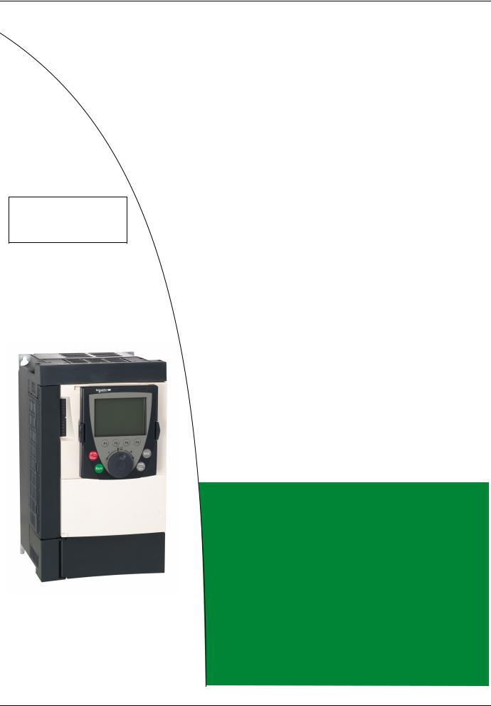
Schneider Electric Altivar61 User Manual
Altivar 61
Variable speed drives for synchronous motors and asynchronous motors
Installation Manual
03/2011
0.37 kW (0.5 HP) ... 45 kW (60 HP) / 200 - 240 V 0.75 kW (1 HP) ... 75 kW (100 HP) / 380 - 480 V 2.2 kW (3 HP) ... 7.5 kW (10 HP) / 500 - 600 V 2.2 kW (3 HP) ... 90 kW (100 HP) / 500 - 690 V
1760643
www.schneider-electric.com

Contents
Important information __________________________________________________________________________________________ 4 Before you begin______________________________________________________________________________________________ 5 Steps for setting up the drive ____________________________________________________________________________________ 6 Preliminary recommendations ___________________________________________________________________________________ 7 Drive ratings _________________________________________________________________________________________________ 9 Dimensions and weights_______________________________________________________________________________________ 12 Mounting and temperature conditions ____________________________________________________________________________ 13 Mounting in a wall-mounted or floor-standing enclosure ______________________________________________________________ 16 Installing the graphic display terminal_____________________________________________________________________________ 18 Position of the charging LED ___________________________________________________________________________________ 19 Installing option cards_________________________________________________________________________________________ 20 Installing the EMC plates ______________________________________________________________________________________ 22 Wiring precautions ___________________________________________________________________________________________ 23 Power terminals _____________________________________________________________________________________________ 25 Control terminals_____________________________________________________________________________________________ 27 Option terminals _____________________________________________________________________________________________ 29 Connection diagrams _________________________________________________________________________________________ 34 Use on IT system and “corner grounded” system____________________________________________________________________ 43 Electromagnetic compatibility, wiring _____________________________________________________________________________ 45
1760643 |
03/2011 |
3 |
Important information
PLEASE NOTE
Please read these instructions carefully and examine the equipment in order to familiarize yourself with the device before installing, operating or carrying out any maintenance work on it.
The following special messages that you will come across in this document or on the device are designed to warn you about potential risks or draw your attention to information that will clarify or simplify a procedure.
The addition of this symbol to a “Danger” or “Warning” safety label indicates that there is an electrical risk that will result in injury if the instructions are not followed.
This is a safety warning symbol. It warns you of the potential risk of injury. You must comply with all safety messages that follow this symbol in order to avoid the risk of injury or death.

 DANGER
DANGER indicates an imminently hazardous situation which, if not avoided, will result in death, serious injury or equipment damage.
 WARNING
WARNING indicates a potentially hazardous situation which, if not avoided, can result in death, serious injury or equipment damage.
 CAUTION
CAUTION indicates a potentially hazardous situation which, if not avoided, can result in injury or equipment damage.
PLEASE NOTE:
Only qualified personnel are authorized to carry out maintenance work on electrical equipment. Schneider Electric accepts no responsibility for the consequences of using this device. This document does not constitute an instruction manual for inexperienced personnel.
© 2006 Schneider Electric. All rights reserved.
4 |
1760643 |
03/2011 |

Before you begin
Read and observe these instructions before performing any procedure on this drive.
DANGER
RISK OF ELECTRIC SHOCK
•Read and understand this manual before installing or operating the Altivar 61 drive. Installation, adjustment, repair, and maintenance must be performed by qualified personnel.
•The user is responsible for compliance with all international and national electrical standards in force concerning protective grounding of all equipment.
•Many parts in this variable speed drive, including printed wiring boards, operate at line voltage. DO NOT TOUCH.
Use only electrically insulated tools.
•DO NOT touch unshielded components or terminal strip screw connections with voltage present.
•DO NOT short across terminals PA and PB or across the DC bus capacitors.
•Install and close all the covers before applying power or starting and stopping the drive.
•Before servicing the variable speed drive
-Disconnect all power.
-Place a “DO NOT TURN ON” label on the variable speed drive disconnect.
-Lock the disconnect in the open position.
•Disconnect all power including external control power that may be present before servicing the drive. WAIT 15 MINUTES to allow the DC bus capacitors to discharge. Then follow the DC bus voltage measurement procedure on page 19 to verify that the DC voltage is less than 45 V. The drive LEDs are not accurate indicators of the absence of DC bus voltage.
Failure to follow these instructions will result in death or serious injury.
 CAUTION
IMPROPER DRIVE OPERATION
•If the drive is not turned on for a long period, the performance of its electrolytic capacitors will be reduced.
•If it is stopped for a prolonged period, turn the drive on at least every two years for at least 5 hours to restore the performance of the capacitors, then check its operation. It is recommended that the drive is not connected directly to the line
voltage. The voltage should be increased gradually using an adjustable AC source.
Failure to follow these instructions can result in injury and/or equipment damage.
1760643 |
03/2011 |
5 |
Steps for setting up the drive
INSTALLATION
b 1 Receive and inspect the drive controller
vCheck that the catalog number printed on the label is the same as that on the purchase order
vRemove the Altivar from its packaging and check that it has not been damaged in transit
Steps 1 to 4 must be performed with the power off.
b 2 Check the line voltage
vCheck that the line voltage is compatible with the voltage range of the drive (see pages 9 and 10)
b 3 Mount the drive
vMount the drive in accordance with the instructions in this document
v Install any internal and external options
b 4 Wire the drive
vConnect the motor, ensuring that its connections correspond to the voltage
v Connect the line supply, after making sure that the power is off
v Connect the control
v Connect the speed reference
PROGRAMMING
v 5 Please refer to the
Programming Manual
6 |
1760643 |
03/2011 |
Preliminary recommendations
Handling/Storage
To protect the drive prior to installation, handle and store the device in its packaging. Ensure that the ambient conditions are acceptable.
WARNING
DAMAGED PACKAGING
If the packaging appears damaged, it can be dangerous to open it or handle it.
Take precautions against all risks when performing this operation.
Failure to follow this instruction can result in death or serious injury.
WARNING
DAMAGED EQUIPMENT
Do not operate or install any drive that appears damaged.
Failure to follow this instruction can result in death or serious injury.
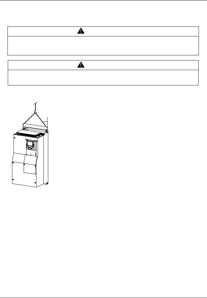
Handling on installation
45°
max.
ALTIVAR 61 drives up to ratings ATV61HD15M3X, ATV61HD18N4 and ATV61HU75S6X can be removed from their packaging and installed without a handling device.
A hoist must be used for higher ratings and for ATV61HpppY drives; for this reason, these drives all have lifting lugs. Follow the recommendations on the next page.
1760643 |
03/2011 |
7 |
Preliminary recommendations
Precautions
Read and observe the instructions in the Programming Manual.
 CAUTION
INCOMPATIBLE LINE VOLTAGE
Before turning on and configuring the drive, ensure that the line voltage is compatible with the supply voltage range shown on the drive nameplate. The drive may be damaged if the line voltage is not compatible.
Failure to follow this instruction can result in injury and/or equipment damage.
DANGER
UNINTENDED EQUIPMENT OPERATION
•Before turning on and configuring the Altivar 61, check that the PWR (POWER REMOVAL) input is deactivated (at state 0) in order to prevent unintended operation.
•Before turning on the drive, or when exiting the configuration menus, check that the inputs assigned to the run command are deactivated (at state 0) since they can cause the motor to start immediately.
Failure to follow these instructions will result in death or serious injury.
If the safety of personnel requires the prohibition of unwanted or unintended operation, electronic locking is performed by the Altivar 61's Power Removal function.
This function requires the use of connection diagrams conforming to category 3 of standard EN 954-1, ISO 13849-1 and safety integrity level 2 according to IEC/EN 61508.
The Power Removal function takes priority over any run command.
8 |
1760643 |
03/2011 |

Drive ratings
Single-phase supply voltage: 200…240 V 50/60 Hz
Three-phase motor 200...240 V
Motor |
|
Line supply (input) |
|
|
|
Drive (output) |
Altivar 61 |
||
Power |
|
Max. line current (2) |
Max. |
Apparent |
Max. inrush |
Max. |
Max. transient |
Catalog number (4)(5) |
|
indicated on |
|
|
prospective |
power |
current (3) |
available |
current (1) for |
|
|
at 200 V |
at 240 V |
|
|||||||
plate (1) |
|
line Isc |
|
|
nominal |
60 s |
|
||
|
|
|
|
|
|
||||
|
|
|
|
|
|
|
current |
|
|
|
|
|
|
|
|
|
In (1) |
|
|
kW |
HP |
A |
A |
kA |
kVA |
A |
A |
A |
|
0.37 |
0.5 |
6.9 |
5.8 |
5 |
1.4 |
9.6 |
3 |
3.6 |
ATV61H075M3 |
0.75 |
1 |
12 |
9.9 |
5 |
2.4 |
9.6 |
4.8 |
5.7 |
ATV61HU15M3 |
1.5 |
2 |
18.2 |
15.7 |
5 |
3.7 |
9.6 |
8 |
9.6 |
ATV61HU22M3 |
2.2 |
3 |
25.9 |
22.1 |
5 |
5.3 |
9.6 |
11.0 |
13.2 |
ATV61HU30M3 |
3 |
- |
25.9 |
22 |
5 |
5.3 |
9.6 |
13.7 |
16.4 |
ATV61HU40M3(6) |
4 |
5 |
34.9 |
29.9 |
22 |
7 |
9.6 |
17.5 |
21 |
ATV61HU55M3(6) |
5.5 |
7.5 |
47.3 |
40.1 |
22 |
9.5 |
23.4 |
27.5 |
33 |
ATV61HU75M3(6) |
Three-phase supply voltage: 200…240 V 50/60 Hz
Three-phase motor 200...240 V
Motor |
|
Line supply (input) |
|
|
|
Drive (output) |
Altivar 61 |
||
Power |
|
Max. line current (2) |
Max. |
Apparent |
Max. inrush |
Max. |
Max. transient |
Catalog number (4)(5) |
|
indicated on |
|
|
prospective |
power |
current (3) |
available |
current (1) for |
|
|
at 200 V |
at 240 V |
|
|||||||
plate (1) |
|
line Isc |
|
|
nominal |
60 s |
|
||
|
|
|
|
|
|
||||
|
|
|
|
|
|
|
current |
|
|
|
|
|
|
|
|
|
In (1) |
|
|
kW |
HP |
A |
A |
kA |
kVA |
A |
A |
A |
|
0.75 |
1 |
6.1 |
5.3 |
5 |
2.2 |
9.6 |
4.8 |
5.7 |
ATV61H075M3 |
1.5 |
2 |
11.3 |
9.6 |
5 |
4 |
9.6 |
8 |
9.6 |
ATV61HU15M3 |
2.2 |
3 |
15 |
12.8 |
5 |
5.3 |
9.6 |
11 |
13.2 |
ATV61HU22M3 |
3 |
- |
19.3 |
16.4 |
5 |
6.8 |
9.6 |
13.7 |
16.4 |
ATV61HU30M3 |
4 |
5 |
25.8 |
22.9 |
5 |
9.2 |
9.6 |
17.5 |
21 |
ATV61HU40M3 |
5.5 |
7.5 |
35 |
30.8 |
22 |
12.4 |
23.4 |
27.5 |
33 |
ATV61HU55M3 |
7.5 |
10 |
45 |
39.4 |
22 |
15.9 |
23.4 |
33 |
39.6 |
ATV61HU75M3 |
11 |
15 |
53.3 |
45.8 |
22 |
18.8 |
93.6 |
54 |
64.8 |
ATV61HD11M3X |
15 |
20 |
71.7 |
61.6 |
22 |
25.1 |
93.6 |
66 |
79.2 |
ATV61HD15M3X |
18.5 |
25 |
77 |
69 |
22 |
27.7 |
100 |
75 |
90 |
ATV61HD18M3X |
22 |
30 |
88 |
80 |
22 |
32 |
100 |
88 |
105.6 |
ATV61HD22M3X |
30 |
40 |
124 |
110 |
22 |
42.4 |
250 |
120 |
144 |
ATV61HD30M3X |
37 |
50 |
141 |
127 |
22 |
51 |
250 |
144 |
173 |
ATV61HD37M3X |
45 |
60 |
167 |
147 |
22 |
65 |
250 |
176 |
211 |
ATV61HD45M3X |
(1)These power ratings and currents are given for an ambient temperature of 50°C (122°F) at the factory-set switching frequency, used in continuous operation (factory-set switching frequency of 4 kHz for ATV61H 075M3 to D15M3X and 2.5 kHz for ATV61H D18M3X to D45M3X).
Above this factory setting, the drive will reduce the switching frequency automatically in the event of excessive temperature rise.
For continuous operation above the factory setting, derating must be applied to the nominal drive current in accordance with the curves on page 14.
(2)Current on a line supply with the “Max. prospective line Isc” indicated and for a drive without any external options. (3)Peak current on power-up for the max. voltage (240 V +10%).
(4)ATV61H 075M3 to D45M3X drives are available with or without a graphic display terminal. Catalog numbers for drives without a graphic display terminal have the letter Z added at the end, e.g.: ATV61H075M3Z. This option is not available for drives which operate in difficult environmental conditions (5).
(5)Drives with the S337 or 337 extension are designed for use in difficult environmental conditions (class 3C2 in accordance with IEC 721-3-3). They are supplied with a graphic display terminal.
(6)A line choke must be used (please refer to the catalog).
Inhibit the input phase loss fault (IPL) so that ATV61H 075M3 to U75M3 drives can operate on a single-phase supply (see the Programming Manual). If this fault is set to its factory configuration, the drive will stay locked in fault mode.
1760643 |
03/2011 |
9 |

Drive ratings
Three-phase supply voltage: 380…480 V 50/60 Hz
Three-phase motor 380...480 V
Motor |
|
Line supply (input) |
|
|
|
Drive (output) |
|
Altivar 61 |
||
Power indicated |
Max. line current (2) |
Max. |
Apparent |
Max. |
Max. available nominal |
Max. |
Catalog number |
|||
on plate (1) |
|
|
prospective |
power |
inrush |
current In (1) |
transient |
(4)(5) |
||
|
|
|
|
line Isc |
|
current (3) |
|
|
current (1) |
|
|
|
|
|
|
|
|
|
|
for 60 s |
|
|
|
at 380 V |
at 480 V |
|
|
|
at 380 V |
at 460 V |
|
|
kW |
HP |
A |
A |
kA |
kVA |
A |
A |
A |
A |
|
0.75 |
1 |
3.7 |
3 |
5 |
2.4 |
19.2 |
2.3 |
2.1 |
2.7 |
ATV61H075N4 |
1.5 |
2 |
5.8 |
5.3 |
5 |
4.1 |
19.2 |
4.1 |
3.4 |
4.9 |
ATV61HU15N4 |
2.2 |
3 |
8.2 |
7.1 |
5 |
5.6 |
19.2 |
5.8 |
4.8 |
6.9 |
ATV61HU22N4 |
3 |
- |
10.7 |
9 |
5 |
7.2 |
19.2 |
7.8 |
6.2 |
9.3 |
ATV61HU30N4 |
4 |
5 |
14.1 |
11.5 |
5 |
9.4 |
19.2 |
10.5 |
7.6 |
12.6 |
ATV61HU40N4 |
5.5 |
7.5 |
20.3 |
17 |
22 |
13.7 |
46.7 |
14.3 |
11 |
17.1 |
ATV61HU55N4 |
7.5 |
10 |
27 |
22.2 |
22 |
18.1 |
46.7 |
17.6 |
14 |
21.1 |
ATV61HU75N4 |
11 |
15 |
36.6 |
30 |
22 |
24.5 |
93.4 |
27.7 |
21 |
33.2 |
ATV61HD11N4 |
15 |
20 |
48 |
39 |
22 |
32 |
93.4 |
33 |
27 |
39.6 |
ATV61HD15N4 |
18.5 |
25 |
45.5 |
37.5 |
22 |
30.5 |
93.4 |
41 |
34 |
49.2 |
ATV61HD18N4 |
22 |
30 |
50 |
42 |
22 |
33 |
75 |
48 |
40 |
57.6 |
ATV61HD22N) |
30 |
40 |
66 |
56 |
22 |
44.7 |
90 |
66 |
52 |
79.2 |
ATV61HD30N4 |
37 |
50 |
84 |
69 |
22 |
55.7 |
90 |
79 |
65 |
94.8 |
ATV61HD37N4 |
45 |
60 |
104 |
85 |
22 |
62.7 |
200 |
94 |
77 |
112.8 |
ATV61HD45N4 |
55 |
75 |
120 |
101 |
22 |
81.8 |
200 |
116 |
96 |
139 |
ATV61HD55N4 |
75 |
100 |
167 |
137 |
22 |
110 |
200 |
160 |
124 |
192 |
ATV61HD75N4 |
(1)These power ratings and currents are given for an ambient temperature of 50°C (122°F) at the factory-set switching frequency, used in continuous operation (factory-set switching frequency of 4 kHz for ATV61H 075N4 to D30N4 drives, and 2.5 kHz for ATV61H D37N4 to D75N4).
Above this factory setting, the drive will reduce the switching frequency automatically in the event of excessive temperature rise. For continuous operation above the factory setting, derating must be applied to the nominal drive current in accordance with the curves on page 14.
(2)Current on a line supply with the “Max. prospective line Isc” indicated and for a drive without any external options. (3)Peak current on power-up for the max. voltage (480 V +10%).
(4)ATV61H 075N4 to D75N4 drives are available with or without a graphic display terminal. Catalog numbers for drives without a graphic display terminal have the letter Z added at the end, e.g.: ATV61H075N4Z. This option is not available for drives which operate in difficult environmental conditions (5).
(5)Drives with the S337 or 337 extension are designed for use in difficult environmental conditions (class 3C2 in accordance with IEC 721-3-3). They are supplied with a graphic display terminal.
10 |
1760643 |
03/2011 |
Drive ratings
Three-phase supply voltage: 500…600 V 50/60 Hz
Three-phase motor 500...600 V
Motor |
|
Line supply (input) |
|
Drive (output) |
|
Altivar 61 |
|
Power indicated on |
Max. line current (2) |
Max. |
Max. available |
|
Catalog number |
||
plate (1) |
|
|
|
prospective |
nominal current In (1) |
|
|
|
|
|
|
line Isc |
|
|
|
500 V |
575 V |
at 500 V |
at 600 V |
|
500 V |
575 V |
|
kW |
HP |
A |
A |
kA |
A |
A |
|
2.2 |
3 |
7.6 |
6.7 |
22 |
4.5 |
3.9 |
ATV61HU22S6X |
3 |
- |
9.9 |
10 |
22 |
5.8 |
- |
ATV61HU30S6X |
4 |
5 |
12.5 |
10.9 |
22 |
7.5 |
6.1 |
ATV61HU40S6X |
5.5 |
7.5 |
16.4 |
14.2 |
22 |
10 |
9 |
ATV61HU55S6X |
7.5 |
10 |
21.4 |
18.4 |
22 |
13.5 |
11 |
ATV61HU75S6X |
Three-phase supply voltage: 500…690 V 50/60 Hz
Three-phase motor 500...690 V
Motor |
|
|
Line supply (input) |
|
|
Drive (output) |
|
Altivar 61 |
||
Power indicated on |
|
Max. line current (2) |
|
Max. |
Max. available |
|
Catalog number |
|||
plate (1) |
|
|
|
|
|
prospective |
nominal current In (1) |
|
|
|
|
|
|
|
|
|
line Isc |
|
|
|
|
500 V |
575 V |
690 V |
at 500 V |
at 600 V |
at 690 V |
|
500 V |
575 V |
690 V |
|
kW |
HP |
kW |
A |
A |
A |
kA |
A |
A |
A |
|
2.2 |
3 |
3 |
5.2 |
4.4 |
5.2 |
22 |
4.5 |
3.9 |
4.5 |
ATV61HU30Y |
3 |
- |
4 |
6.8 |
- |
6.6 |
22 |
5.8 |
- |
5.8 |
ATV61HU40Y |
4 |
5 |
5.5 |
8.6 |
7.2 |
8.6 |
22 |
7.5 |
6.1 |
7.5 |
ATV61HU55Y |
5.5 |
7.5 |
7.5 |
11.2 |
9.5 |
11.2 |
22 |
10 |
9 |
10 |
ATV61HU75Y |
7.5 |
10 |
11 |
14.6 |
12.3 |
15.5 |
22 |
13.5 |
11 |
13.5 |
ATV61HD11Y |
11 |
15 |
15 |
19.8 |
16.7 |
20.2 |
22 |
18.5 |
17 |
18.5 |
ATV61HD15Y |
15 |
20 |
18.5 |
24 |
21 |
24 |
22 |
24 |
22 |
24 |
ATV61HD18Y |
18.5 |
25 |
22 |
29 |
24 |
27 |
22 |
29 |
27 |
29 |
ATV61HD22Y |
22 |
30 |
30 |
33 |
28 |
34 |
22 |
35 |
32 |
35 |
ATV61HD30Y |
30 |
40 |
37 |
48 |
41 |
41 |
22 |
47 |
41 |
43 |
ATV61HD37Y |
37 |
50 |
45 |
61 |
51 |
55 |
22 |
59 |
52 |
54 |
ATV61HD45Y |
45 |
60 |
55 |
67 |
57 |
63 |
22 |
68 |
62 |
62 |
ATV61HD55Y |
55 |
75 |
75 |
84 |
70.5 |
82 |
22 |
85 |
77 |
84 |
ATV61HD75Y |
75 |
100 |
90 |
110 |
92 |
102 |
22 |
104 |
99 |
104 |
ATV61HD90Y |
(1)These power ratings and currents are given for an ambient temperature of 50°C (122°F) at the factory-set switching frequency, used in continuous operation (factory-set switching frequency of 4 kHz for ATV61H U22S6X to U75S6X and ATV61H U30Y to D30Y drives, and 2.5 kHz for ATV61H D37Y to D90Y).
Above this factory setting, the drive will reduce the switching frequency automatically in the event of excessive temperature rise. For continuous operation above the factory setting, derating must be applied to the nominal drive current in accordance with the curves on page 14.
(2)Current on a line supply with the “Max. prospective line Isc” indicated and for a drive without any external options.
Note
The maximum transient current for 60 s corresponds to 120% of the maximum nominal current In.
1760643 |
03/2011 |
11 |
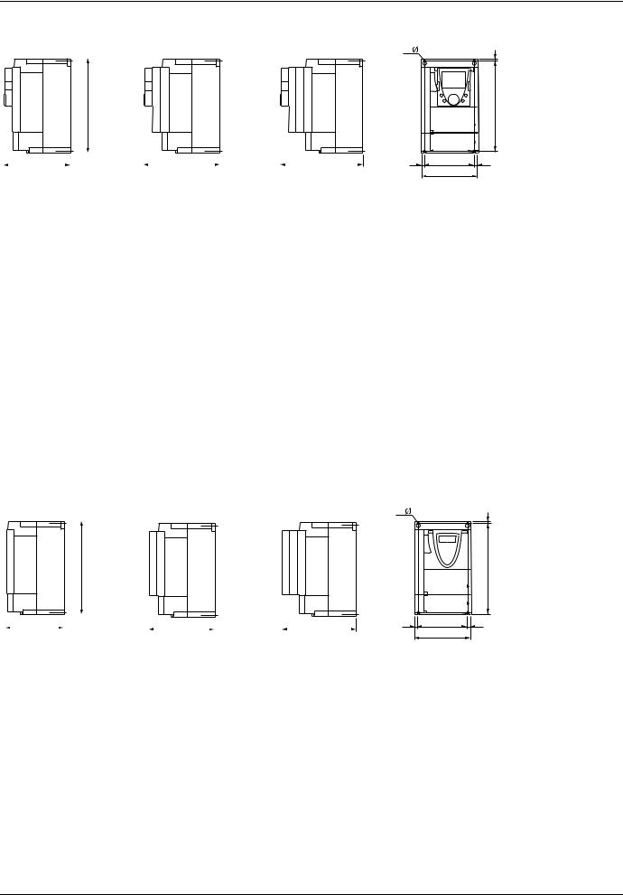
Dimensions and weights
With graphic display terminal
No option card |
|
1 option card (1) |
2 option cards (1) |
|
|
|
|
|
|
|
|
|
|
|
|
|
|||
|
|
|
|
|
|
|
|
|
|
|
|
|
|
|
|
|
|
|
|
|
|
ATV61H |
a |
b |
c |
c1 |
c2 |
G |
H |
h |
Ø |
For |
Weight |
|
mm |
mm |
mm |
mm |
mm |
mm |
mm |
mm |
mm |
screws |
kg |
|
(in.) |
(in.) |
(in.) |
(in.) |
(in.) |
(in.) |
(in.) |
(in.) |
(in.) |
|
(lb.) |
075M3, U15M3, |
130 |
230 |
175 |
198 |
221 |
113.5 |
220 |
5 |
5 |
M4 |
3 |
075N4, U15N4,U22N4 |
(5.12) |
(9.05) |
(6.89) |
(7.80) |
(8.70) |
(4.47) |
(8.66) |
(0.20) |
(0.20) |
|
(6.61) |
|
|
|
|
|
|
|
|
|
|
|
|
U22M3, U30M3, U40M3, |
155 |
260 |
187 |
210 |
233 |
138 |
249 |
4 |
5 |
M4 |
4 |
U30N4, U40N4 |
(6.10) |
(10.23) |
(7.36) |
(8.27) |
(9.17) |
(5.43) |
(9.80) |
(0.16) |
(0.20) |
|
(8.82) |
|
|
|
|
|
|
|
|
|
|
|
|
U55M3, U55N4, U75N4 |
175 |
295 |
187 |
210 |
233 |
158 |
283 |
6 |
5 |
M4 |
5.5 |
|
(6.89) |
(11.61) |
(7.36) |
(8.27) |
(9.17) |
(6.22) |
(11.14) |
(0.24) |
(0.20) |
|
(12.13) |
U75M3, D11N4 |
210 |
295 |
213 |
236 |
259 |
190 |
283 |
6 |
6 |
M5 |
7 |
U22S6X ... U75S6X |
(8.27) |
(11.61) |
(8.39) |
(9.29) |
(10.20) |
(7.48) |
(11.14) |
(0.24) |
(0.24) |
|
(15.43) |
|
|
|
|
|
|
|
|
|
|
|
|
D11M3X, D15M3X, |
230 |
400 |
213 |
236 |
259 |
210 |
386 |
8 |
6 |
M5 |
9 |
D15N4, D18N4 |
(9.05) |
(15.75) |
(8.39) |
(9.29) |
(10.20) |
(8.26) |
(15.20) |
(0.31) |
(0.24) |
|
(19.84) |
D18M3X, D22M3X, D22N4, |
240 |
420 |
236 |
259 |
282 |
206 |
403 |
11 |
6 |
M5 |
30 |
U30Y ... D30Y |
(9.45) |
(16.54) |
(9.29) |
(10.20) |
(11.10) |
(8.11) |
(15.87) |
(0.45) |
(0.24) |
|
(66.14) |
|
|
|
|
|
|
|
|
|
|
|
|
D30N4, D37N4 |
240 |
550 |
266 |
289 |
312 |
206 |
531.5 |
11 |
6 |
M5 |
37 |
|
(9.45) |
(21.65) |
(10.47) |
(11.38) |
(12.28) |
(8.11) |
(20.93) |
(0.45) |
(0.24) |
|
(81.57) |
D30M3X, D37M3X, D45M3X |
320 |
550 |
266 |
289 |
312 |
280 |
524 |
20 |
9 |
M8 |
37 |
|
(12.60) |
(21.65) |
(10.47) |
(11.38) |
(12.28) |
(11.02) |
(20.93) |
(0.79) |
(0.35) |
|
(81.57) |
D45N4, D55N4, D75N4, |
320 |
630 |
290 |
313 |
334 |
280 |
604.5 |
15 |
9 |
M8 |
45 |
D37Y ... D90Y |
(12.60) |
(24.80) |
(11.42) |
(12.32) |
(13.15) |
(11.02) |
(23.80) |
(0.59) |
(0.35) |
|
(99.21) |
Without graphic display terminal
No option card |
|
1 option card (1) |
2 option cards (1) |
|
|
|
|
b
c |
|
|
|
c1 |
|
|
c2 |
|
|
|
|
|
|||
|
|
|
|
|
|||
|
|
|
|
|
|||
|
|
|
|
|
|
|
|
4 x |
h |
|
H |
= |
G |
= |
|
a |
|
For a drive without a graphic display terminal, dimensions c, c1 and c2 in the table above are reduced by 26 mm (1.01 in.). The other dimensions are unchanged.
(1)For the addition of I/O extension cards, communication cards, or the “Controller Inside” programmable card.
12 |
1760643 |
03/2011 |

Mounting and temperature conditions
100 mm 3.94 in. |
u u |
u 100 mm u 3.94 in.
Install the drive vertically to ± 10°.
Do not place it close to heating elements.
Leave sufficient free space to ensure that the air required for cooling purposes can circulate from the bottom to the top of the unit.
Free space in front of the drive: 10 mm (0.39 in.) minimum
When IP20 protection is adequate, it is recommended that the protective cover on the top of the drive is removed as shown below.
Removing the protective cover
ATV61H 075M3 to D15M3X, ATV61H075N4 to D18N4 and ATV61H U22S6X to U75S6X
ATV61H D18M3X to D45M3X, ATV61H D22N4 to D75N4 and ATV61H U30Y to D90Y
Two types of mounting are possible:
Type A Free space u 50 mm (u 1.97 in.) on each side, with protective cover fitted mounting
u 50 mm |
u 50 mm |
u 1.97 in. |
u 1.97 in. |
Type B Drives mounted side by side, with the protective cover removed (the degree of protection becomes IP20) mounting
Type C Free space u 50 mm (u 1.97 in.) on each side, with protective cover removed (the degree of protection becomes IP20) mounting
u 50 mm |
u 50 mm |
u 1.97 in. |
u 1.97 in. |
1760643 |
03/2011 |
13 |
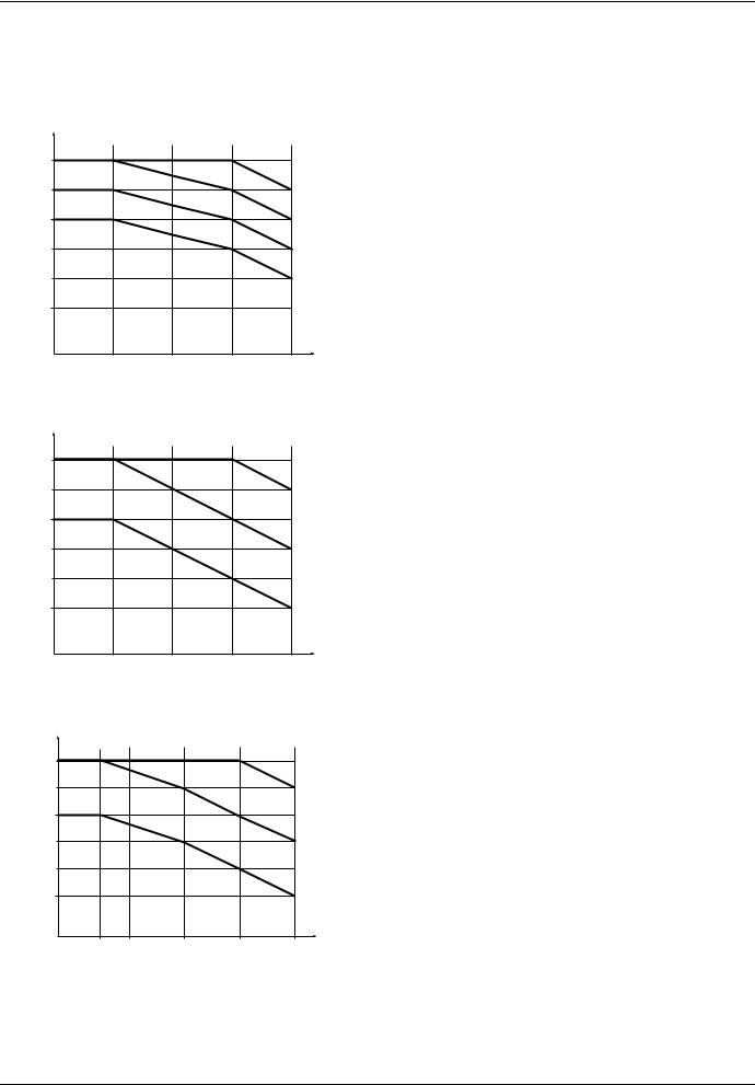
Mounting and temperature conditions
Derating curves
Derating curves for the drive current In as a function of the temperature, switching frequency and type of mounting.
ATV61H 075M3 to D15M3X and ATV61H 075N4 to D18N4 |
|||
I/In |
|
|
|
In = 100 % |
|
|
|
90 % |
|
|
40°C (104°F) mounting type B |
|
|
|
|
80 % |
|
|
40°C (104°F) mounting type A |
|
|
50°C (122°F) mounting type B |
|
|
|
|
|
70 % |
|
|
50°C (122°F) mounting type A |
|
|
|
|
60 % |
|
|
60°C (140°F) mounting types A and B |
50 % |
|
|
|
4 kHz |
8 kHz |
12 kHz |
16 kHz Switching frequency |
ATV61H D22N4 and ATV61H D30N4 (1) |
|
||
I/In |
|
|
|
In = 100 % |
|
|
|
90 % |
|
|
40°C (104°F) mounting types A and B |
|
|
|
|
80 % |
|
|
|
70 % |
|
|
50°C (122°F) mounting types A and B |
60 % |
|
|
|
50 % |
|
|
60°C (140°F) mounting types A and B |
4 kHz |
8 kHz |
12 kHz |
16 kHz Switching frequency |
ATV61H D18M3X to D45M3X and ATV61H D37N4 to D75N4 (1) |
|||
I/In |
|
|
|
|
In = 100 % |
|
|
|
|
90 % |
|
|
|
40°C (104°F) mounting types A and B |
80 % |
|
|
|
|
70 % |
|
|
|
50°C (122°F) mounting types A and B |
60 % |
|
|
|
|
50 % |
|
|
|
60°C (140°F) mounting types A and B |
2,5 kHz |
4 kHz |
8 kHz |
12 kHz |
16 kHz Switching frequency |
For intermediate temperatures (e.g. 55°C (131°F)), interpolate between two curves.
(1)Above 50°C (122°F), these drives must be equipped with a control card fan kit. Please refer to the catalog.
14 |
1760643 |
03/2011 |
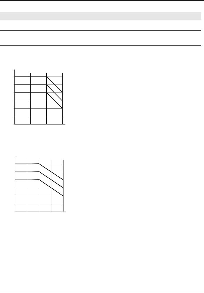
Mounting and temperature conditions
Derating for ATV61HpppS6X
Mounting type A and B:
ATV61HpppS6X drives can operate with a switching frequency 2,5…6kHz up to 50°C without derating.
Mounting type C:
ATV61HpppS6X drives can operate with a switching frequency 2,5…6kHz up to 60°C without derating For operation above 50°C (122°F), power supply voltage must be limited up to 600V+5%.
ATV61H U30Y to D30Y |
|
|
I/In |
|
|
In = 100 % |
|
|
90 % |
|
40°C (104°F) mounting type A |
80 % |
|
|
|
50°C (122°F) mounting types B and C |
|
70 % |
|
50°C (122°F) mounting type A |
60 % |
|
60°C (140°F) mounting types A, B and C |
50 % |
|
|
40 % |
|
|
2 kHz |
4 kHz |
6 kHz |
|
Switching frequency |
|
ATV61H D37Y to D90Y |
|
|
I/In |
|
|
In = 100 % |
|
|
90 % |
|
|
80 % |
40°C (104°F) mounting type A |
|
50°C (122°F) mounting types B and C |
||
|
||
70 % |
50°C (122°F) mounting type A |
|
60 % |
60°C (140°F) mounting types A, B and C |
|
50 % |
|
|
40 % |
4,9 kHz |
|
2,5 kHz |
||
Switching frequency |
||
For intermediate temperatures (e.g. 55°C (131°F)), interpolate between two curves.
1760643 |
03/2011 |
15 |
 Loading...