


Schneider Electric 66123, 66124 User Manual

Network Management Card & Modbus/Jbus
66123 User Manual
Network Management Teleservice Card
66124 User Manual
For Galaxy 7000 UPS and SSC unit
Network Management Card & Modbus/Jbus 34022321XT indice :AE Page 1/98
Network Management Teleservice Card
APC by Schneider Electric
www.apc.com

Contents
1
MGE GALAXY 7000 NETWORK MANAGEMENT CARD PRESENTATION............................................................................................. 5
1.1 C
1.2 P
1.3 S
1.4 D
1.5 S
1.6 C
1.7 E
1.8 M
1.9 T
2
2.1 H
2.2 EMC C
2.3 C
2.4 A
2.5 N
2.6 E
2.7 MIB (M
2.8 M
2.9 T
2.10 D
ONNECTING THE
ROTECTION OF THE COMPUTERS / SERVERS
UPERVISION OF THE
IRECT SENDING OF E-MAIL
ENDING TEXT MESSAGES
OMPATIBILITY WITH THE NETWORK MANAGEMENT SYSTEMS
NVIRONMENT SENSOR (OPTION
ODBUS/JBUS FOR
ELESERVICE FOR
TECHNICAL DATA....................................................................................................................................................................................9
ARDWARE CHARACTERISTICS
OMPATIBILITY
ONFIGURATION
DMINISTRATION
ETWORK
NVIRONMENT SENSOR
ANAGEMENT INFORMATION BASE
ODBUS/JBUS FOR
ELESERVICE FOR
EFAULT PARAMETERS
UPS
TO THE ETHERNET NETWORK
UPS
S OVER THE NETWORK
..................................................................................................................................................................... 8
(SMS)............................................................................................................................................................. 8
) .............................................................................................................................................................8
INMC 66123.............................................................................................................................................................8
NMTC 66124.............................................................................................................................................................. 8
................................................................................................................................................................. 9
............................................................................................................................................................................... 9
...................................................................................................................................................................................... 9
................................................................................................................................................................................... 10
............................................................................................................................................................................................. 10
..........................................................................................................................................................................10
)............................................................................................................................................... 10
INMC 66123........................................................................................................................................................... 11
NMTC 66124............................................................................................................................................................ 11
..........................................................................................................................................................................12
................................................................................................................................. 6
.............................................................................................................................................6
...................................................................................................................................... 7
(NMS) – T
RAP SENDING
................................................................................8
3
INSTALLATION NETWORK MANAGEMENT CARD & MODBUS/JBUS (INMC 66123)......................................................................... 13
3.1 U
3.2 I
3.3 I
3.4 S
4
4.1 U
4.2 I
4.3 I
4.4 S
4.5 L
5
5.1 C
5.2 T
6
6.1 O
6.2 UPS.....................................................................................................................................................................................................21
Network Management Card & Modbus/Jbus 34022321XT indice :AE Page 2/98
Network Management Teleservice Card
APC by Schneider Electric
www.apc.com
NPACKING AND CHECK ON CONTENTS
NDICATIONS
NSTALLATION IN THE
ENSOR INSTALLATION (OPTION
INSTALLATION NETWORK MANAGEMENT TELESERVICE CARD (NMTC 66124).............................................................................15
NPACKING AND CHECK ON CONTENTS
NDICATIONS
NSTALLATION IN THE
ENSOR INSTALLATION (OPTION
INE PHONE PORT
CONFIGURATION................................................................................................................................................................................... 18
ONFIGURE IP PARAMETERS
5.1.1 Your network is equipped with a DHCP server................................................................................................................................19
5.1.2 Your network is not equipped with a DHCP server........................................................................................................................... 20
EST AFTER CONFIGURATION
SUPERVISION AND ADMINISTRATION BY BROWSER ....................................................................................................................... 21
PTIMISING THE PERFORMANCE OF YOUR BROWSER
6.2.1 UPS properties page....................................................................................................................................................................... 21
.........................................................................................................................................................................................13
UPS.....................................................................................................................................................................14
.........................................................................................................................................................................................15
UPS.....................................................................................................................................................................16
................................................................................................................................................................................. 17
.................................................................................................................................................................. 18
................................................................................................................................................................. 20
................................................................................................................................................... 13
)............................................................................................................................................................ 14
................................................................................................................................................... 15
)............................................................................................................................................................ 16
................................................................................................................................ 21

6.2.1.1 "UPS" zone: general information on the UPS.......................................................................................................................... 22
6.2.1.2 Power Saving Mode representation (Efficiency Booster Mode)............................................................................................... 26
6.2.1.3 "UPS measurements”............................................................................................................................................................. 27
6.2.1.4 "UPS status" zone: Essential information................................................................................................................................ 28
6.2.1.5 Viewing the alarms.................................................................................................................................................................29
6.2.1.6 Viewing the “About your UPS” window.................................................................................................................................... 30
6.2.2 On-line help..................................................................................................................................................................................... 31
6.2.3 Shutdown parameters..................................................................................................................................................................... 32
6.2.4 Measurements.................................................................................................................................................................................34
6.2.5 Event log......................................................................................................................................................................................... 35
6.2.6 System log ...................................................................................................................................................................................... 36
6.3 N
6.4 C
6.5 E
OTIFICATION
6.3.1 Email Notification.............................................................................................................................................................................37
6.3.2 E-mail Message Settings.................................................................................................................................................................39
ONFIGURATION
6.4.1 Network settings.............................................................................................................................................................................. 41
6.4.2 System............................................................................................................................................................................................ 43
6.4.3 Notified Applications........................................................................................................................................................................ 44
6.4.4 Central shutdown configuration.......................................................................................................................................................46
6.4.5 Access control................................................................................................................................................................................. 47
6.4.6 Date and time.................................................................................................................................................................................. 49
6.4.7 Firmware upload..............................................................................................................................................................................50
NVIRONMENT SENSOR (OPTION
6.5.1 Characteristics.................................................................................................................................................................................51
6.5.2 Environment Status......................................................................................................................................................................... 52
6.5.3 Environment Settings...................................................................................................................................................................... 53
6.5.4 Log.................................................................................................................................................................................................. 55
....................................................................................................................................................................................... 37
.................................................................................................................................................................................... 40
) ...........................................................................................................................................................51
7
SERVER PROTECTION.......................................................................................................................................................................... 56
7.1 SET-
7.2 S
7.2.1 Backup time before initiating the shutdown procedure (Shutdown After - Shutdown Timer)............................................................. 57
7.2.2 Initiating the shutdown procedure when the battery autonomy ratio is lower than: (If remaining time ratio under)............................58
7.2.3 Shutdown when backup time is less than........................................................................................................................................ 58
7.2.4 Shutdown duration ..........................................................................................................................................................................58
8
8.1.1 Teleservice procedure..................................................................................................................................................................... 59
8.1.2 General overview ............................................................................................................................................................................59
9
9.1 C
9.2 C
9.2.1 Choice 1: Read Network settings..................................................................................................................................................... 62
9.2.2 Choice 2: Modify Network settings................................................................................................................................................... 62
9.2.3 Choice 3: Set Ethernet speed.......................................................................................................................................................... 63
9.3 C
9.4 C
UP OF THE SHUTDOWN PARAMETERS
HUTDOWN CRITERIA MANAGED BY THE NETWORK MANAGEMENT CARD
TELESERVICE........................................................................................................................................................................................ 59
CONFIGURATION VIA RS232................................................................................................................................................................ 61
HOICE 1: RESTART / RESET
HOICE 2: NETWORK CONFIGURATION
HOICE 3: LOST PASSWORD / SET LOGIN PASSWORD TO DEFAULT
HOICE 4: RETURN TO DEFAULT CONFIGURATION
................................................................................................................................................................. 61
............................................................................................................................................... 56
.................................................................................................. 57
................................................................................................................................................... 62
.......................................................................................................... 63
................................................................................................................................... 64
Network Management Card & Modbus/Jbus 34022321XT indice :AE Page 3/98
Network Management Teleservice Card
APC by Schneider Electric
www.apc.com

10 MODBUS/JBUS INSTALLATION & USE................................................................................................................................................ 65
10.1 I
10.2 A
10.3 M
NSTALLATION
10.1.1 RS232 link configuration and connection..................................................................................................................................... 65
10.1.2 RS485 link configuration and connection..................................................................................................................................... 66
10.1.2.1
10.1.2.2
10.1.2.3
10.1.3 Configuration of the JBUS/MODBUS communication parameters............................................................................................... 72
10.1.3.1
10.1.3.2
10.1.3.3
10.1.3.4
10.1.3.5
10.1.3.6
DDITIONAL WEB PAGES
ODBUS REGISTER MAP
10.3.1 Detailled status table...................................................................................................................................................................76
10.3.2 Measurement table.....................................................................................................................................................................78
10.3.3 Environnement Sensor Table...................................................................................................................................................... 79
10.3.3.1
10.3.3.2
10.3.3.3
10.3.4 Examples of Modbus register map.............................................................................................................................................. 81
10.3.4.1
10.3.4.2
10.3.4.3
10.3.4.4
10.3.4.5
10.3.4.6
10.3.4.7
10.3.4.8
10.3.4.9
....................................................................................................................................................................................... 65
RS485 connection..............................................................................................................................................................66
RS485 link configuration for 2 wires connexion .................................................................................................................. 68
RS485 link configuration for 4 wires connexion .................................................................................................................. 70
Choice 1: Display Jbus settings..........................................................................................................................................73
Choice 2: Modify Jbus settings........................................................................................................................................... 73
Choice 3: Display Jbus diagnostics.................................................................................................................................... 73
Choice 4: Reset Jbus diagnostics....................................................................................................................................... 73
Choice 5: Return to Jbus Default Configuration..................................................................................................................74
Choice 6: Display Jbus frames........................................................................................................................................... 74
....................................................................................................................................................................... 75
........................................................................................................................................................................ 76
Sensor Status table............................................................................................................................................................79
Sensor Measurements table...............................................................................................................................................79
Sensor customisation table (RO)........................................................................................................................................80
Global overview.................................................................................................................................................................. 81
UPS on AC Normal input.................................................................................................................................................... 82
UPS on Battery ..................................................................................................................................................................83
Low Battery Warning..........................................................................................................................................................84
UPS on Bypass due to End of battery runtime....................................................................................................................85
UPS on Bypass due to manual order.................................................................................................................................. 86
UPS on Manual Bypass......................................................................................................................................................87
UPS running Power Saving Mode...................................................................................................................................... 88
Communication lost............................................................................................................................................................ 89
11 APPENDICES.......................................................................................................................................................................................... 90
11.1 T
11.2 SNMP
12 GLOSSARY.............................................................................................................................................................................................97
Network Management Card & Modbus/Jbus 34022321XT indice :AE Page 4/98
Network Management Teleservice Card
APC by Schneider Electric
www.apc.com
ABLES OF ALARMS AND EVENTS
11.1.1 Table of alarms and UPS events................................................................................................................................................. 90
11.1.2 Table of system alarms............................................................................................................................................................... 92
OBJECTS
11.2.1 MGE MIB.................................................................................................................................................................................... 93
11.2.2 Table des TRAPS : (1.3.6.1.4.1.705.1.11)................................................................................................................................... 96
.................................................................................................................................................................................... 93
...........................................................................................................................................................90

1 MGE Galaxy 7000 Network Management card presentation
MGE Galaxy 7000 Network Solution:
provides information on events concerning the supply of power to the computers connected to your computer network,
carries out automatic shutdown of computer systems and monitors all the UPSs connected to the network.
Network Management Cards acquire information on the operation status of the UPS systems and provide monitoring of these systems by means
of an ETHERNET network from any SNMP administration station or Web browser.
They also supply alarms to the “MGE Network Shutdown Modules” to trigger shutdown or other automatic actions for protected servers.
Network Management Cards are compatible with:
the "MGE Enterprise Power Management" supervision.
The “InfraStruXure Central” unit
As illustrated in the picture below, MGE Network Solution provides these 3 main functions:
supervision of the UPSs over the Network,
protection of the computers,
connexion of the UPS to the Network.
Network Management Card & Modbus/Jbus 34022321XT indice :AE Page 5/98
Network Management Teleservice Card
APC by Schneider Electric
www.apc.com

1.1 Connecting the UPS to the Ethernet network
This function can be performed through the network Cards inserted in the UPS (Network Management Card).
The Network Management Card:
manages communication with the UPS (as well as local protection of the machine on which Proxy is installed),
periodically accesses the information concerning the UPS,
makes this information available to the connected applications (Network Shutdown Modules, Web Browser, Network Management Systems,
Enterprise Power Manager), ISX Central, Bulding Management System,
sends notifications on certain events
Operation may be in standard secure mode (the default mode) or in SSL secure mode (Secure Socket Layer SSL).
1.2 Protection of the computers / servers
This function is performed by the Network Shutdown Module installed on each of the servers to be protected.
Note that the Shutdown Module is available on several Operating Systems.
The Network Shutdown Module:
Continuously waits for information from the Network Management Card connected to the UPS.
Warns administrators and users if AC power fails and proceeds with graceful system shutdown before the end of battery backup power is
reached.
Network Management Card & Modbus/Jbus 34022321XT indice :AE Page 6/98
Network Management Teleservice Card
APC by Schneider Electric
www.apc.com
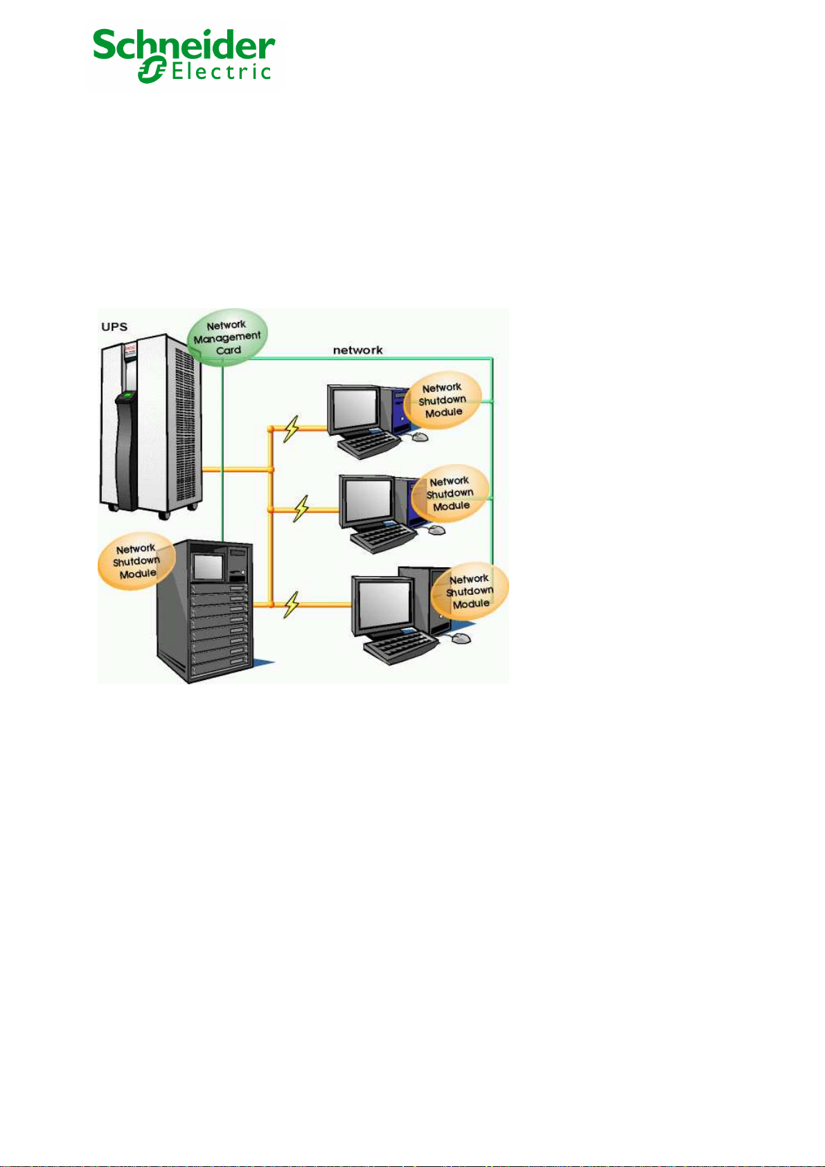
1.3 Supervision of the UPSs over the network
Depending on your needs, you can either use:
Your Internet browser to monitor each UPS, as Management Card includes a Web server.
Your company’s standard Network Management System (HP-Openview, CA Unicenter, HP Insight Manager, IBM Tivoli Netview). To simplify
integration of MGE Galaxy 7000 UPSs, you can use one of the Network Management System Kits for MGE devices. These kits are available on
the Management Pac 2 CD-ROM. (ref 66923)
The MGE supervisor "Enterprise Power Manager"
Set up the Network Management Card (see user manual).
Install and configure the Network Shutdown Module on all machines that are to be protected by the UPS.
The software components for each platform and the user manuals are on the Solution-Pac-2 CD or are available for download on the
www.mgeups.com Web site, in the “Download” section.
Network Management Card & Modbus/Jbus 34022321XT indice :AE Page 7/98
Network Management Teleservice Card
APC by Schneider Electric
www.apc.com

1.4 Direct sending of E-mail
When a UPS event occurs, the Network Management Card can directly notify up to 4 intranet or extranet addresses by e-mail (see E-mail
Notification and E-mail message settings)
1.5 Sending text messages (SMS)
The card offers the possibility of redirecting UPS alarms to an e-mail server. The format of these e-mails is compatible with mobile telephone e-
mail/SMS transfer systems proposed by ISPs. The format to be used depends on the service provider. For example, sms.0660256585@votre-
login.activmail.net (text messages).
1.6 Compatibility with the Network Management Systems (NMS) – Trap sending
The Network Management Cards are compatible with the major Network Management Systems (IBM Tivoli, CA Unicenter, HP Insight
Manager). The Management-Pac 2 offering includes the necessary SNMP plug-ins to allow an easy integration in the NMS. Events are
notified by SNMP trap.
1.7 Environment Sensor (option)
The Environment Sensor (66846) solution comprises a box to be connected to the Card Settings port of the Network Management Cards.
Environment Sensor enables measurement of temperature and humidity around the UPS, consideration of external alarms via 2 dry contacts
and notification of alarms according to pre-programmed thresholds. (see Environmen Status and Environment Configuration)
1.8 Modbus/Jbus for INMC 66123
The Modbus/Jbus hexadecimal (MODBUS RTU) communication protocol is used in slave mode. The system provides a communication channel
with an RS485 or RS232 interface.
1.9 Teleservice for NMTC 66124
The Teleservice card allow the UPS Remote Monitoring feature from the APC by Schneider TLS Center.
This feature manages remotely UPS alarms, UPS diagnostic, UPS Monitroing and Monthly Reporting.
Network Management Card & Modbus/Jbus 34022321XT indice :AE Page 8/98
Network Management Teleservice Card
APC by Schneider Electric
www.apc.com

2 Technical data
2.1 Hardware characteristics
Dimensions
Dimensions (L x l x H) 132 x 66 x 42 mm
Weight (gr) 70 g.
Storage
Storage temperature -10°C to 70°C
Ambient conditions
Operating temperature 0°C to 40°C
Ambient humidity 90% RH max without condensation
RoHS 100% compatible
2.2 EMC Compatibility
When correctly installed and used in accordance with the manufacturer's instructions, the Network Management Card complies with the following
standards:
Safety for ATI: IEC/EN 60950-1 2005
EMC: EN 61000-6-2 (2005), EN 61000-6-3 (2006).
As per European directives:
Low voltage: 2006/95/EEC.
EMC: 2004/108/EEC.
2.3 Configuration
The user can configure the card with one of the following means:
Web browser
Local serial link (network parameters)
BOOTP/DHCP (network parameters)
Network Management Card & Modbus/Jbus 34022321XT indice :AE Page 9/98
Network Management Teleservice Card
APC by Schneider Electric
www.apc.com

2.4 Administration
Up to 35 workstations protected by Network Shutdown Modules - Central or local configuration.
Up to 5 browsers connected at the same time (3 in SSL).
• Minimum recommended browser versions: Internet Explorer 6.x / 7.0, Mozilla Firefox 1.5 / 2.0 / 3.0
E-mail sending configurable according to UPS alarms and transmission of a periodical report.
Protection by encrypted password.
Protection by secure SSL connection.
Saving of logs in the non-volatile memory.
Languages available:
INMC 66123 : English / French / Spanish / German / Italian
NMTC 66124 : English
On-line help in English available for each page.
Card firmware updated via the network
2.5 Network
Fast ETHERNET 10/100 Mbits compatibility with auto-negotiation on the RJ45 outlet.
The used ports are:
BootP DHCP UDP 68 , 67
HTML TCP 80
SSL TCP 443
NSM in connected mode TCP 5000
SMTP 25
SNMP V1 161
TRAP SNMP 162
2.6 Environment sensor
Temperature measurement from 0 to 70°C with +/- 1°C accuracy
Measurement of humidity from 0 to 100% with +/- 6% accuracy
Min / max time-stamped function for temperature and humidity
Choice of temperature readings in Celsius or Fahrenheit
High and low thresholds, hysteresis and offset adjustable via Web interface
Possibility of notification of status changes by e-mail, SMS or SNMP trap
Position detection of 2 dry contacts (maximum sensor/contact distance: 20 m)
Name and status of each configurable contact
Recording of events and measurements in the card log
Possibility of shutting down the installation in the event of a threshold being exceeded or on opening / closure of a dry contact
Connection to the card with straight CAT5 RJ45 network cables (maximum card/sensor distance: 20 m)
Hot installation
2.7 MIB (Management Information Base)
Compatible with MIB MGE V1.8 adapted for Galaxy 7000.
The list of objects managed can be found in the
Network Management Card & Modbus/Jbus 34022321XT indice :AE Page 10/98
Network Management Teleservice Card
APC by Schneider Electric
www.apc.com
chapter 8.2.

2.8 Modbus/Jbus for INMC 66123
The Modbus/Jbus hexadecimal (MODBUS RTU) communication protocol is used in slave mode. The system provides a communication channel
with an RS485 or RS232 interface.
Note:
2 wires or 4 wires RS485 link are available.
Warning:
RS232 and RS485 communication ports cannot be used together.
JBUS/MODBUS communication is operational 2 minutes after the startup of the card.
The Modbus Register map is presented in chapter 7.4.
2.9 Teleservice for NMTC 66124
The Teleservice card allow the UPS Remote Monitoring feature from the APC by Schneider TLS Center.
This feature manages remotely UPS alarms, UPS diagnsoitc, UPS Monitroing and Montly Reporting.
See chapter 8.
Network Management Card & Modbus/Jbus 34022321XT indice :AE Page 11/98
Network Management Teleservice Card
APC by Schneider Electric
www.apc.com

2.10 Default parameters
Function Parameter Default value Possible value
Network IP address 172.17.16.16 Network IP address
Subnet mask 255.255.0.0 Network IP address
Gateway Address 0.0.0.0 Network IP address
BOOTP/DHCP Enabled Active / Deactivated
Firmware Upload Enabled Active / Deactivated
SMTP server smtpserver 49 characters maximum
System UPS Contact Computer Room Manager 49 characters maximum
UPS Location Computer Room 31 characters maximum
History log interval (sec.) 60 10 to 99999 sec.
Environment log interval (sec.) 300 10 to 99999 sec.
Default Language English English / French / Spanish /
German / Italian
Manager table empty 50 maximum
Access control User name MGEUPS 10 characters maximum
Password MGEUPS 10 characters maximum
Community name read public 49 characters maximum
Trap port 161 Non configurable
Date and time Date and time adjustment Manual adjustment
Serial link Speed 9600 baud Non configurable
Data bits 8 Non configurable
Stop bits 1 Non configurable
Parity without Non configurable
Flow control without Non configurable
Modbus/jbus
JBUS/MODBUS communication - Baud rate
- Parity
- Slave number
RS232 link
RS485 link - Termination - No termination - With or without (2 or 4 wires)
Teleservice - TLS settings via RS232 Menu - TLS for 1 UPS and Sensor
- Link connection in transmit
data (Tx) or receive data (Rx)
- 9600 bauds
- without parity
- Slave nr 1
- Rx on pin 1
- Tx on pin 3
feature available
Manual adjustment
- 1200, 2400, 4800, 9600
- Without parity, even parity
- 1 to FF (hexadecimal)
- Rx on pin 1
- Tx on pin 3
TLS up to 9 UPS
(1UPS/NMTC+ 9 UPS/INMC)
Network Management Card & Modbus/Jbus 34022321XT indice :AE Page 12/98
Network Management Teleservice Card
APC by Schneider Electric
www.apc.com

3 Installation Network Management Card & Modbus/Jbus (INMC 66123)
3.1 Unpacking and check on contents
The installation kit contents:
A Network Management Card & Modbus/Jbus (66123)
A serial communication cable for configuration (3402226700)
Installation manual (34022308)
3.2 Indications
Network Management Card & Modbus/Jbus 34022321XT indice :AE Page 13/98
Network Management Teleservice Card
APC by Schneider Electric
www.apc.com

Ethernet port
LED Colour Activity Description
ACT Green ◗ Off ◗ Card not connected to the network.
100M Orange ◗ Off ◗ Port operating at 10Mbits/s.
◗ On ◗ Port operating at 100Mbits/s.
Service port (Settings/Sensor)
LED Colour Activity Description
UPS Green ◗ Off ◗ Card startup in progress.
Data ◗ On ◗ Communication with UPS in progress
RS232 Orange ◗ Off ◗ Configuration menu is active
◗ On ◗ Normal operation. Configuration
◗ Flashing ◗ Communication with the Environment
◗ On
◗ Flashing
◗ Flashing
◗ Card connected to the network but
without activity
◗ Port is active in receiving /
transmission
◗ Normal operation.
Communication with the UPS is
operational
menu is deactived
Sensor (option).
3.3 Installation in the UPS
The Network Management Card (66123) can be "hot" installed in the MGE Galaxy 7000 UPS or SSC unit.
Note the card's MAC address prior to insertion
Connect the ETHERNET cable
Insert and tighten the card's retaining screws
Wait 3 min.; the card is completely operational when the green UPS Data LED flashes continuously
3.4 Sensor installation (option)
The Environment sensor is available as an option on the Network Management Card. SKU number is 66846.
The sensor allows remote monitoring of the UPS's environment through regular measurements: temperature, humidity, status of two external
contacts. It also enables notification of alarms (e-mail, trap SNMP) according to pre-programmed thresholds.
It is connected to the Service port (Settings/Sensor) directly on the Network Management Card with a standard Ethernet cable (20 meters
maximum).
Recognition is automatic. Supervision and configuration are performed via a menu that can be accessed directly from the home page.
Network Management Card & Modbus/Jbus 34022321XT indice :AE Page 14/98
Network Management Teleservice Card
APC by Schneider Electric
www.apc.com

4 Installation Network Management Teleservice Card (NMTC 66124)
4.1 Unpacking and check on contents
The installation kit contents:
A Network Management Teleservice Card (66124)
A serial communication cable for configuration (3402226700)
One phone cable for teleservice (3402226800)
One installation manual (34003976EN)
4.2 Indications
Network Management Card & Modbus/Jbus 34022321XT indice :AE Page 15/98
Network Management Teleservice Card
APC by Schneider Electric
www.apc.com

Ethernet port
LED Colour Activity Description
ACT Green ◗ Off ◗ Card not connected to the network.
100M Orange ◗ Off ◗ Port operating at 10Mbits/s.
◗ On ◗ Port operating at 100Mbits/s.
Service port (Settings/Sensor)
LED Colour Activity Description
UPS Green ◗ Off ◗ Card startup in progress.
Data ◗ On ◗ Communication with UPS in progress
RS232 Orange ◗ Off ◗ Configuration menu is active
◗ On ◗ Normal operation. Configuration
◗ Flashing ◗ Communication with the Environment
Phone port
◗ On
◗ Flashing
◗ Flashing
◗ Card connected to the network but
without activity
◗ Port is active in receiving /
transmission
◗ Normal operation.
Communication with the UPS is
operational
menu is deactived
Sensor (option).
LED Colour Activity Description
UPS Green ◗ Off ◗ Card not connected to phone network
Data
◗ Flashing ◗ Port is sending/receiving
CD Orange ◗ Off ◗ Modem is not connected
◗ On ◗ Modem is connected
◗ Flashing ◗ Modem is connecting
◗ On
◗ Card connected to phone network,
but no activity
4.3 Installation in the UPS
The Network Management Teleservice Card (66124) can be "hot" installed in the MGE Galaxy 7000 UPS or SSC unit.
Note the card's MAC address prior to insertion
Connect the ETHERNET cable
Insert and tighten the card's retaining screws
Wait 3 min.; the card is completely operational when the green UPS Data LED flashes continuously
For Teleservice installation, the NMTC card must be installed in the SSC unit.
4.4 Sensor installation (option)
The Environment sensor is available as an option on the Network Management Card. SKU number is 66846.
The sensor allows remote monitoring of the UPS's environment through regular measurements: temperature, humidity, status of two external
contacts. It also enables notification of alarms (e-mail, trap SNMP) according to pre-programmed thresholds.
It is connected to the Service port (Settings/Sensor) directly on the Network Management Card with a standard Ethernet cable (20 meters
maximum).
Recognition is automatic. Supervision and configuration are performed via a menu that can be accessed directly from the home page.
Network Management Card & Modbus/Jbus 34022321XT indice :AE Page 16/98
Network Management Teleservice Card
APC by Schneider Electric
www.apc.com

4.5 Line Phone Port
Telephone connexion for the teleservice application.
Network Management Card & Modbus/Jbus 34022321XT indice :AE Page 17/98
Network Management Teleservice Card
APC by Schneider Electric
www.apc.com

5 Configuration
5.1 Configure IP parameters
Once the card has started:
Connect one end of the cable (3402226700) to the Service port.
If the environment sensor was previously connected, the card must be restarted in order to access the configuration menu.
Connect the other end of the cable to the COM port (IOIOI) of a PC.
Launch a HyperTerminal™ type emulator with the following configuration:
NMTC INMC
Speed: 38400 Speed: 9600
Data bits: 8 Data bits: 8 toto
Parity: none Parity: none
Stop bits: 1 Stop bits: 1
Flow control: none Flow control: none
"Locally reproduce the characters entered" option: deactivated.
Enter MGEUPS or mgeups. The main menu is displayed:
Network Management Card & Modbus/Jbus 34022321XT indice :AE Page 18/98
Network Management Teleservice Card
APC by Schneider Electric
www.apc.com

5.1.1 Your network is equipped with a DHCP server
The card is configured by default with this service activated.
The card automatically collects IP parameters.
To know the IP parameters, type 2, the next menu is displayed:
----------------------------------------------------------------------------Network settings
---------------------------------------------------------------------------- 1 : Read Network settings
2 : Modify Network settings
3 : Set Ethernet speed
0 : Exit
-----------------------------------------------------------------------------
Then type 1. The menu is displayed:
Network configuration :
MAC address : 00:06:23:00:1F:8F
Mode : Static IP
IP address : 172.17.21.94
Subnet mask : 255.255.248.0
Gateway : 172.17.17.1
Note the IP address.
To exit, enter 0 then 0. The card is operational.
Note: As long as the card is not connected to the network, it continuously attempts to make connection. Once the connection has been
established, the operational mode presented in the table above becomes effective.
Network Management Card & Modbus/Jbus 34022321XT indice :AE Page 19/98
Network Management Teleservice Card
APC by Schneider Electric
www.apc.com

5.1.2 Your network is not equipped with a DHCP server
In the main menu enter 2, then 2 again. The menu is displayed:
Follow the instructions and enter the static IP parameters.
At the end of the menu, wait for the "Done" message to be displayed indicating that the IP parameters have been saved.
----------------------------------------------------------------------------Network settings
---------------------------------------------------------------------------- 1 : Read Network settings
2 : Modify Network settings
3 : Set Ethernet speed
0 : Exit
----------------------------------------------------------------------------For each of the following questions, you can press <Return> to select the value
shown in braces, or you can enter a new value.
Should this target obtain IP settings from the network?[N] N
Static IP address [172.17.21.94]? 172.17.21.21
Static IP address is 172.17.21.21
Subnet Mask IP address [255.255.248.0]? 255.255.255.0
Subnet Mask IP address is 255.255.255.0
Gateway address IP address [172.17.17.1]? 172.17.17.1
Gateway address IP address is 172.17.17.1
Wait during your new configuration is saved ...
Reset the card to take into account the new configuration.
Return to the main menu and enter 1 then 2.
The card restarts with the new IP parameters.
5.2 Test after configuration
To check that the Network Management Card is operational after installation and configuration.
From a station connected to the same subnet as the card, open a web browser and enter the IP address of the card in the address field.
Network Management Card & Modbus/Jbus 34022321XT indice :AE Page 20/98
Network Management Teleservice Card
APC by Schneider Electric
www.apc.com

6 Supervision and administration by browser
On a computer equipped with a Web browser (Internet Explorer, FireFox or Netscape recommended), enter the address initialised previously
in the Installation chapter (e.g. http://172.17.16.16.)
The "UPS properties" home page is displayed.
6.1 Optimising the performance of your browser
To view status changes on the UPS in real time, the browser must be configured so that it automatically refreshes all the objects on the
current page.
Example on IE 6 / IE 7: Tools / Internet Options / General / Parameters menu, tick Every time this page is visited and validate.
6.2 UPS
6.2.1 UPS properties page
This page is automatically refreshed every 10 seconds
From this page, access to the main UPS information is available thanks to the combo box (see screen copy below).
The different choices are the following ones:
“UPS Status”: (chosen by default) this page gives instant access to the essential information about your UPS.
“UPS Alarms”: to view the list of current alarms.
“About your UPS”: provides information on the UPS and the card, in particular, the model range and software version.
These different pages are detailed in the following chapters.
Network Management Card & Modbus/Jbus 34022321XT indice :AE Page 21/98
Network Management Teleservice Card
APC by Schneider Electric
www.apc.com

6.2.1.1 "UPS" zone: general information on the UPS.
Indication of the picture and generic name of the UPS range
Computer room: Customised name of your system.
You can change this name on the "System" page.
UPS status icon :
The various icons showing the status of the UPS are:
Normal operation
Alarm present. This icon links directly to the alarm
Animated synoptic: An animated synoptic gives a global overview of the UPS current operating mode.
The synoptic drawing depends on the UPS topology. The different drawings are described in the table below.
page.
Loss of communication with the UPS
UPS with automatic and manual bypass
UPS without automatic bypass
SSC Static Switch Cabinet
Note: In case of loss of communication with the UPS, all the elements of the synoptic are grey.
The various elements of the synoptic are the following ones:
Network Management Card & Modbus/Jbus 34022321XT indice :AE Page 22/98
Network Management Teleservice Card
APC by Schneider Electric
www.apc.com
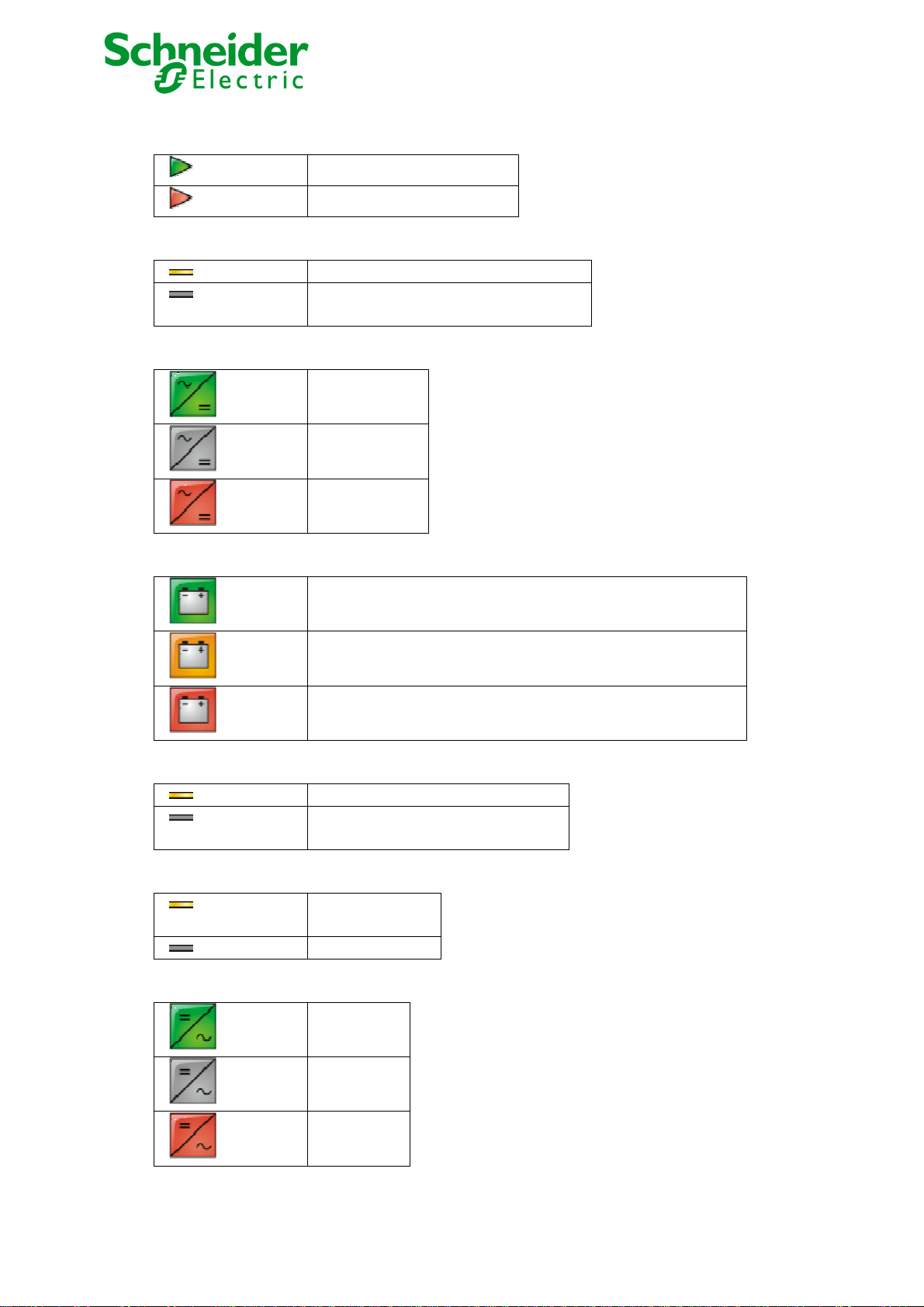
AC Normal Input :
AC Normal Flow :
AC to DC Converter:
Battery :
In tolerances
Out of tolerances
AC to DC converter powered by AC Normal
AC to DC converter not powered by AC
Normal
Powered
Not powered
Internal failure
Remaining capacity > 50%
Battery Output Flow :
DC to AC Converter Input flow :
DC to AC Converter :
Remaining capacity < 50%
Battery to be checked (battery test result)
DC to AC converter powered by battery
DC to AC converter not powered by
battery
Energy flow
present
No energy flow
Powered
Not powered
Internal
failure
Network Management Card & Modbus/Jbus 34022321XT indice :AE Page 23/98
Network Management Teleservice Card
APC by Schneider Electric
www.apc.com

DC to AC Converter Output :
AC Bypass Input :
AC Automatic Bypass Flow :
Energy flow
present
No energy flow
In tolerances
Out of tolerances
Energy flow present
No energy flow
Network Management Card & Modbus/Jbus 34022321XT indice :AE Page 24/98
Network Management Teleservice Card
APC by Schneider Electric
www.apc.com
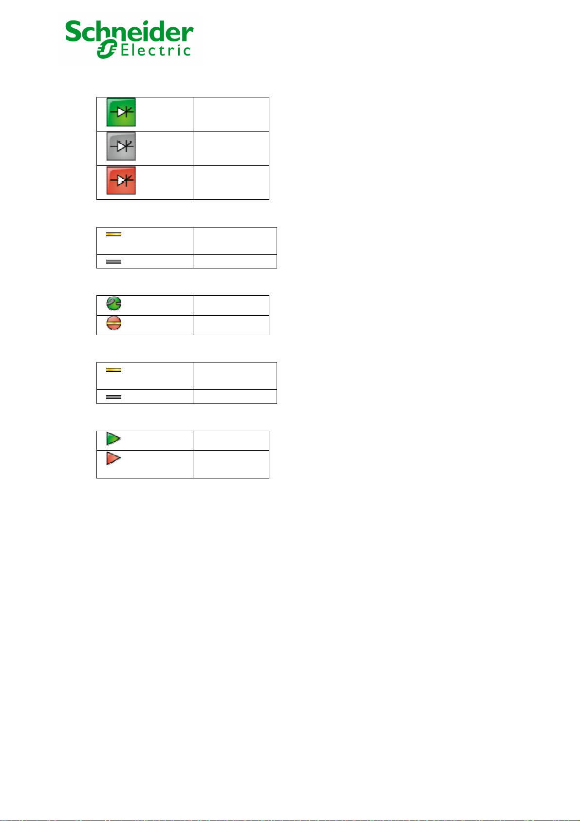
AC Automatic Bypass Status :
AC Manual Bypass Flow :
AC Manual Bypass Status :
AC Output Flow :
AC Output :
Powered
Not powered
Internal failure
Energy flow
present
No energy flow
Open
Closed
Energy flow
present
No energy flow
Load powered
Load not
powered
Network Management Card & Modbus/Jbus 34022321XT indice :AE Page 25/98
Network Management Teleservice Card
APC by Schneider Electric
www.apc.com

6.2.1.2 Power Saving Mode representation (Efficiency Booster Mode)
Caution this feature is only available with the news G7000.
6.2.1.2.1 One of UPSs is running in Power Saving Mode
6.2.1.2.2 One of UPSs is Not running in Power Saving Mode
Network Management Card & Modbus/Jbus 34022321XT indice :AE Page 26/98
Network Management Teleservice Card
APC by Schneider Electric
www.apc.com

6.2.1.3 "UPS measurements”
Boxes showing measurements appear when synoptic elements are hovered by the pointer. See example below.
These measurements are available for AC to DC converter, Battery, DC to AC converter and automatic bypass.
The measurements available in these boxes depend on the UPS range.
Network Management Card & Modbus/Jbus 34022321XT indice :AE Page 27/98
Network Management Teleservice Card
APC by Schneider Electric
www.apc.com

6.2.1.4 "UPS status" zone: Essential information
"Active sources": (available on parallel or modular UPS)
X UPS + Y redundant + Z PSM:
X indicates the minimal number of UPS necessary to power the load,
Y indicates the number of UPS in redundancy.
Z indicate the number of UPS in PSM (Power Saving Mode)
An alarm can be generated if the number of UPS in redundancy is less than a configurable threshold. See UPS modules section.
"Power source": indicates whether the power comes from the AC normal input or from the UPS battery
"Output load level": indicates the power percentage used at UPS output
"Output" indicates if the UPS output is powered
The various icons showing the status of the UPS outputs are:
Output powered
Battery Information :
"Battery load level": battery charge level in percent
The information is completed with the two following labels:
“Charging” : if the utility power is present and the battery charge is in progress
“Discharging”: if the UPS operates on battery.
“Fault”: if the battery is faulty.
"Remaining backup time": Estimation of the battery's maximum backup time remaining before UPS shutdown
"Battery status": Result of the last automatic battery test carried out by the UPS
Possible values are:
– OK: the test was completed correctly
– NOK: the battery needs to be checked
– Deactivated: the automatic battery test is not validated on the UPS
Output not powereded
Network Management Card & Modbus/Jbus 34022321XT indice :AE Page 28/98
Network Management Teleservice Card
APC by Schneider Electric
www.apc.com

6.2.1.5 Viewing the alarms
Click on "Alarm Table" scroll list to view the list of current alarms. The table of managed alarms is included in the appendix.
The level of the alarms appears like below:
Critical
Warning
Unknown
Alarm table for standard UPS
Network Management Card & Modbus/Jbus 34022321XT indice :AE Page 29/98
Network Management Teleservice Card
APC by Schneider Electric
www.apc.com

6.2.1.6 Viewing the “About your UPS” window
Click on "About your UPS" scroll list to view the information about the UPS and the card.
Network Management Card & Modbus/Jbus 34022321XT indice :AE Page 30/98
Network Management Teleservice Card
APC by Schneider Electric
www.apc.com
 Loading...