


Schneider Electric EM4800 User Manual
PowerLogic
Multi-Circuit Meters
Configuration Guide
TM
Series EM4800
PowerLogic
DANGER
WARNING
01/2011
TM
EM4800 Series 930-112-01-B.00
Hazard Categories and Special
Symbols
Read these instructions carefully and look at the equipment to become
familiar with the device before trying to install, operate, service or maintain it.
The following special messages may appear throughout this bulletin or on
the equipment to warn of potential hazards or to call attention to information
that clarifies or simplifies a procedure.
The addition of either symbol to a “Danger” or “Warning” safety label
indicates that an electrical hazard exists which will result in personal injury if
the instructions are not followed.
This is the safety alert symbol. It is used to alert you to potential personal
injury hazards. Obey all safety messages that follow this symbol to avoid
possible injury or death.
DANGER indicates an imminently hazardous situation which, if not avoided, will result in death or serious injury.
WARNING indicates a potentially hazardous situation which, if not avoided, can result in death or serious injury.
CAUTION
CAUTION indicates a potentially hazardous situation which, if not avoided, can result in minor or moderate injury.
CAUTION
CAUTION, used without the safety alert symbol, indicates a potentially
hazardous situation which, if not avoided, can result in property damage.
NOTE: Provides additional information to clarify or simplify a
procedure.
PLEASE NOTE Electrical equipment should be installed, operated, serviced, and maintained
only by qualified personnel. No responsibility is assumed by Schneider
Electric for any consequences arising out of the use of this material.
© 2011 Schneider Electric All Rights Reserved

930-112-01-B.00 PowerLogic
01/2011
TM
EM4800 Series
Copyright © 2011. Schneider Electric. All Rights Reserved.
Schneider Electric is the holder of all intellectual property rights, including
copyrights, in and to this software, except for specific software components
integrated herein which are used under license from Triacta Power Inc., and
Microsoft Corp.
This software is protected under copyright law and international treaties.
Unauthorized reproduction or distribution of this software, or any portion or
component thereof, in any form, is strictly prohibited and may be prosecuted
to the fullest extent permissible under the law resulting in severe civil and
criminal penalties.
© 2011 Schneider Electric All Rights Reserved

PowerLogic
TM
EM4800 Series 930-112-01-B.00
01/2011
© 2011 Schneider Electric All Rights Reserved

930-112-01-B.00 PowerLogic
01/2011 Table of Contents
TM
EM4800 Series
Table of Contents
POWERLOGIC CONFIGURATION TOOL..................................................1
System Set-up and Description ..................................................................1
Configuration and Programming ...........................................................1
Display Navigation .................................................................................4
Normal Mode .................. ... .............................................................. 4
Diagnostics Mode ............................................................................ 4
Communications Connections ...............................................................5
Network Connection Ethernet Requirements ..................................6
Configuring the Meters .................................................... ... .........................7
Login ......................................................................................................7
Connecting to a Meter ...........................................................................8
Unit Field Configuration Tab ................................................................10
Report Parameters ........................................ ... .............................12
Manufacturing Tab .............................................................................. 18
Meter Points (Circuits) Tab ........................................ ... .......................19
Meter Point Configuration ..............................................................19
Badge Numbering ..........................................................................20
Pulse Probes Tab ................................................................................22
Completing the Meter Configuration .................................................... 23
© 2011 Schneider Electric All Rights Reserved
i

PowerLogic
TM
EM4800 Series 930-112-01-B.00
Table of Contents 01/2011
© 2011 Schneider Electric All Rights Reservedii

930-112-01-B.00 PowerLogic
01/2011 PowerLogic configuration tool
TM
EM4800 Series
POWERLOGIC CONFIGURATION
TOOL
This document describes how to configure the PowerLogic EM4800 Series
meter (PowerLogic EM4833, EM4880 and EM4805 meters), using the
PowerLogic configuration tool. It includes the following configuration tool
information:
• “System Set-up and Description” on page 1
• “Configuration and Programming” on page 1
• “Display Navigation” on page 4
• “Communications Connections” on page 5
• “Configuring the Meters” on page 7
• “Login” on page 7
• “Connecting to a Meter” on page 8
• “Unit Field Configuration Tab” on page 10
• “Manufacturing Tab” on page 18
• “Meter Points (Circuits) Tab” on page 19
• “Pulse Probes Tab” on page 22
• “Completing the Meter Configuration” on page 23
This documentation is intended for those responsible for configuring the
PowerLogic EM4833, EM4880 and EM4805 meters.
System Set-up and Description The configuration tool supports the PowerLogic EM4833, EM4880 and
EM4805 meters.
Depending on how the meters are installed and configured, they can meter
8, 12, or 24 individual meter points. The PowerLogic EM4833, EM4880 and
EM4805 meters are designed for residential, commercial, and industrial use
and display the power and consumption readings for each measurement
point.
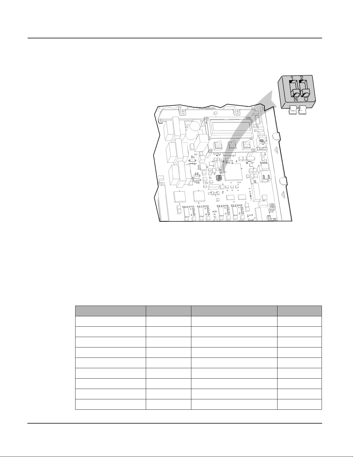
Configuration and Programming The configuration tool is used to set any of the programmable parameters of
the PowerLogic EM4800 Series meter. The combination of the configuration
tool and the state of the meter programming switches determine which
parameters can be set or changed. As shown in Figure 1, the programming
switches are two-position DIP switches labeled SW1, and are located inside
the meter cover below the Display button. To enable meter configuration,
both switches must be physically set to the ON (down) position (default).
© 2011 Schneider Electric All Rights Reserved
1
PowerLogic
"SW1"
PowerLogic configuration tool 01/2011
TM
EM4800 Series 930-112-01-B.00
Figure 1: Programming Switch location
Table 1 lists the programming capabilities associated with each parameter in
combination with the programming switches. After the meter has been
programmed, the programming switches can be turned OFF to prevent
tampering with metering parameters.
Parameter Read access Write access Activation time
Meter name Configuration tool Configuration tool Immediate
Badge number Configuration tool Configuration tool Immediate
Phone number Configuration tool Configuration tool Immediate
Alternate phone number Configuration tool Configuration tool Immediate
AT string Configuration tool Configuration tool Immediate
Host upload directory Configuration tool Configuration tool Immediate
Host download directory Configuration tool Configuration tool Immediate
Host IP address Configuration tool Configuration tool Immediate
PPP user name Configuration tool Configuration tool Immediate
Table 1: Programming access to meter parameters
© 2011 Schneider Electric All Rights Reserved2

930-112-01-B.00 PowerLogic
TM
EM4800 Series
01/2011 PowerLogic configuration tool
Parameter Read access Write access Activation time
PPP password Configuration tool Configuration tool Immediate
FTP user name Configuration tool Configuration tool Immediate
FTP password Configuration tool Configuration tool Immediate
Daily report interval start time Configuration tool Configuration tool Immediate
Daily report interval end time Configuration tool Configuration tool Immediate
Report period Configuration tool Configuration tool Immediate
Report interval in minutes Configuration tool Configuration tool Immediate
PT ratio Configuration tool Configuration tool + prog. switch ON Immediate
Default IP address Configuration tool Configuration tool Immediate
Default netmask Configuration tool Configuration tool Immediate
Default gateway Configuration tool Configuration tool Immediate
Reset dial readings No Access Configuration tool + prog. switch ON Immediate
Send PC time No Access Configuration tool Immediate
Programming switch state Configuration tool No Access Immediate
MAC address Configuration tool No Access Immediate
Report types Configuration tool Configuration tool Immediate
Manufacturing
Serial number Configuration tool No Access N/A
Part number Configuration tool No Access N/A
Model number Configuration tool Configuration tool + prog. switch ON After reset
Revision Configuration tool No Access
Firmware revision Configuration tool No Access N/A
Build number Configuration tool No Access
Meter and probe points
Name Configuration tool Configuration tool After reset
CT 1 current Configuration tool Configuration tool + prog. switch ON After reset
CT 2 current Configuration tool Configuration tool + prog. switch ON After reset
CT 3 current Configuration tool Configuration tool + prog. switch ON After reset
CT 1 phase Configuration tool Configuration tool + prog. switch ON After reset
CT 2 phase Configuration tool Configuration tool + prog. switch ON After reset
CT 3 phase Configuration tool Configuration tool + prog. switch ON After reset
© 2011 Schneider Electric All Rights Reserved
3

PowerLogic
PowerLogic configuration tool 01/2011
TM
EM4800 Series 930-112-01-B.00
Display Navigation The display on the front of the meter provides status information for each
circuit, and general information for metering. The PowerLogic EM4800 meter
has three buttons for navigating: a Display button, and left and right arrow
buttons. The display has a normal and a diagnostics mode.
Normal Mode
In Normal mode, the Display button scrolls through the information for each
meter. The left and right arrow buttons select the previous or next meter
points respectively. The following information is available:
• Real Energy Delivered kWh D
• Real Energy Received kWh R
• Real Power Watts
• Reactive Energy Delivered KVarhD
• Reactive Energy Received KVarhR
• Reactive Power Var
In Normal mode, the right and left arrow buttons scroll the display from meter
points 1 to 8, 1 to 12, or 1 to 24, depending on your configuration.
Diagnostics Mode
Diagnostics mode is accessed by pressing and holding the Display button for
5 seconds. In Diagnostics mode, pressing the Display button will scroll
through the following additional information:
• Send data command
• CT Primary value and Real Power Watts per phase
• Voltage per phase
• Local IP address
• Reset factory default IP address command
• Date and time (UTC)
In Diagnostics mode, the right and left arrow buttons scroll the display from
meter 1 through N. When the local IP address is shown on the LCD, use the
right and left arrow buttons to scroll through the following information:
• Remote host server IP address
• Time server IP address
• Default IP address
• Default NetMask
• Default gateway
• PPP user name
• Phone number
• AT command string
• Alternate phone number
• Unit serial number
• Firmware build number
• Ethernet port MAC address
• Firmware revision
• Potential transformer ratio
© 2011 Schneider Electric All Rights Reserved4
 Loading...