


Schneider Electric 865-V, 866-V, 885-V Installation Instructions

Installation Instructions
i2/b3 865/866/885-V Controller
30-3001-985 Rev G.4
Alternative Damper Shaft
Mounting Screw Position
Damper Shaft
Hex Mounting Screws
Alternative Damper Shaft
Mounting Screw Position 
Damper Shaft
Damper Shaft Collar
Cover Release
4-Position Dipswitch
|
|
|
|
Velocity Sensor |
P1 |
||
(LO) |
|||
Inputs |
P2 |
||
(Barbed fittings) |
|||
|
|
|
(HI) |
Two CPU LEDs |
|
|
|
|
|
||
Green = b3 controller |
|
|
|
Yellow = i2 controller |
|
|
|
Note: Input, Output, and Smart Sensor connections will vary per controller model.
Adjustable Stops |
Mounting Clip |
|
Actuator Clutch Release
(LOW) |
|
AIR FLOW |
866-V |
||||||||
|
|
|
|
|
|
|
|
|
|||
|
|
|
|
|
|
|
|
|
|||
|
|
|
|
|
INPUT |
|
|
|
|||
(HIGH) |
|
CAUTION |
|
|
|
||||||
|
|
|
|
||||||||
|
|
|
|
|
|
|
|
||||
|
|
|
|
|
MORE THAN ONE DISCONNECT SWITCH |
||||||
|
|
|
|
|
MAY BE REQUIRED TO DE-ENERGIZE THIS |
||||||
|
|
|
|
|
EQUIPMENT BEFORE SERVICING. |
|
|
|
|||
1 |
IN1 |
|
This equipment complies with part 15 of the FCC rules. |
||||||||
|
Operation is subject to the following two conditions. |
RS-485 |
|||||||||
|
|
|
|
|
(1) This device may not cause harmful interference. |
||||||
2 |
IN2 |
|
(2) This device must accept any interference received, |
PORT |
|||||||
|
including interference that may cause undesired |
||||||||||
|
|
|
|
|
operation. |
|
|
|
|||
3 |
RET |
|
UNIVERSAL |
|
|
|
|||||
|
|
|
|
|
|
|
|
||||
4 |
IN3 |
|
INPUTS |
ANALOG |
|||||||
|
|
|
|
|
|||||||
5 |
IN4 |
|
|
|
|
|
OUTPUTS |
||||
|
|
|
|
|
0-10 VDC |
|
|
||||
6 |
RET |
|
|
|
|
|
|
|
|||
|
|
|
|
|
|
|
|
||||
|
|
|
|
|
|
|
|
||||
7 |
SPWR |
|
SMART |
DIGITAL |
|||||||
|
|
|
|
|
|||||||
8 |
RET |
|
OUTPUTS |
||||||||
|
SENSOR |
||||||||||
|
|
|
|
|
24VAC , |
||||||
9 |
IN5 |
|
|
|
|
|
|||||
|
USE COPPER CONDUCTORS ONLY |
0.5A |
|||||||||
|
|||||||||||
10 24VAC |
|
|
|
|
|||||||
|
INPUT: CLASS 2 POWER ONLY |
|
|
|
|||||||
|
|
|
|
|
|
|
|
||||
11 |
|
|
|
|
24VAC , 0.42A, 10VA, 50/60HZ |
|
|
|
|||
|
|
|
|
|
|
||||||
|
|
|
|
|
|
|
|
|
|
|
|
COM  21
21
COM 20
SHIELD 19
A07 18
RET 17
AO6 16
TRIAC REF 15
OUT5 14
OUT4 13
OUT3 12
Mounting Bracket |
Cover Release |
|
Damper Position Indicator
Alternate
Mounting Bracket
Cover Release
Battery Location (Remove cover)
Service Port Location
(Remove cover)
Jumper for Actuator
Direction
TD LED = Yellow
RD LED = Green
Wireless LED = Red
Wiring Requirements: 300V
8A
22 - 12AWG
6 inch-lb screw tourque
i2/b3 865/866/885-V Controller Installation
To install the controller, follow these steps: |
2. |
The actuator is designed to mount over a 1/2” (12.7 mm) diameter |
|||
|
|
shaft with a minimum of 2.5” (63.5 mm) of exposed shaft. If the |
|||
|
|
damper shaft diameter is less than 1/ |
” (12.7 mm) an adapter is |
||
1. Check the mounting location for the Andover Continuum i2 or b3 |
|
2 |
|
|
|
|
required. An adapter (p/n AM-135) is available from Schneider |
||||
865/866/885-V controller. The unit is typically mounted with the |
|
Electric to allow mounting on 3/8” (9.5 mm) damper shaft. The |
|||
controller extending down or to the right from the damper shaft. |
|
865/866/885-V controller will not work with larger damper shaft |
|||
However, the controller can be operated in any position within |
|
diameters. |
|
|
|
the vertical plane. |
3. |
If the exposed damper shaft is less than 2” (51 mm) but at least 1” |
|||
Note: Installing the controller to the right (with the barbed |
|||||
|
(25.4 mm) long, move the two damper shaft mounting screws to the |
||||
fittings pointing down) helps prevent condensate from |
|
alternate lower damper shaft positions. |
|||
migrating into the on-board velocity sensor. |
4. |
Select the mounting bracket location that provides the most stability |
|||
With a downward extension, the available area around the damp- |
|||||
|
for the operation of the actuator. Position the mounting clip in the |
||||
er shaft must measure 6” (160 mm) down from the lower edge |
|
desired mounting bracket. Do not insert the clip more than half-way |
|||
of the shaft, 4.5” (120 mm) to the right, 1.5” (40 mm) to the left |
|
into the bracket. This allows the clip and the back of the actuator to |
|||
and 1.75” (45 mm) above the shaft. Ensure the location allows |
|
properly align with the VAV box. |
|
|
|
enough clearance for servicing. |
|
|
|
|
|
|
|
|
|
|
|
© 2018 Schneider Electric, all rights reserved.
i2/b3 865/866/885-V Controller Installation (continued)
5.Press and hold the green actuator clutch release and rotate the VAV damper shaft by hand to the fully closed position. Note whether the damper is rotated clockwise (CW) or counter-clock- wise (CCW) to close.
6.Slip the controller over the damper shaft. Position the actuator and, using a self tapping sheet metal screw, secure the mounting clip to the VAV box.
7.Next, press the actuator toward the box until the actuator comes into contact with the VAV box, the mounting clip snaps into the bracket, or the back of the actuator comes into contact with the VAV box.
8.Press and hold the green actuator clutch release (see Figure on cover page) and rotate the actuator collar to a nearly closed position, the 5° index mark, if the damper shaft was rotated counter-clockwise to close (Step 5). Rotate the actuator collar to the 85° index mark if the damper shaft was rotated clockwise to close (Step 5).
9.Tighten the two damper hex mounting screws using a 1/8” hex Allen wrench. The minimum torque required to secure the controller to the damper shaft depends on the shaft material. The maximum torque for the socket screws is 30 inch-pounds (3.4 Nm).
Note: The damper should rotate freely when the clutch is released. If it does not, the actuator may not be properly aligned with the damper shaft – it may be necessary to repeat Steps 4 through 9 using a new orientation.
10.If the damper does not provide a mechanical stop in the open direction, or it is not desirable to use the damper’s open stop, set the adjustable stops on the 865/866/885-V controller to the desired position. Use a 1/4” hex driver to adjust the screw stop on the controller.
Note: For the 866-V model only, you must calibrate the damper position feedback reporting option before using. You calibrate damper position feedback reporting by changing the damper’s output attribute, LCDState, from DISABLED to ENABLED. The attribute, OverrideValue, indicates the damper position as a fractional value from 0 (at the closed stop) to 1 (at the open stop).
Whenever the Actuator Clutch Release button is pressed and the Actuator is moved manually, you need to recalibrate damper position feedback reporting. During damper calibration, the damper output will rotate from one endstop to the other and then return to its original position. It is also recommended that you periodically recalibrate damper position feedback reporting using a Plain English (PE) program.
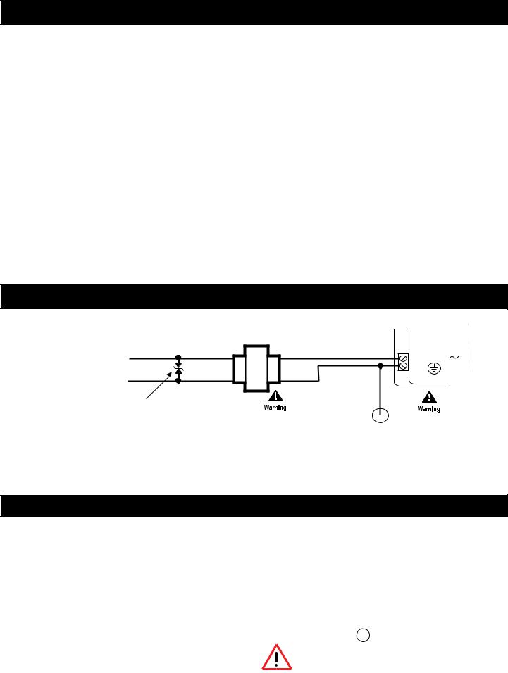
AC Power Connection
|
24 VAC Step-Down |
|
or Isolation Transformer |
|
X1 |
AC Line |
10 24VAC |
11 |
|
Power |
|
|
X2 |
Optional Varistor |
|
|
|
|
|
|
|
|
(Choose a voltage rating appropriate |
Each controller on the network must have its own |
|
|
|
|
|
|
|
to the input voltage applied. |
|
|
|
|
|
|
Class 2 power only! |
|
|
|
|
|
|
|
|||
For example, 130V or 250V) |
24V Step-Down or Isolation Transformer. Be sure to |
|
||||||
|
wire the secondary of the 24V Step-Down Transformer |
|
||||||
|
exactly as shown. Pin 11 must be connected to the grounded |
|
||||||
|
side of the secondary on all transformers used in the system. |
|
||||||
|
Otherwise, damage to one or more controllers may result. |
|
||||||
Note: Use care when attaching power wiring to these connectors. They are not to be used as a strain relief. The connectors cannot withstand excessive bending or flexing.
Failing to install this transformer on remote controllers can damage it and other controllers on the network.
Wiring Rules
These modules are intended for installation within the enclosure of another product.
Do not remotely ground any part of the input sensor wiring.
•When stripping wire, be careful not to drop small pieces of wire inside the cabinet.
•Don’t run your input wiring in the same conduit with AC power.
•Don’t run your input wiring in the same conduit with your output wiring.
Remote grounds connected to the return terminal could make the system operate incorrectly or damage the equipment.
The signal return is not true earth ground. It is an electronic reference point necessary to interpret the sensor properly.
For reliable input operation, follow these input wiring guidelines:
•Never lay wires across the surface of a printed circuit board.
•Wires should never be within 1” or 25 mm of any component on a printed circuit board.
•Use shielded input wire.
•Terminate the shield of the input wires at one end of the run only — preferably at the end where your I/O module is located.
Grounding the Controller
To insure proper operation of the controller, it must be connected to a good earth ground.The connection must be made as close to the module as possible.
Caution: Earth ground (  ) must be connected to avoid module damage.
Removing the Plastic Battery Tab
Before operating the controller, open the cover and remove the protective plastic battery tab. The battery location is shown in the illlustration on the cover page.
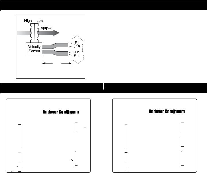
Connecting the Air Velocity Sensor |
|
|
|
1. Connect the low pressure side of the velocity sensor to the barbed |
|
|
fitting labeled P1 (LO) on the controller. |
|
|
2. Connect the high pressure side of the velocity sensor to the fitting |
|
|
labeled P2 (HI) on the controller. |
|
|
Notes: Use a recommended maximum length of 4’ (1.2 m) FRPE |
|
|
plyetheylene tubing or 0.25” (6.34 mm) O.D. and 0.125” |
|
|
(3.175 mm) I.D. Tygon tubing. |
|
|
Do not expose the velocity sensor to moisture. If moisture |
|
4’ |
condensation is a potential problem, orient the tubing and |
|
controller so that the barbed fittings are above the lowest |
||
(1.2 m) |
||
part of the tubing to create a moisture trap. |
||
Tubing (Max.) |
||
|
||
Connections for i2/b3 865-V Controller |
Connections for i2/b3 866-V Controller |
(LOW) |
|
INPUT |
865-V |
|
|
AIR FLOW |
|
(HIGH) |
|
|
|
|
|
1IN 1
2IN 2
3RET
4IN 3
5IN 4
6RET
7SPWR
8RET
9IN 5
1024VAC
11
CAUTION
MORE THAN ONE DISCONNECT SWITCH MAY BE REQUIRED
TO DE-ENERGIZE THIS EQUIPMENT BEFORE SERVICING.
UNIVERSAL INPUTS
This equipment complies with part 15 of the FCC rules. Operation is subject to the following two conditions.
(1) This device may not cause harmful interference.
(2) This device must accept any interference received, including interference that may cause undesired operation.
SMART
SENSOR
USE COPPER CONDUCTORS ONLY


 INPUT: CLASS 2 POWER ONLY
24VAC
 , 0.42A, 10VA, 50/60HZ
COM  18
18
RS-485 COM 17 PORT
SHIELD 16
|
TRIAC REF |
15 |
|
DIGITAL |
OUT5 |
14 |
|
OUTPUTS |
|||
|
|
||
24VAC , |
OUT4 |
13 |
|
0.5A |
OUT3 |
12 |
|
|
(LOW) |
|
INPUT |
866-V |
|
|
AIR FLOW |
|
(HIGH) |
|
|
|
|
|
1IN 1
2IN 2
3RET
4IN 3
5IN 4
6RET
7SPWR
8RET
9IN 5
1024VAC
11
CAUTION
MORE THAN ONE DISCONNECT |
|
|
SWITCH MAY BE REQUIRED |
RS-485 |
|
TO DE-ENERGIZE THIS EQUIPMENT |
PORT |
|
BEFORE SERVICING. |
||
|
UNIVERSAL
INPUTS
This equipment complies with part 15 of the FCC rules. Operation is subject to the following two conditions.
(1) This device may not cause harmful interference.
(2) This device must accept any interference received, including interference that may cause undesired operation.
SMART
SENSOR
USE COPPER CONDUCTORS ONLY

 INPUT: CLASS 2 POWER ONLY
24VAC , 0.42A, 10VA, 50/60HZ
ANALOG
OUTPUTS 0-10 VDC 

DIGITAL OUTPUTS 24VAC , 0.5A
COM  21
21
COM  20
20
SHIELD 19
A07 18
RET 17
AO6 16
TRIAC REF 15
OUT5 14
OUT4 13
OUT3 12
Airflow Input |
Airflow Input |
One Low and one High connection |
One Low and one High connection |
Universal Inputs |
Universal Inputs |
Four input and two return connections — terminals 1-6 |
Four input and two return connections — terminals 1-6 |
Smart Sensor Bus Interface |
Smart Sensor Bus Interface |
One Smart Sensor connection — terminals 7-9 |
One Smart Sensor connection — terminals 7-9 |
Power Connection |
Power Connection |
One 24 VAC connection and ground — terminals 10-11 |
One 24 VAC connection and ground — terminals 10-11 |
Digital Outputs |
Digital Outputs |
Three output connections and one triac reference — terminals 12-15 |
Three output connections and one triac reference — terminals 12-15 |
RS-485 Port |
Analog Outputs |
One port for a BACnet MS/TP or Infinet connection — terminals 16-18 |
Two analog outputs and one return connection — terminals 16-18 |
|
RS-485 Port |
|
One port for a BACnet MS/TP or Infinet connection — terminals 19-21 |
 Loading...