


Schneider Electric ACRC501, ACRC500, ACRC502 User Manual

Operation and Maintenance Manual
InRow® Chilled Water Cooling Units
InRow® RC
ACRC500, ACRC501, ACRC502
990-3237B-001
Publication Date: November 2014

Schneider Electric IT Corporation Legal Disclaimer
The information presented in this manual is not warranted by the Schneider Electric IT Corporation to be
authoritative, error free, or complete. This publication is not meant to be a substitute for a detailed operational
and site specific development plan. Therefore, Schneider Electric IT Corporation assumes no liability for
damages, violations of codes, improper installation, system failures, or any other problems that could arise
based on the use of this Publication.
The information contained in this Publication is provided as is and has been prepared solely for the purpose of
evaluating data center design and construction. This Publication has been compiled in good faith by Schneider
Electric IT Corporation. However, no representation is made or warranty given, either express or implied, as to
the completeness or accuracy of the information this Publication contains.
IN NO EVENT SHALL SCHNEIDER ELECTRIC IT CORPORATION, OR ANY PARENT, AFFILIATE OR
SUBSIDIARY COMPANY OF SCHNEIDER ELECTRIC IT CORPORATION OR THEIR RESPECTIVE
OFFICERS, DIRECTORS, OR EMPLOYEES BE LIABLE FOR ANY DIRECT, INDIRECT, CONSEQUENTIAL,
PUNITIVE, SPECIAL, OR INCIDENTAL DAMAGES (INCLUDING, WITHOUT LIMITATION, DAMAGES FOR
LOSS OF BUSINESS, CONTRACT, REVENUE, DATA, INFORMATION, OR BUSINESS INTERRUPTION)
RESULTING FROM, ARISING OUT, OR IN CONNECTION WITH THE USE OF, OR INABILITY TO USE THIS
PUBLICATION OR THE CONTENT, EVEN IF SCHNEIDER ELECTRIC IT CORPORATION HAS BEEN
EXPRESSLY ADVISED OF THE POSSIBILITY OF SUCH DAMAGES. SCHNEIDER ELECTRIC IT
CORPORATION RESERVES THE RIGHT TO MAKE CHANGES OR UPDATES WITH RESPECT TO OR IN
THE CONTENT OF THE PUBLICATION OR THE FORMAT THEREOF AT ANY TIME WITHOUT NOTICE.
Copyright, intellectual, and all other proprietary rights in the content (including but not limited to software, audio,
video, text, and photographs) rests with Schneider Electric It Corporation or its licensors. All rights in the
content not expressly granted herein are reserved. No rights of any kind are licensed or assigned or shall
otherwise pass to persons accessing this information.
This Publication shall not be for resale in whole or in part.

Table of Contents
General Information...........................................................1
Important Safety Information . . . . . . . . . . . . . . . . . . . . . . . . . . . . . . . . . 1
Safety Notices During Operation . . . . . . . . . . . . . . . . . . . . . . . . . . . . . . 2
Commissioning ..................................................................4
Checklists . . . . . . . . . . . . . . . . . . . . . . . . . . . . . . . . . . . . . . . . . . . . . . . . 4
Initial inspection checklist . . . . . . . . . . . . . . . . . . . . . . . . . . . . . 4
Electrical inspection checklist . . . . . . . . . . . . . . . . . . . . . . . . . . 5
Mechanical inspection checklist . . . . . . . . . . . . . . . . . . . . . . . . 6
User interface inspection checklist . . . . . . . . . . . . . . . . . . . . . . 7
Start-up inspection checklist . . . . . . . . . . . . . . . . . . . . . . . . . . . 7
Final inspection checklist . . . . . . . . . . . . . . . . . . . . . . . . . . . . . 7
Operation...........................................................................8
Display Interface. . . . . . . . . . . . . . . . . . . . . . . . . . . . . . . . . . . . . . . . . . . 8
Using the Display . . . . . . . . . . . . . . . . . . . . . . . . . . . . . . . . . . . . . . . . . . 9
Scrolling status screens . . . . . . . . . . . . . . . . . . . . . . . . . . . . . . 9
Main menu screens . . . . . . . . . . . . . . . . . . . . . . . . . . . . . . . . . . 9
Navigating the main menu . . . . . . . . . . . . . . . . . . . . . . . . . . . . 9
Navigating sub-menus . . . . . . . . . . . . . . . . . . . . . . . . . . . . . . 10
Using the Path statement . . . . . . . . . . . . . . . . . . . . . . . . . . . . 10
Password entry . . . . . . . . . . . . . . . . . . . . . . . . . . . . . . . . . . . . 11
Start the cooling unit . . . . . . . . . . . . . . . . . . . . . . . . . . . . . . . . 11
Stop the cooling unit . . . . . . . . . . . . . . . . . . . . . . . . . . . . . . . . 12
General Configuration . . . . . . . . . . . . . . . . . . . . . . . . . . . . . . . . . . . . . 13
Cooling unit configuration . . . . . . . . . . . . . . . . . . . . . . . . . . . . 13
Contacts . . . . . . . . . . . . . . . . . . . . . . . . . . . . . . . . . . . . . . . . . . . . . . . . 14
View the state of input and output contacts . . . . . . . . . . . . . . 14
Edit the normal state of input and output contacts . . . . . . . . . 14
Cooling Group Configuration . . . . . . . . . . . . . . . . . . . . . . . . . . . . . . . . 15
Configure the cooling group . . . . . . . . . . . . . . . . . . . . . . . . . . 15
Identify the cooling unit . . . . . . . . . . . . . . . . . . . . . . . . . . . . . . 16
Configure Modbus . . . . . . . . . . . . . . . . . . . . . . . . . . . . . . . . . . 16
InRow RC Operation and Maintenance Manual i

Control the Environment . . . . . . . . . . . . . . . . . . . . . . . . . . . . . . . . . . . 17
How the Cool mode works . . . . . . . . . . . . . . . . . . . . . . . . . . . 17
Setpoints . . . . . . . . . . . . . . . . . . . . . . . . . . . . . . . . . . . . . . . . . 17
PID settings . . . . . . . . . . . . . . . . . . . . . . . . . . . . . . . . . . . . . . . 18
Tune the PID loop . . . . . . . . . . . . . . . . . . . . . . . . . . . . . . . . . . 19
Run hours . . . . . . . . . . . . . . . . . . . . . . . . . . . . . . . . . . . . . . . . 20
Thresholds . . . . . . . . . . . . . . . . . . . . . . . . . . . . . . . . . . . . . . . . 20
Service intervals . . . . . . . . . . . . . . . . . . . . . . . . . . . . . . . . . . . 20
Display Settings . . . . . . . . . . . . . . . . . . . . . . . . . . . . . . . . . . . . . . . . . . 21
Password & timeout . . . . . . . . . . . . . . . . . . . . . . . . . . . . . . . . 21
Date & time . . . . . . . . . . . . . . . . . . . . . . . . . . . . . . . . . . . . . . . 21
Adjust display . . . . . . . . . . . . . . . . . . . . . . . . . . . . . . . . . . . . . 21
Display units . . . . . . . . . . . . . . . . . . . . . . . . . . . . . . . . . . . . . . 22
Network Configuration . . . . . . . . . . . . . . . . . . . . . . . . . . . . . . . . . . . . . 23
Configure the network . . . . . . . . . . . . . . . . . . . . . . . . . . . . . . . 23
View Status Readings . . . . . . . . . . . . . . . . . . . . . . . . . . . . . . . . . . . . . 24
Scrolling status screens . . . . . . . . . . . . . . . . . . . . . . . . . . . . . 24
Cooling unit status . . . . . . . . . . . . . . . . . . . . . . . . . . . . . . . . . . 24
Cooling group status . . . . . . . . . . . . . . . . . . . . . . . . . . . . . . . . 25
About the cooling unit . . . . . . . . . . . . . . . . . . . . . . . . . . . . . . . 25
Event Log. . . . . . . . . . . . . . . . . . . . . . . . . . . . . . . . . . . . . . . . . . . . . . . 26
View event log . . . . . . . . . . . . . . . . . . . . . . . . . . . . . . . . . . . . . 26
Clear event log . . . . . . . . . . . . . . . . . . . . . . . . . . . . . . . . . . . . 26
Respond to Alarms . . . . . . . . . . . . . . . . . . . . . . . . . . . . . . . . . . . . . . . 27
View active alarms . . . . . . . . . . . . . . . . . . . . . . . . . . . . . . . . . 27
Clear active alarms . . . . . . . . . . . . . . . . . . . . . . . . . . . . . . . . . 27
Alarm messages and suggested actions . . . . . . . . . . . . . . . . . 27
Network Management Card .............................................30
Quick Configuration . . . . . . . . . . . . . . . . . . . . . . . . . . . . . . . . . . . . . . . 30
Overview . . . . . . . . . . . . . . . . . . . . . . . . . . . . . . . . . . . . . . . . . 30
TCP/IP configuration methods . . . . . . . . . . . . . . . . . . . . . . . . 30
Schneider Electric Device IP Configuration Wizard . . . . . . . . 30
.ini file utility . . . . . . . . . . . . . . . . . . . . . . . . . . . . . . . . . . . . . . . 31
BOOTP & DHCP configuration . . . . . . . . . . . . . . . . . . . . . . . . 32
Local access to the control console . . . . . . . . . . . . . . . . . . . . 33
Remote access to the control console . . . . . . . . . . . . . . . . . . 33
Control console . . . . . . . . . . . . . . . . . . . . . . . . . . . . . . . . . . . . 34
ii
InRow RC Operation and Maintenance Manual

Access a Configured Network Management Card . . . . . . . . . . . . . . . . 35
Overview . . . . . . . . . . . . . . . . . . . . . . . . . . . . . . . . . . . . . . . . . 35
Web interface . . . . . . . . . . . . . . . . . . . . . . . . . . . . . . . . . . . . . 35
Telnet and SSH . . . . . . . . . . . . . . . . . . . . . . . . . . . . . . . . . . . . 35
Simple Network Management Protocol (SNMP) . . . . . . . . . . . 36
FTP/SCP . . . . . . . . . . . . . . . . . . . . . . . . . . . . . . . . . . . . . . . . . 36
Modbus . . . . . . . . . . . . . . . . . . . . . . . . . . . . . . . . . . . . . . . . . . 36
Recover From a Lost Password . . . . . . . . . . . . . . . . . . . . . . . . . . . . . . 38
Maintenance ....................................................................39
Monthly Preventive Maintenance . . . . . . . . . . . . . . . . . . . . . . . . . . . . . 39
Environment . . . . . . . . . . . . . . . . . . . . . . . . . . . . . . . . . . . . . . 39
Cleanliness . . . . . . . . . . . . . . . . . . . . . . . . . . . . . . . . . . . . . . . 39
Mechanical . . . . . . . . . . . . . . . . . . . . . . . . . . . . . . . . . . . . . . . 40
Electrical . . . . . . . . . . . . . . . . . . . . . . . . . . . . . . . . . . . . . . . . . 40
Quarterly Preventive Maintenance . . . . . . . . . . . . . . . . . . . . . . . . . . . . 41
Mechanical . . . . . . . . . . . . . . . . . . . . . . . . . . . . . . . . . . . . . . . 41
Functional . . . . . . . . . . . . . . . . . . . . . . . . . . . . . . . . . . . . . . . . 41
Semi-Annual Preventive Maintenance . . . . . . . . . . . . . . . . . . . . . . . . . 41
Cleanliness . . . . . . . . . . . . . . . . . . . . . . . . . . . . . . . . . . . . . . . 41
Troubleshooting...............................................................42
iiiInRow RC Operation and Maintenance Manual


General Information
Important Safety Information
Read the instructions carefully to become familiar with the equipment before trying to install, operate, service,
or maintain it. The following special messages may appear throughout this manual or on the equipment to warn
of potential hazards or to call attention to information that clarifies or simplifies a procedure.
The addition of this symbol to a Danger or Warning safety label indicates that an electrical hazard
exists which will result in personal injury if the instructions are not followed.
This is the safety alert symbol. It is used to alert you to potential personal injury hazards. Obey all
safety messages that follow this symbol to avoid possible injury or death.
DANGER
DANGER indicates an imminently hazardous situation which, if not avoided, will result in death
or serious injury.
WARNING
WARNING indicates a potentially hazardous situation which, if not avoided, can result in death
or serious injury.
CAUTION
CAUTION indicates a potentially hazardous situation which, if not avoided, can result in minor
or moderate injury.
NOTICE
NOTICE addresses practices not related to physical injury including certain environmental
hazards, potential damage or loss of data.
1InRow RC Operation and Maintenance Manual

Safety Notices During Operation
Read and adhere to the following important safety considerations when working with this equipment. Follow all
local and national regulations when handling refrigerants. Service to the components in the refrigeration loop
should be performed only by a certified HVAC technician.
DANGER
HAZARD OF ELECTRIC SHOCK, EXPLOSION, OR ARC FLASH
• Apply appropriate personal protective equipment (PPE) and follow safe electrical work
practices. See NFPA 70E or CSA Z462.
• This equipment must be installed and serviced by qualified personnel only.
• Turn off all power supplying this equipment before working on or inside the equipment.
• Always use a properly rated voltage sensing device to confirm power is off.
• Replace all devices, doors, and covers before turning on power to this equipment.
Failure to follow these instructions will result in death or serious injury.
WARNING
HAZARD FROM MOVING PARTS
Keep hands, clothing, and jewelry away from moving parts. Check the equipment for
foreign objects before closing the doors and starting the equipment.
Failure to follow these instructions can result in death, serious injury, or
equipment damage.
WARNING
HAZARD TO EQUIPMENT OR PERSONNEL
All work must be performed by Schneider Electric qualified personnel.
Failure to follow these instructions can result in death, serious injury, or
equipment damage.
CAUTION
HAZARD TO EQUIPMENT OR PERSONNEL
Ensure that all spare parts and tools are removed from the equipment before operating it
Failure to follow these instructions can result in injury or equipment damage.
InRow RC Operation and Maintenance Manual2

NOTICE
STATIC ELECTRICITY HAZARD
Circuit boards contained within this unit are sensitive to static electricity. Use one or more
electrostatic-discharge device while handling the boards.
Failure to follow these instructions can result in equipment damage.
3InRow RC Operation and Maintenance Manual
Commissioning
After installation, complete the following checklists to verify that all components are working properly and that
the equipment is ready to begin operation.
Checklists
Initial inspection checklist
The initial inspection ensures that the equipment has been properly installed, the location of the cooling unit has
been properly prepared and the cooling unit is free of damage.
WARNING
DAMAGE TO EQUIPMENT OR PERSONNEL
Do not run service utilities in front of the fan outlet.
Failure to follow these instructions can result in death, serious injury, or
equipment damage.
NOTE: The vapor barrier minimizes moisture infiltration. Without a vapor barrier, it will be difficult to maintain
the humidity in the room. Do not introduce unconditioned outside air into the space.
Ensure that:
The installation procedure is complete according to the requirements of this installation manual.
The walls, floor, and ceiling of the room where the cooling unit is located are sealed with a vapor barrier.
There is no evidence of damage to the cooling unit.
The clearance around the equipment is in accordance with local and national codes and regulations as well
as this installation manual.
The cooling unit is level and joined to the adjacent racks
The cooling unit is not installed at the open end of a row.
InRow RC Operation and Maintenance Manual4

Electrical inspection checklist
The electrical inspection verifies that all electrical connections are secure and correct and that the equipment is
properly grounded.
WARNING
ELECTRICAL HAZARD
• Electrical service must conform to local and national electrical codes and regulations.
• The equipment must be grounded.
Failure to follow these instructions can result in death, serious injury, or
equipment damage.
Ensure that:
Incoming voltages match the phase and voltage listing on the nameplate.
Electrical wiring complies with local and national codes and regulations.
Equipment is properly grounded.
Front door is properly grounded.
Electrical connections are tight, including contactors, terminal blocks, controllers, switches, relays, auxiliary
devices, and field connections.
Circuit breakers are properly connected and securely attached to the DIN rail.
5InRow RC Operation and Maintenance Manual

Mechanical inspection checklist
The mechanical inspection verifies that all mechanical components and connections are secure.
CAUTION
PIPING INSTALLATION
Failure to properly install piping may result in improper cooling unit operation or possible
damage to the cooling unit or surrounding equipment.
Failure to follow these instructions can result in equipment damage.
Ensure that:
Condensate drain line is at least the size of the drain connection.
Mechanical connections are tight.
Fans are turning freely and the blades are not distorted or bent.
Pipe fittings are tight.
Air is bled from the water system. If air remains in the system, bleed it out now.
Supply chilled water temperature is recorded.
Chilled water flow is correct based on the performance requirements of the cooling unit.
Field-installed traps and piping are in accordance with the installation manual. Strainers are in place in the
chilled water supply loop. Proper piping practices have been followed.
Piping is adequately supported and isolated when necessary.
Field-installed service valves are open.
Water outlet temperature sensor is positioned correctly. For top-connected cooling units, the wire with only a
green wire tie is positioned in connector J23. For bottom-connected cooling units, the wire with both green
and white wire ties is positioned in connector J23.
Piping in the building and on the roof is properly insulated.
Covers and guards are in place.
InRow RC Operation and Maintenance Manual6

User interface inspection checklist
The user interface inspection verifies that the sensors and internal communication links are installed properly.
Check that the outdoor heat exchanger is connected to the cooling unit and to the other cooling units in the
room if you are using cooling group controls.
Ensure that:
An A-Link bus is connected to each cooling unit and a terminator is plugged into all unused A-Link
connectors.
The input contacts and output relays are connected correctly.
The building management system is connected correctly and a terminator is wired into the final cooling unit.
The temperature sensors located on the front of the equipment are connected correctly.
The rack temperature sensors are installed correctly.
The network port is connected correctly and an IP address has been assigned to the cooling unit.
The optional rope water detection device is installed properly.
Start-up inspection checklist
The start-up inspection ensures that the equipment is operating properly after the initial start-up. This inspection
verifies that all modes of operation are working correctly and that the cooling unit is ready for normal operation.
While the equipment is operating, ensure that:
The cooling unit is free from malfunctions, including chilled water leaks, unusual vibrations, or other
irregularities, in each mode of operation.
The current draw of fan motors and transformers for the cooling operation is within the ratings of the
respective circuit breakers.
Record the current at the main power connection of the main circuit breaker.
Record all current draws on the load side of any circuit breakers used for each device.
Compare the circuit breaker setting for each device to the actual current measured and the full load amps of
the device to verify that the current draws are acceptable.
Feed B can supply power to all functions in the equipment.
The cool cycle engages.
The correct water outlet temperature sensor is positioned in connector J23.
Air filters are clean and free of debris. Replace air filters as needed.
The clogged filter alarm is operating properly.
Cover 1/3 of the filter area to initiate the alarm.
Final inspection checklist
The final inspection verifies that the system is clean, and the start-up form has been sent to Schneider Electric.
Ensure that:
The system is clean and free from debris.
Packaging materials are disposed of properly.
The start-up form was completed and sent to Schneider Electric.
7InRow RC Operation and Maintenance Manual

Operation
Display Interface
Status
Check
Log
Warning
Critical
ESC
?
na1958a
Item Description Function
Critical Alarm LED (red) When lit, a critical alarm condition exists and requires your
immediate attention.
Warning Alarm LED (yellow) When lit, a warning alarm condition exists. Failure to correct this
condition could cause a critical alarm.
Check Log LED (yellow) When lit, at least one new event has been logged since the last time
the log was checked. Only events that pertain to the operation of the
cooling unit will activate the LED.
Status LED (green) When lit, the cooling unit is receiving electrical power. When flashing
green, the cooling unit is downloading firmware for the controller.
This takes several minutes.
Liquid Crystal Display (LCD) View alarms, status data, context-sensitive help, and modify
configurable items.
UP and DOWN arrow keys Select menu items and access information.
ESC key Return to previous screen or cancel current operation.
ENTER key Open menu items and input changes to cooling group level and
cooling unit level settings.
HELP key Display context-sensitive help. Press the HELP key for information
about each option on the screen and for instructions on performing
tasks.
InRow RC Operation and Maintenance Manual8

Using the Display
Every time you apply power to the cooling unit, the display interface initializes, causing the LEDs to cycle and
the alarm-tone to activate.
Scrolling status screens
After start-up, the interface displays the firmware revision number of the display interface. The display interface
then scrolls automatically and continuously through screens of status information. Press the up or down arrow
key to interrupt the automatic scrolling and view a specific status screen. To return to the scrolling status
screens, press ESC from one of the main menu screens.
Status Screen Name Status Information Displayed
InRow RC • On/Standby
• Unit identifier
• Cooling Unit name
• Cooling Unit location
Group • Alarms/No Alarms
• Cool Outpt (Cool Output) kW
• Cool Setpt (Cool Setpoint) °C (or °F)
• Max Rack (Maximum Rack Temperature) °C (or °F)
Unit • Alarms/No Alarms
• Cool Output kW
• Max Rack In (Maximum Rack Inlet Temperature) °C (or °F)
• Air Flow l/s (liters per second) or CFM (cubic feet per minute)
Main menu screens
On any top-level status screen, press the ENTER or ESC key to open the first
main menu screen.
NOTE: Once a period of inactivity (at the keys of the display interface)
exceeds the Password Timeout setting, the display interface returns to
the scrolling status screens.
For information on setting the time-out duration, see
“Password & timeout” on page 21.
All main menu choices are displayed on a series of six main menu screens.
Navigating the main menu
Selector arrow: Press the up or down arrow key to move the selector arrow
to a main menu option. Press the ENTER key to view the selected sub-menu
screen. In the example shown below, the selector arrow points to the Set Date
and Time setting. To select that item, press the ENTER key.
Time: 13:15:23
Date: 18-Nov-2010
Format: dd/mm/yyyy
na5271a
NOTE: If the selector arrow is on the top line of a main menu screen, press the
up arrow key to move the selector arrow to the top line of the previous screen.
On/Standby
View Alarms
Clear Alarms
View Event Log
Clear Event Log
Configure Modbus
Set Date & Time
Set Password
Set Display Units
Configure Display
Configure Network
About InRow RC
Set Identification
Service Intervals
View Run Hours
Configure Unit
Configure Group
Set Group PIDs
View Group Status
View Unit Status
Set Group Setpoints
Set Unit Threshlds
na5388a
9InRow RC Operation and Maintenance Manual
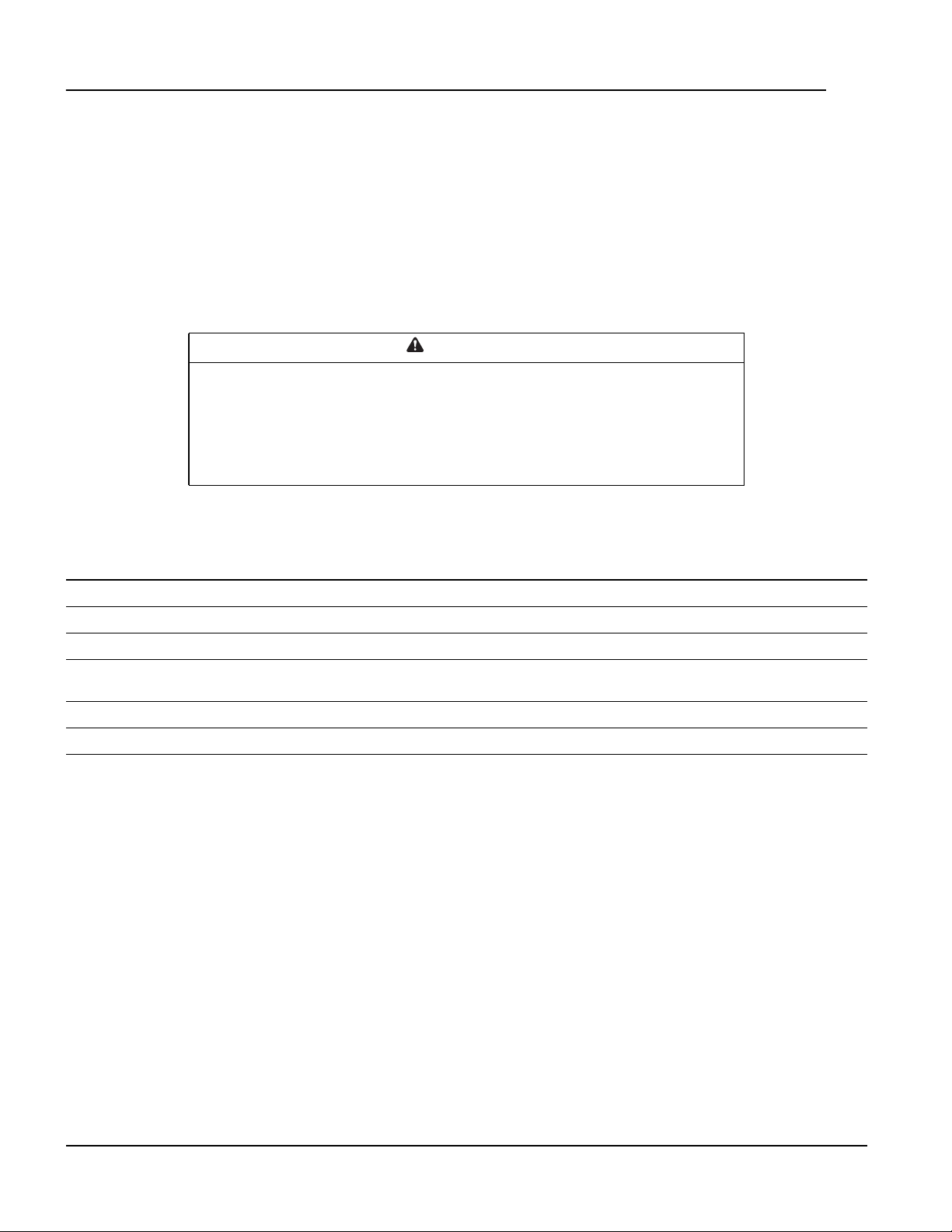
Continue arrows: Continue arrows indicate that additional options or settings are available on a menu or
status screen. Press the up or down arrow key to view the additional items.
Clear Event Log
Configure Modbus
Set Date & Time
Set Password
na1623f
Navigating sub-menus
Selecting a option displays the sub-menu screen for that option. In this example, the selector arrow is on the
top line of the Set Date and Time sub-menu screen.
Time: 13:15:23
Date: 18-Nov-2010
Format: dd/mm/yyyy
na1623g
Use the up or down arrow key to move the selector arrow to an option, and press the ENTER key.
• List of choices: If the setting is a list of choices, an input arrow displays next to the setting. Press the
up or down arrow key to select the menu option to change. Then press the ENTER key to exit the input
mode and save the setting. Press the ESC key to exit without saving.
• Numbers or text fields: If the setting is a number or text field, use the arrow keys to select the value of
the first character, and press the ENTER key to move to the next character. Press the ENTER key after
the last character is set to exit the input mode and save the setting. Press the ESC key to exit without
saving. If an invalid value is entered, the display interface beeps and restores the previous valid value to
the field.
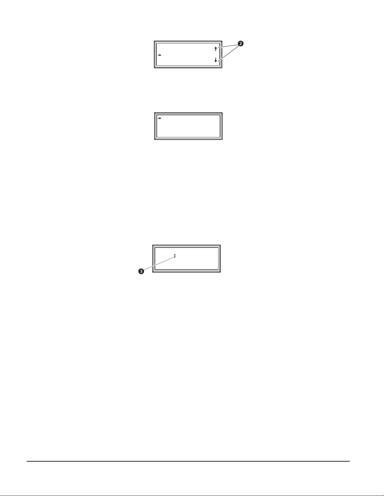
Input arrows: Input arrows next to a selected setting indicate that the setting can be modified by pressing
the up or down arrow key. Press the ENTER key to save the change or the ESC key to cancel the change.
Time: 13:15:23
Date: 18-Nov-2010
Format: dd/mm/yyyy
na1622aa
Using the Path statement
Select the main- and sub-menu options specified in the path statement to view or configure a setting. The path
statement lists the main- and sub-menu items you select to navigate to the item to view or modify. The parts of
the path statement are defined below:
Path: Main > Set Password > Change Passwords
Main >: Your starting point is the main menu.
Set Password >: Scroll to and select this option from the main menu.
Change Passwords >: Scroll to and select this option from the sub-menu.
Subsequent options are listed and defined under the path statement.
InRow RC Operation and Maintenance Manual10
 Loading...