


 Loading...
ILA1B, ILA1F, ILA1R
Lexium Integrated Drive Product manual
V2.00, 09.2008
0198441113562, V2.00, 09.2008

Important information |
ILA1B, ILA1F, ILA1R |
Important information
This manual is part of the product.
Carefully read this manual and observe all instructions.
Keep this manual for future reference.
Hand this manual and all other pertinent product documentation over to all users of the product.
Carefully read and observe all safety instructions and the chapter "Before you begin - safety information".
Some products are not available in all countries.
For information on the availability of products, please consult the catalog.
Subject to technical modifications without notice.
All details provided are technical data which do not constitute warranted qualities.
Most of the product designations are registered trademarks of their respective owners, even if this is not explicitly indicated.
0198441113562, V2.00, 09.2008
2 |
Lexium Integrated Drive |

ILA1B, ILA1F, ILA1R |
Table of Contents |
0198441113562, V2.00, 09.2008
Table of Contents
Important information. . . . . . . . . . . . . . . . . . . . . . . . . . . . . . . . . 2 Table of Contents . . . . . . . . . . . . . . . . . . . . . . . . . . . . . . . . . . . . 3 Writing conventions and symbols. . . . . . . . . . . . . . . . . . . . . . . 9 1 Introduction . . . . . . . . . . . . . . . . . . . . . . . . . . . . . . . . . . . . . . . . 11
1.1 About this manual . . . . . . . . . . . . . . . . . . . . . . . . . . . . . 11
1.2 Unit overview. . . . . . . . . . . . . . . . . . . . . . . . . . . . . . . . . 11
1.3 Components and interfaces . . . . . . . . . . . . . . . . . . . . . 12 1.3.1 Components . . . . . . . . . . . . . . . . . . . . . . . . . . . . . . . 13 1.3.2 Interfaces . . . . . . . . . . . . . . . . . . . . . . . . . . . . . . . . . 14
1.4 Name plate . . . . . . . . . . . . . . . . . . . . . . . . . . . . . . . . . . 15
1.5 Type code . . . . . . . . . . . . . . . . . . . . . . . . . . . . . . . . . . . 16
1.6 Documentation and literature references . . . . . . . . . . . 17
1.7 Declaration of conformity. . . . . . . . . . . . . . . . . . . . . . . . 18
1.8 TÜV certificate for functional safety. . . . . . . . . . . . . . . . 19
2 Before you begin - safety information. . . . . . . . . . . . . . . . . . . 21
2.1 Qualification of personnel . . . . . . . . . . . . . . . . . . . . . . . 21 2.2 Intended use . . . . . . . . . . . . . . . . . . . . . . . . . . . . . . . . . 21 2.3 Hazard categories . . . . . . . . . . . . . . . . . . . . . . . . . . . . . 22 2.4 Basic information. . . . . . . . . . . . . . . . . . . . . . . . . . . . . . 23 2.5 Functional safety . . . . . . . . . . . . . . . . . . . . . . . . . . . . . . 24 2.6 Standards and terminology . . . . . . . . . . . . . . . . . . . . . . 25
3 Technical Data . . . . . . . . . . . . . . . . . . . . . . . . . . . . . . . . . . . . . . 27
3.1 Certifications . . . . . . . . . . . . . . . . . . . . . . . . . . . . . . . . . 27
3.2 Ambient conditions . . . . . . . . . . . . . . . . . . . . . . . . . . . . 27
3.3 Mechanical data . . . . . . . . . . . . . . . . . . . . . . . . . . . . . . 29 3.3.1 Degree of protection . . . . . . . . . . . . . . . . . . . . . . . . . 29 3.3.2 Mounting position . . . . . . . . . . . . . . . . . . . . . . . . . . . 29 3.3.3 Dimensions. . . . . . . . . . . . . . . . . . . . . . . . . . . . . . . . 31
3.4 Electrical Data . . . . . . . . . . . . . . . . . . . . . . . . . . . . . . . . 32 3.4.1 Supply Voltage VDC at CN1 . . . . . . . . . . . . . . . . . . . 32 3.4.2 Fieldbus at CN2 . . . . . . . . . . . . . . . . . . . . . . . . . . . . 32 3.4.3 Reference value supply to CN2 . . . . . . . . . . . . . . . . 33 3.4.4 Fieldbus at CN3 . . . . . . . . . . . . . . . . . . . . . . . . . . . . 33 3.4.5 24V signals to CN4. . . . . . . . . . . . . . . . . . . . . . . . . . 33 3.4.6 STO safety function at CN5 and CN6 . . . . . . . . . . . . 33
Lexium Integrated Drive |
3 |

Table of Contents |
ILA1B, ILA1F, ILA1R |
3.5 Conditions for UL 508C . . . . . . . . . . . . . . . . . . . . . . . . 34
4 Basics . . . . . . . . . . . . . . . . . . . . . . . . . . . . . . . . . . . . . . . . . . . . . 35
4.1 Functional safety. . . . . . . . . . . . . . . . . . . . . . . . . . . . . . 35
5 Engineering. . . . . . . . . . . . . . . . . . . . . . . . . . . . . . . . . . . . . . . . . 37
5.1 External power supply units . . . . . . . . . . . . . . . . . . . . . 37 5.1.1 Supply voltage . . . . . . . . . . . . . . . . . . . . . . . . . . . . . 37
5.2 Ground design . . . . . . . . . . . . . . . . . . . . . . . . . . . . . . . 39
5.3 Safety function STO ("Safe Torque Off"). . . . . . . . . . . . 40 5.3.1 Definitions . . . . . . . . . . . . . . . . . . . . . . . . . . . . . . . . 40 5.3.2 Function . . . . . . . . . . . . . . . . . . . . . . . . . . . . . . . . . . 40 5.3.3 Requirements for using the safety function . . . . . . . 41 5.3.4 Application examples STO. . . . . . . . . . . . . . . . . . . . 43
5.4 Monitoring functions . . . . . . . . . . . . . . . . . . . . . . . . . . . 44
6 Installation. . . . . . . . . . . . . . . . . . . . . . . . . . . . . . . . . . . . . . . . . . 45
6.1 Electromagnetic compatibility, EMC . . . . . . . . . . . . . . . 46
6.2 Mechanical installation . . . . . . . . . . . . . . . . . . . . . . . . . 47
6.3 Electrical installation . . . . . . . . . . . . . . . . . . . . . . . . . . . 49 6.3.1 Wiring examples . . . . . . . . . . . . . . . . . . . . . . . . . . . 50 6.3.2 Overview of all connections . . . . . . . . . . . . . . . . . . . 51 6.3.3 Connection via cable entry. . . . . . . . . . . . . . . . . . . . 52 6.3.4 Connection with industrial connectors . . . . . . . . . . . 55 6.3.5 Connection of VDC supply voltage . . . . . . . . . . . . . 55 6.3.6 PROFIBUS DP connection . . . . . . . . . . . . . . . . . . . 58 6.3.7 CAN connection . . . . . . . . . . . . . . . . . . . . . . . . . . . . 62 6.3.8 RS485 connection . . . . . . . . . . . . . . . . . . . . . . . . . . 64 6.3.9 24V signal interface connection . . . . . . . . . . . . . . . . 69 6.3.10 Connection of STO safety function . . . . . . . . . . . . . 70
6.3.11Connection of reference signals for CAN or RS485. 72
6.3.12 |
Connection of reference signals for PROFIBUS DP 74 |
6.4 Connection accessories . . . . . . . . . . . . . . . . . . . . . . . . 77 6.4.1 Accessory "Insert kit, 3x I/O" . . . . . . . . . . . . . . . . . . 77 6.4.2 Accessory "Insert kit, 2x I/O, 1x STO in" . . . . . . . . . 77 6.4.3 Accessory "Insert kit, 1x STO in, 1x STO out" . . . . . 77 6.4.4 Accessory "Insert kit, 4x I/O, 1x STO in, 1x STO out" . . 78
6.5 Checking wiring . . . . . . . . . . . . . . . . . . . . . . . . . . . . . . 79
7 Commissioning. . . . . . . . . . . . . . . . . . . . . . . . . . . . . . . . . . . . . . 81
7.1 Preparing for commissioning . . . . . . . . . . . . . . . . . . . . 82
7.2 Running commissioning . . . . . . . . . . . . . . . . . . . . . . . . 83 7.2.1 First setup . . . . . . . . . . . . . . . . . . . . . . . . . . . . . . . . 83 7.2.2 Starting 24V signal interface . . . . . . . . . . . . . . . . . . 84 7.2.3 Setting parameters for encoder . . . . . . . . . . . . . . . . 88
0198441113562, V2.00, 09.2008
4 |
Lexium Integrated Drive |

ILA1B, ILA1F, ILA1R |
Table of Contents |
0198441113562, V2.00, 09.2008
7.2.4 Testing safety functions . . . . . . . . . . . . . . . . . . . . . . 90 7.2.5 Releasing the holding brake manually . . . . . . . . . . . 90 7.2.6 Testing with relative positioning . . . . . . . . . . . . . . . . 91 7.2.7 Optimizing the motor behavior . . . . . . . . . . . . . . . . . 92
7.3 Lexium CT commissioning software . . . . . . . . . . . . . . . 94 7.3.1 Firmware update via fieldbus . . . . . . . . . . . . . . . . . . 95
7.4 Controller optimization with step response . . . . . . . . . . 96 7.4.1 Controller structure . . . . . . . . . . . . . . . . . . . . . . . . . . 96 7.4.2 Checking and optimizing default settings . . . . . . . . . 97 7.4.3 Optimization . . . . . . . . . . . . . . . . . . . . . . . . . . . . . . . 98 7.4.4 Optimizing the speed controller . . . . . . . . . . . . . . . . 99 7.4.5 Setting the Posicast filter . . . . . . . . . . . . . . . . . . . . 102 7.4.6 Optimizing the position controller . . . . . . . . . . . . . . 103
8 Operation . . . . . . . . . . . . . . . . . . . . . . . . . . . . . . . . . . . . . . . . . 105
8.1 Basics . . . . . . . . . . . . . . . . . . . . . . . . . . . . . . . . . . . . . 105 8.1.1 Default parameter values . . . . . . . . . . . . . . . . . . . . 105 8.1.2 External monitoring signals . . . . . . . . . . . . . . . . . . 105 8.1.3 Positioning limits . . . . . . . . . . . . . . . . . . . . . . . . . . . 107 8.1.4 Internal monitoring signals . . . . . . . . . . . . . . . . . . . 108 8.1.5 Operating states and state transitions . . . . . . . . . . 111 8.1.6 Operating-mode-specific status information . . . . . . 112 8.1.7 Other status information . . . . . . . . . . . . . . . . . . . . . 113
8.2 Operating modes. . . . . . . . . . . . . . . . . . . . . . . . . . . . . 114 8.2.1 Operating mode Jog . . . . . . . . . . . . . . . . . . . . . . . . 116 8.2.2 Operating mode Profile velocity . . . . . . . . . . . . . . . 118 8.2.3 Operating mode Profile position . . . . . . . . . . . . . . . 120 8.2.4 Operating mode Homing. . . . . . . . . . . . . . . . . . . . . 122 8.2.5 Operating mode Electronic gear . . . . . . . . . . . . . . . 129
8.3 Functions. . . . . . . . . . . . . . . . . . . . . . . . . . . . . . . . . . . 133 8.3.1 Definition of the direction of rotation . . . . . . . . . . . . 133 8.3.2 Motion profile . . . . . . . . . . . . . . . . . . . . . . . . . . . . . 133 8.3.3 Quick Stop . . . . . . . . . . . . . . . . . . . . . . . . . . . . . . . 134 8.3.4 Programmable inputs and outputs . . . . . . . . . . . . . 135 8.3.5 Fast position capture . . . . . . . . . . . . . . . . . . . . . . . 139 8.3.6 Standstill window . . . . . . . . . . . . . . . . . . . . . . . . . . 141 8.3.7 Function of the holding brake . . . . . . . . . . . . . . . . . 142
9 Diagnostics and troubleshooting . . . . . . . . . . . . . . . . . . . . . 145
9.1 Error indication and troubleshooting . . . . . . . . . . . . . . 145 9.1.1 Diagnostics via commissioning software . . . . . . . . 145 9.1.2 Diagnostics via fieldbus . . . . . . . . . . . . . . . . . . . . . 145 9.1.3 Operation state and error indication . . . . . . . . . . . . 150 9.1.4 Reset error message . . . . . . . . . . . . . . . . . . . . . . . 150 9.1.5 Error classes and error response . . . . . . . . . . . . . . 151 9.1.6 Causes of errors and troubleshooting. . . . . . . . . . . 151
9.2 Overview of error numbers . . . . . . . . . . . . . . . . . . . . . 154
Lexium Integrated Drive |
5 |

Table of Contents |
ILA1B, ILA1F, ILA1R |
10 Parameters . . . . . . . . . . . . . . . . . . . . . . . . . . . . . . . . . . . . . . . . 157
10.1 Representation of parameters . . . . . . . . . . . . . . . . . . 157
10.2 Overview Parameters . . . . . . . . . . . . . . . . . . . . . . . . . 158
10.3 Parameter groups . . . . . . . . . . . . . . . . . . . . . . . . . . . . 159 10.3.1 Parameter group "CAN" . . . . . . . . . . . . . . . . . . . . . 159 10.3.2 Parameter group "Capture" . . . . . . . . . . . . . . . . . . 159 10.3.3 Parameter group "Commands" . . . . . . . . . . . . . . . 160 10.3.4 Parameter group "Config" . . . . . . . . . . . . . . . . . . . 161 10.3.5 Parameter group "Control" . . . . . . . . . . . . . . . . . . . 163 10.3.6 Parameter group "ErrMem0" . . . . . . . . . . . . . . . . . 163 10.3.7 Parameter group "Gear". . . . . . . . . . . . . . . . . . . . . 164 10.3.8 Parameter group "Homing" . . . . . . . . . . . . . . . . . . 165 10.3.9 Parameter group "I/O" . . . . . . . . . . . . . . . . . . . . . . 166 10.3.10 Parameter group "Manual". . . . . . . . . . . . . . . . . . . 167 10.3.11 Parameter group "Motion" . . . . . . . . . . . . . . . . . . . 168 10.3.12 Parameter group "Profibus" . . . . . . . . . . . . . . . . . . 168 10.3.13 Parameter group "ProgIO0" . . . . . . . . . . . . . . . . . . 169 10.3.14 Parameter group "PTP" . . . . . . . . . . . . . . . . . . . . . 170 10.3.15 Parameter group "RS485" . . . . . . . . . . . . . . . . . . . 171 10.3.16 Parameter group "Settings" . . . . . . . . . . . . . . . . . . 172 10.3.17 Parameter group "Status" . . . . . . . . . . . . . . . . . . . 173 10.3.18 Parameter group "VEL" . . . . . . . . . . . . . . . . . . . . . 177
11 Accessories and spare parts . . . . . . . . . . . . . . . . . . . . . . . . . 179
11.1 Accessories . . . . . . . . . . . . . . . . . . . . . . . . . . . . . . . . 179
11.2 Gearboxes . . . . . . . . . . . . . . . . . . . . . . . . . . . . . . . . . 180
12 Service, maintenance and disposal . . . . . . . . . . . . . . . . . . . . 181
12.1 Service address . . . . . . . . . . . . . . . . . . . . . . . . . . . . . 182
12.2 Maintenance . . . . . . . . . . . . . . . . . . . . . . . . . . . . . . . . 182 12.2.1 Lifetime STO safety function . . . . . . . . . . . . . . . . . 182
12.3 Replacing units . . . . . . . . . . . . . . . . . . . . . . . . . . . . . . 183
12.4 Shipping, storage, disposal. . . . . . . . . . . . . . . . . . . . . 183
0198441113562, V2.00, 09.2008
6 |
Lexium Integrated Drive |

ILA1B, ILA1F, ILA1R |
Table of Contents |
13 Glossary. . . . . . . . . . . . . . . . . . . . . . . . . . . . . . . . . . . . . . . . . . 185
13.1 Units and conversion tables . . . . . . . . . . . . . . . . . . . . 185 13.1.1 Length. . . . . . . . . . . . . . . . . . . . . . . . . . . . . . . . . . . 185 13.1.2 Mass . . . . . . . . . . . . . . . . . . . . . . . . . . . . . . . . . . . . 185 13.1.3 Force. . . . . . . . . . . . . . . . . . . . . . . . . . . . . . . . . . . . 185 13.1.4 Power . . . . . . . . . . . . . . . . . . . . . . . . . . . . . . . . . . . 185 13.1.5 Rotation . . . . . . . . . . . . . . . . . . . . . . . . . . . . . . . . . 186 13.1.6 Torque. . . . . . . . . . . . . . . . . . . . . . . . . . . . . . . . . . . 186 13.1.7 Moment of inertia . . . . . . . . . . . . . . . . . . . . . . . . . . 186 13.1.8 Temperature . . . . . . . . . . . . . . . . . . . . . . . . . . . . . . 186 13.1.9 Conductor cross section . . . . . . . . . . . . . . . . . . . . . 186
13.2 Terms and Abbreviations. . . . . . . . . . . . . . . . . . . . . . . 187
14 Index. . . . . . . . . . . . . . . . . . . . . . . . . . . . . . . . . . . . . . . . . . . . . 189
0198441113562, V2.00, 09.2008
Lexium Integrated Drive |
7 |

Table of Contents |
ILA1B, ILA1F, ILA1R |
0198441113562, V2.00, 09.2008
8 |
Lexium Integrated Drive |

ILA1B, ILA1F, ILA1R |
Writing conventions and symbols |
Writing conventions and symbols
Work steps If work steps must be performed consecutively, this sequence of steps is represented as follows:
Special prerequisites for the following work steps
Step 1
Specific response to this work step
Step 2
If a response to a work step is indicated, this allows you to verify that the work step has been performed correctly.
Unless otherwise stated, the individual steps must be performed in the specified sequence.
Bulleted lists The items in bulleted lists are sorted alphanumerically or by priority. Bulleted lists are structured as follows:
•Item 1 of bulleted list
•Item 2 of bulleted list
–Subitem for 2
–Subitem for 2
•Item 3 of bulleted list
Making work easier Information on making work easier is highlighted by this symbol:
Sections highlighted this way provide supplementary information on making work easier.
Parameters Parameters are shown as follows:
Gruppe.Name Index:Subindex
SI units SI units are the original values. Converted units are shown in brackets behind the original value; they may be rounded.
Example:
Minimum conductor cross section: 1.5 mm2 (AWG 14)
0198441113562, V2.00, 09.2008
Lexium Integrated Drive |
9 |

Writing conventions and symbols |
ILA1B, ILA1F, ILA1R |
0198441113562, V2.00, 09.2008
10 |
Lexium Integrated Drive |
ILA1B, ILA1F, ILA1R |
1 Introduction |
1 Introduction
1.1About this manual
This manual is valid for all ILA1B, ILA1F, ILA1R standard products. This chapter lists the type code for this product. The type code can be used to identify whether your product is a standard product or a customized model.
1.2Unit overview
Figure 1.1 Device overview
The "Lexium Integrated Drive" consists of a motor and integrated electronics. The product integrates interfaces, control electronics, a holding brake (optional) and the power stage.
Reference value supply The "Lexium Integrated Drive" moves the motor according to the commands recieved by a fieldbus master, e.g. a PLC or a PC.
Safety function The integrated safety function STO (IEC 61800-5-2) meets the requirements of Safety Integrity Level SIL2. The safety function allows for a category 0 stop as per EN 60204-1 without external power contactors. It is not necessary to interrupt the supply voltage. This reduces the system costs and the response times.
The STO safety function is available as of device revision RS10 (see nameplate).
Using the library considerably facilitates controlling the device. The library is available for download from the Internet.
http://www.schneider-electric.com
0198441113562, V2.00, 09.2008
Lexium Integrated Drive |
11 |
1 Introduction |
ILA1B, ILA1F, ILA1R |
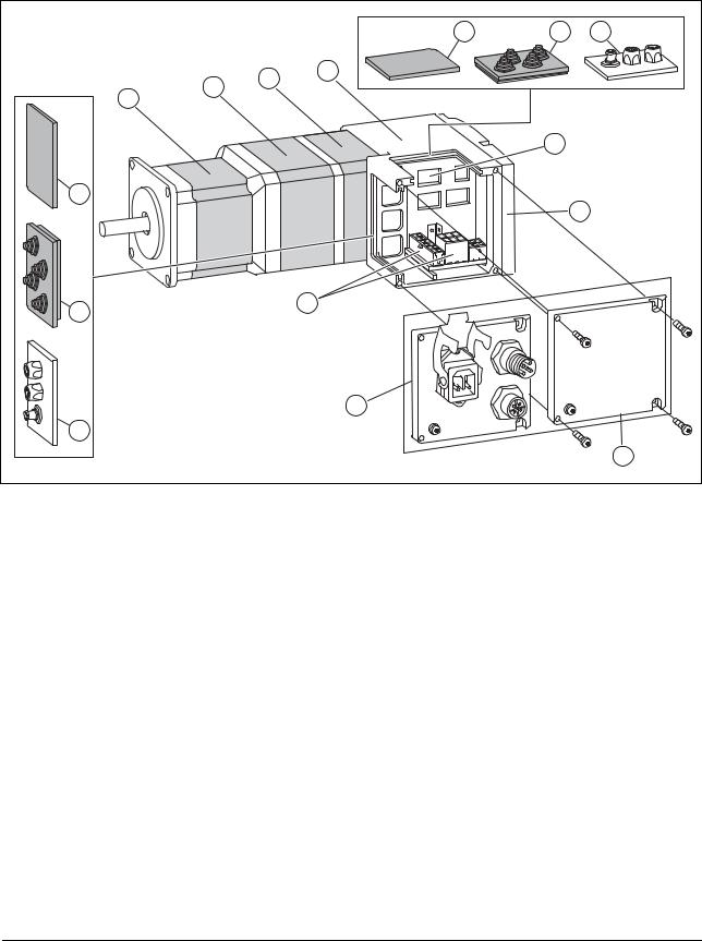
1.3Components and interfaces
|
|
|
5 |
6 |
7 |
|
2 |
3 |
4 |
|
|
|
|
|
|
||
|
|
|
|
|
|
|
1 |
|
|
|
|
|
|
|
|
8 |
|
5 |
|
|
|
|
|
|
|
|
|
|
9 |
6 |
|
|
12 |
|
|
|
|
|
|
|
|
|
|
|
11 |
|
|
7 |
|
|
|
|
|
|
|
|
|
|
10 |
Figure 1.2 Components and interfaces
(1)Synchronous AC servo motor
(2)Holding brake (optional)
(3)Encoder
(4)Electronics housing
(5)Insert for sealing (accessory)
(6)Insert with cable entry (accessory)
(7)I/O insert with industrial connector (accessory)
(8)Switches for settings
(9)Cover of electronics housing, must not be removed
(10)Cover of connector housing, to be removed for installation
(11)Cover with industrial connector for Vdc supply voltage and IN/ OUT fieldbus connection (optional)
(12)Electrical interfaces
0198441113562, V2.00, 09.2008
12 |
Lexium Integrated Drive |

ILA1B, ILA1F, ILA1R |
1 Introduction |
1.3.1Components
Motor The motor is a brushless AC synchronous servo motor with 3-phase technology. The motor has a high power density due to the use of the latest magnetic materials and an optimized design.
Encoder The standard drive system operates with a singleturn encoder.
The singleturn encoder has an internal resolution of 16384 increments per revolution.
The drive system can optionally be equipped with a multiturn encoder.
The multiturn encoder covers a range of 4096 motor revolutions.
Electronics The electronic system comprises control electronics and power stage.
They have a common power supply and are not galvanically isolated.
The drive can be parameterized and controlled via the fieldbus interface.
4 digital 24V signals are also available. Each of them can be used as an input or output.
Holding brake The drive can optionally be equipped with an integrated holding brake. The holding brake is controlled automatically.
0198441113562, V2.00, 09.2008
Lexium Integrated Drive |
13 |

1 Introduction |
ILA1B, ILA1F, ILA1R |
1.3.2Interfaces
Standard available interfaces:
Supply voltage VDC The supply voltage VDC supplies the control electronics and the power stage.
The ground connections of all interfaces are galvanically connected. For more information see chapter 5.2 "Ground design". This chapter also provides information on protection against reverse polarity.
Fieldbus interface Functions:
• Profibus DP connection
• CAN bus connection
• RS485 bus connection
The fieldbus interface is used for parameterizing and controlling the drive. The fieldbus interface allows the drive to be integrated into a fieldbus network and controlled by a master such as a PLC.
The drive can be commissioned via any of the above interfaces. This requires, for example, a PC with a suitable fieldbus converter (e.g. USBCAN). The commissioning software is available for PCs; it supports the various fieldbus versions.
The firmware can be updated via any of the interfaces.
24 V signal interface 4 digital 24V signals are available. Each of them can be used as an input or outputs.
The 24V signals are availab le to the master controller. However, it is also possible to parameterize special functions such as connection of limit switches.
0198441113562, V2.00, 09.2008
14 |
Lexium Integrated Drive |
ILA1B, ILA1F, ILA1R |
1 Introduction |
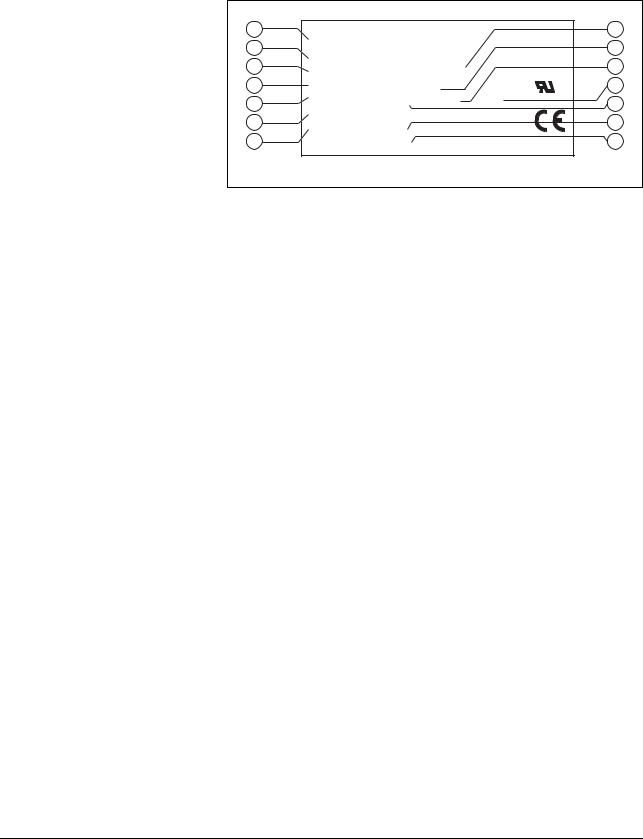
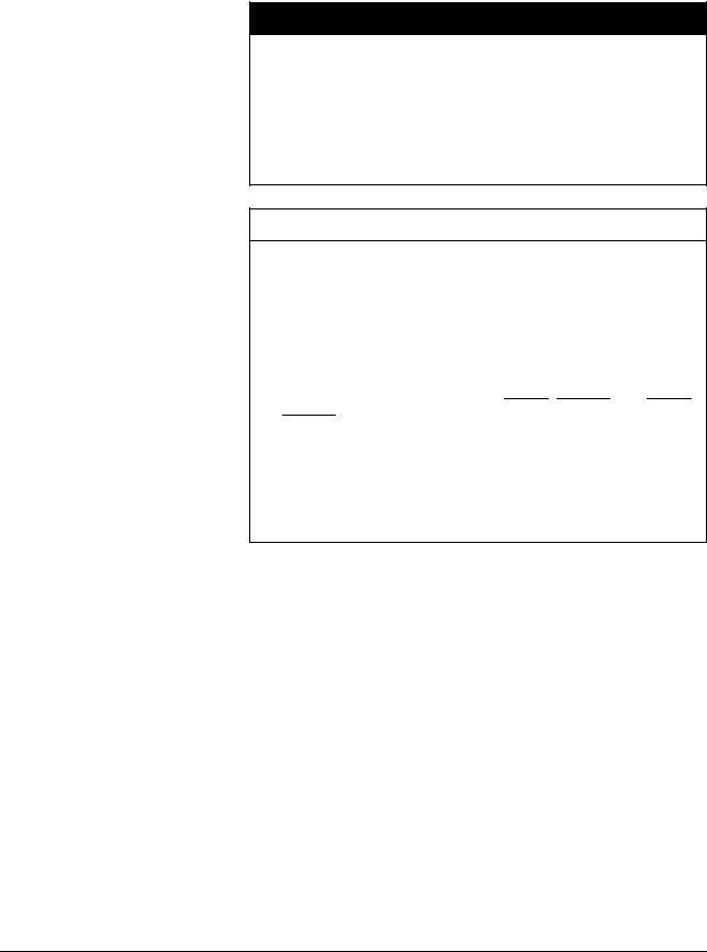
1.4Name plate
The nameplate contains the following data:
1 |
IL ... |
|
|
|
|
8 |
2 |
|
|
|
|
9 |
|
3 |
I ... |
|
|
|
|
10 |
UN |
Insulation class |
|
|
|||
4 |
|
|
11 |
|||
MN |
Tambmax |
|
C |
US |
||
5 |
Imax |
PR |
Rev |
RS |
|
12 |
6 |
nN |
|
|
|
|
13 |
DOM |
ID |
|
|
|
||
7 |
|
|
|
14 |
||
|
SN |
|
made in Germany |
|||
Figure 1.3 |
Nameplate |
|
|
|
|
|
(1)Type code
(2)Type code (old designation)
(3)Nominal voltage
(4)Nominal torque
(5)Maximum input current
(6)Nominal speed
(7)Date of manufacture
(8)Thermal class
(9)Maximum ambient air temperature
(10)Software revision
(11)Hardware revision
(12)Firmware number
(13)Material number
(14)Serial Number
0198441113562, V2.00, 09.2008
Lexium Integrated Drive |
15 |

1 Introduction |
|
|
|
|
|
|
ILA1B, ILA1F, ILA1R |
||||
1.5 |
Type code |
|
|
|
|
|
|
|
|
|
|
|
ILA |
1 |
F |
57 |
1 |
P |
B |
1 |
A |
0 |
-- |
Motor |
|
|
|
|
|
|
|
|
|
|
|
ILA = Servo motor |
|
|
|
|
|
|
|
|
|
|
|
Supply voltage |
|
|
|
|
|
|
|
|
|
|
|
1 = 24 ... 36 VDC |
|
|
|
|
|
|
|
|
|
|
|
Communication interface |
|
|
|
|
|
|
|
|
|
|
|
B = PROFIBUS DP |
|
|
|
|
|
|
|
|
|
|
|
F = CANopen DS301 |
|
|
|
|
|
|
|
|
|
|
|
R = RS485 |
|
|
|
|
|
|
|
|
|
|
|
Size |
|
|
|
|
|
|
|
|
|
|
|
57 = 57 mm |
|
|
|
|
|
|
|
|
|
|
|
Length |
|
|
|
|
|
|
|
|
|
|
|
1 = 1 stack |
|
|
|
|
|
|
|
|
|
|
|
2 = 2 stacks |
|
|
|
|
|
|
|
|
|
|
|
Winding |
|
|
|
|
|
|
|
|
|
|
|
P = Medium speed of rotation/medium torque |
|
|
|
|
|
|
|
|
|
|
|
T = High speed of rotation/low torque |
|
|
|
|
|
|
|
|
|
|
|
Connection version |
|
|
|
|
|
|
|
|
|
|
|
B = Printed circuit board connector |
|
|
|
|
|
|
|
|
|
|
|
C = Industrial connector |
|
|
|
|
|
|
|
|
|
|
|
Position capture |
|
|
|
|
|
|
|
|
|
|
|
1 = Servo Singleturn |
|
|
|
|
|
|
|
|
|
|
|
2 = Servo Multiturn 1). |
|
|
|
|
|
|
|
|
|
|
|
Holding brake |
|
|
|
|
|
|
|
|
|
|
|
A = Without holding brake |
|
|
|
|
|
|
|
|
|
|
|
F = With holding brake 2) |
|
|
|
|
|
|
|
|
|
|
|
Gearbox |
|
|
|
|
|
|
|
|
|
|
|
0 = Without gearbox |
|
|
|
|
|
|
|
|
|
|
|
Reserved |
|
|
|
|
|
|
|
|
|
|
|
1)Not available in combination with the holding brake option
2)Not available in combination with the servo multiturn option.
Customized product In the case of a customized product, position 9 is an "S". Positions 10 ... 13 are the number of the customized product.
Example: IL••••••S1234--
0198441113562, V2.00, 09.2008
16 |
Lexium Integrated Drive |

ILA1B, ILA1F, ILA1R |
1 Introduction |
1.6Documentation and literature references
The following manuals belong to this product:
•Product manual, describes the technical data, installation, commissioning and all operating modes and functions.
•Fieldbus manual, description required to integrate the product into a fieldbus.
Source product manuals The current product manuals are available for download from the Internet.
http://www.schneider-electric.com
Source EPLAN Macros For easier engineering, macro files and product master data are available for download from the Internet at:
http://www.schneider-electric.com
Additional literature We recommend the following literature for more in-depth information:
•Ellis, George: Control System Design Guide. Academic Press
•Kuo, Benjamin; Golnaraghi, Farid: Automatic Control Systems. John Wiley & Sons
0198441113562, V2.00, 09.2008
Lexium Integrated Drive |
17 |
1 Introduction |
ILA1B, ILA1F, ILA1R |
1.7Declaration of conformity
SCHNEIDER ELECTRIC MOTION DEUTSCHLAND GmbH & Co. KG
Breslauer Str. 7 D-77933 Lahr
EC DECLARATION OF CONFORMITY
YEAR 2008
 according to EC Directive Machinery 98/37/EC
  according to EC Directive EMC 2004/108/EC according to EC Directive Low Voltage 2006/95/EC
We declare that the products listed below meet the requirements of the mentioned EC Directives with respect to design, construction and version distributed by us. This declaration becomes invalid with any modification on the products not authorized by us.
Designation: |
Motors with integrated control electronics |
|
|
Type: |
ILA, ILE, ILS |
|
|
Product number: |
0x6600xxxxxxx, 0x6610xxxxxxx, 0x66206xxxxxx, 0x66307xxxxxx |
|
0x6640xxxxxxx, 0x66606xxxxxx, 0x66707xxxxxx |
|
|
Applied |
EN ISO 13849-1:2006, Performance Level "d" (category 3) |
harmonized |
EN 61800-3:2004, second environment |
standards, |
EN 62061:2005, SILcl 2 |
especially: |
EN 61508:2001, SIL 2 |
|
|
Applied |
UL 508C |
national standards |
Product documentation |
and technical |
|
specifications, |
|
especially: |
|
|
|
Company stamp: |
|
Date/ Signature: |
10 July 2008 |
Name/ Department: Wolfgang Brandstätter/Development
0198441113562, V2.00, 09.2008
18 |
Lexium Integrated Drive |

ILA1B, ILA1F, ILA1R |
1 Introduction |
1.8TÜV certificate for functional safety
0198441113562, V2.00, 09.2008
Lexium Integrated Drive |
19 |

1 Introduction |
ILA1B, ILA1F, ILA1R |
0198441113562, V2.00, 09.2008
20 |
Lexium Integrated Drive |
ILA1B, ILA1F, ILA1R |
2 Before you begin - safety information |
2 Before you begin - safety information
2.1Qualification of personnel
Only appropriately trained persons who are familiar with and understand the contents of this manual and all other pertinent product documentation are authorized to work on and with this product. In addition, these persons must have received safety training to recognize and avoid hazards involved. These persons must have sufficient technical training, knowledge and experience and be able to foresee and detect potential hazards that may be caused by using the product, by changing the settings and by the mechanical, electrical and electronic equipment of the entire system in which the product is used.
All persons working on and with the product must be fully familiar with all applicable standards, directives, and accident prevention regulations when performing such work.
2.2Intended use
This product is a motor with an integrated drive and intended for industrial use according to this manual.
The product may only be used in compliance with all applicable safety regulations and directives, the specified requirements and the technical data.
Prior to using the product, you must perform a risk assessment in view of the planned application. Based on the results, the appropriate safety measures must be implemented.
Since the product is used as a component in an entire system, you must ensure the safety of persons by means of the design of this entire system (e.g. machine design).
Operate the product only with the specified cables and accessories. Use only genuine accessories and spare parts.
The product must NEVER be operated in explosive atmospheres (hazardous locations, Ex areas).
Any use other than the use explicitly permitted is prohibited and can result in hazards.
Electrical equipment should be installed, operated, serviced, and maintained only by qualified personnel.
0198441113562, V2.00, 09.2008
Lexium Integrated Drive |
21 |
2 Before you begin - safety information |
ILA1B, ILA1F, ILA1R |
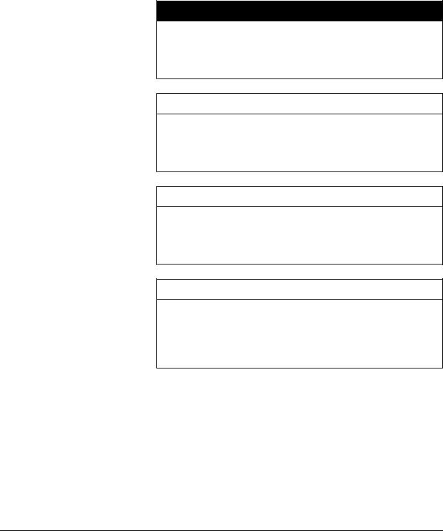
2.3Hazard categories
Safety instructions to the user are highlighted by safety alert symbols in the manual. In addition, labels with symbols and/or instructions are attached to the product that alert you to potential hazards.
Depending on the seriousness of the hazard, the safety instructions are divided into 4 hazard categories.
@ DANGER
DANGER indicates an imminently hazardous situation, which, if not avoided, will result in death or serious injury.
@ WARNING
WARNING indicates a potentially hazardous situation, which, if not avoided, can result in death, serious injury, or equipment damage.
@ CAUTION
CAUTION indicates a potentially hazardous situation, which, if not avoided, can result in injury or equipment damage.
CAUTION
CAUTION used without the safety alert symbol, is used to address practices not related to personal injury (e.g. can result in equipment damage).
0198441113562, V2.00, 09.2008
22 |
Lexium Integrated Drive |
ILA1B, ILA1F, ILA1R |
2 Before you begin - safety information |
2.4Basic information
@ DANGER
UNINTENDED CONSEQUENCES OF EQUIPMENT OPERATION
When the system is started, the drives are usually out of the operator's view and cannot be visually monitored.
•Only start the system if there are no persons in the hazardous area.
Failure to follow these instructions will result in death or serious injury.
@ WARNING
UNEXPECTED MOVEMENT
Drives may perform unexpected movements because of incorrect wiring, incorrect settings, incorrect data or other errors.
Interference (EMC) may cause unpredictable responses in the system.
•Carefully install the wiring in accordance with the EMC requirements.
•Switch off the voltage at the inputs STO_A (PWRR_A) and STO_B (PWRR_B) to avoid an unexpected restart of the motor before switching on and configuring the drive system.
•Do NOT operate the drive system with unknown settings or data.
•Perform a comprehensive commissioning test.
Failure to follow these instructions can result in death or serious injury.
0198441113562, V2.00, 09.2008
Lexium Integrated Drive |
23 |

2 Before you begin - safety information |
ILA1B, ILA1F, ILA1R |
@ WARNING
LOSS OF CONTROL
•The designer of any control scheme must consider the potential failure modes of control paths and, for certain critical functions, provide a means to achieve a safe state during and after a path failure. Examples of critical control functions are EMERGENCY STOP, overtravel stop, power outage and restart.
•Separate or redundant control paths must be provided for critical functions.
•System control paths may include communication links. Consideration must be given to the implication of unanticipated transmission delays or failures of the link.
•Observe the accident prevention regulations and local safety guidelines. 1)
•Each implementation of the product must be individually and thoroughly tested for proper operation before being placed into service.
Failure to follow these instructions can result in death or serious injury.
1)For USA: Additional information, refer to NEMA ICS 1.1 (latest edition), Safety Guidelines for the Application, Installation, and Maintenance of Solid State Control and to NEMA ICS 7.1 (latest edition), Safety Standards for Construction and Guide for Selection, Installation for Construction and Operation of AdjustableSpeed Drive Systems.
@ CAUTION
UNEXPECTED BEHAVIOR AND DESTRUCTION OF SYSTEM COMPO-
NENTS
When you work on the wiring and when you unplug or plug in connectors, this may cause unexpected behavior and destruction of system components.
•Switch the power supply off before working on the wiring.
Failure to follow these instructions can result in injury or equipment damage.
2.5Functional safety
Using the safety functions integrated in this product requires careful planning. For more information see chapter5.3 "Safety function STO ("Safe Torque Off")" on page 40.
0198441113562, V2.00, 09.2008
24 |
Lexium Integrated Drive |

ILA1B, ILA1F, ILA1R |
2 Before you begin - safety information |
2.6Standards and terminology
Technical terms, terminology and the corresponding descriptions in this manual are intended to use the terms or definitions of the pertinent standards.
In the area of drive systems, this includes, but is not limited to, terms such as "safety function", "safe state", "fault", "fault reset", "failure", "error", "error message", "warning", "warning message", "alarm", etc.
Among others, these standards include:
•IEC 61800 series: "Adjustable speed electrical power drive systems"
•IEC 61800-7 series: "Adjustable speed electrical power drive systems - Part 7-1: Generic interface and use of profiles for power drive systems - Interface definition"
•IEC 61158 series: "Industrial communication networks - Fieldbus specifications"
•IEC 61784 series: "Industrial communication networks - Profiles"
•IEC 61508 series: "Functional safety of electrical/electronic/programmable electronic safety-related systems"
Also see the glossary at the end of this manual.
0198441113562, V2.00, 09.2008
Lexium Integrated Drive |
25 |

2 Before you begin - safety information |
ILA1B, ILA1F, ILA1R |
0198441113562, V2.00, 09.2008
26 |
Lexium Integrated Drive |

ILA1B, ILA1F, ILA1R |
3 Technical Data |
0198441113562, V2.00, 09.2008
3 Technical Data
This chapter contains information on the ambient conditions and on the mechanical and electrical properties of the device family and the accessories.
3.1Certifications
Product certifications:
Certified by |
Assigned number |
Validity |
TÜV Nord |
SAS-1728/08 |
2013-01-09 |
|
|
|
UL |
File E 153659 |
|
|
|
|
Certified safety function This product has the following certified safety function:
•Safety function STO "Safe Torque Off" (IEC 61800-5-2)
3.2Ambient conditions
Ambient temperature during operation
The maximum permissible ambient temperature during operation depends on the distance between the devices and the required power. Observe the pertinent instructions in the chapter Installation.
Operating temperature 1) 2) |
[°C] |
0 ... 50 |
Operating temperature with cur- |
[°C] |
50 ... 65 |
rent reduction of 2% per Kelvin 1) |
|
|
1)Limit values with flanged motor (steel plate 300x300x10 mm)
2)If the product is to be used in compliance with UL 508C, note the information provided in chapter 3.5 "Conditions for UL 508C".
Ambient conditions transportation and storage
Temperature
The environment during transport and storage must be dry and free from dust. The maximum vibration and shock load must be within the specified limits.
Temperature |
[°C] -25 ... +70 |
|
|
|
|
Max. temperature of power |
[°C] |
105 |
stage 1) |
|
|
Max. temperature of motor 2) |
[°C] |
110 |
1)Can be read via parameter
2)Measured on the surface
Relative humidity The following relative humidity is permissible during operation:
Relative humidity (non-condens- [%] |
15 ... 85 |
ing) |
|
|
|
Lexium Integrated Drive |
27 |

3 Technical Data |
ILA1B, ILA1F, ILA1R |
Installation altitude The installation altitude is defined as height above sea level.
Installation altitude [m] ≤1000
Vibration and shock
Vibartion, sinusoidal |
As per IEC/EN 60068-2-6 |
|
0.15 mm (from 10 Hz ... 60 Hz) |
|
20 m/s2 (from 10 Hz ... 500 Hz) |
Shock, semi-sinusoidal |
As per IEC/EN 60068-2-27: |
|
150 m/s2 (11 ms) |
EMC
Emission |
IEC/EN 61800-3: Class C2 |
|
EN 61000-6-4 |
|
EN 55022: Class A |
|
|
Noise immunity |
IEC/EN 61800-3: Second environment |
|
|
0198441113562, V2.00, 09.2008
28 |
Lexium Integrated Drive |
ILA1B, ILA1F, ILA1R |
3 Technical Data |
3.3Mechanical data
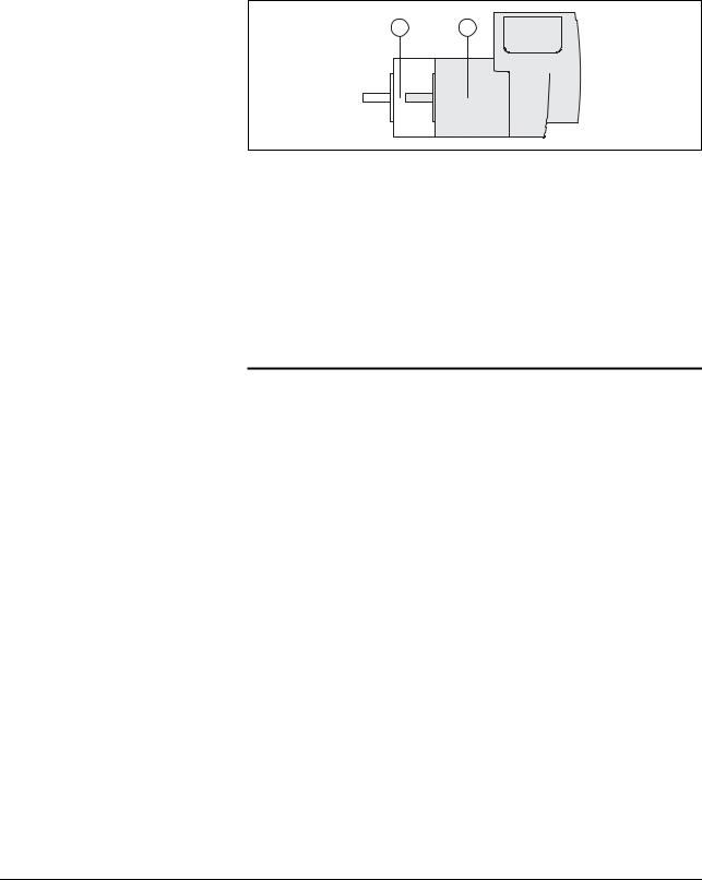
3.3.1Degree of protection
IP degree of protection The product has the following IP degree of protection as per EN 60529.
1 2
0198441113562, V2.00, 09.2008
Overview of IP degrees of protection
Degree of protection if STO is used
Figure 3.1 |
IP degree of protection |
|
|
|
|
|
|
Item |
|
|
Degree of |
|
|
|
protection |
|
|
|
|
1 |
Shaft bushing |
IP41 |
|
|
Shaft bushing with GBX gear (accessory) |
IP54 |
|
|
|
|
|
2 |
Housing, except shaft bushing |
IP54 |
|
|
|
|
|
The total degree of protection is determined by the component with the lowest degree of protection.
First digit |
Second digit |
|||
Protection against intrusion of |
|
Protection against intrusion of water |
||
objects |
|
|
|
|
|
|
|
|
|
0 |
No protection |
0 |
No protection |
|
|
|
|
|
|
1 |
External objects >50 mm |
1 |
Vertically falling dripping water |
|
|
|
|
|
|
2 |
External objects >12 mm |
2 |
Dripping water falling at an angle |
|
|
|
|
|
(75 ° ... 90 °) |
|
|
|
|
|
3 |
External objects >2.5 mm |
3 |
Spraying water |
|
|
|
|
|
|
4 |
External objects >1 mm |
4 |
Splashing water |
|
|
|
|
|
|
5 |
Dust-protected |
5 |
Water jets |
|
|
|
|
|
|
6 |
Dust-tight |
6 |
Heavy sea |
|
|
|
|
|
|
|
|
7 |
Immersion |
|
|
|
|
|
|
|
|
8 |
Submersion |
|
|
|
|
|
|
You must ensure that conductive substances cannot get into the product (pollution degree 2). If you use the safety function and conductive substances get into the product, the safety function may become inoperative.
Lexium Integrated Drive |
29 |
3 Technical Data |
ILA1B, ILA1F, ILA1R |
3.3.2Mounting position
Mounting position The following mounting positions are defined and approved as per EN 60034-7:
•IM B5 drive shaft horizontal
•IM V1 drive shaft vertical, shaft end down
•IM V3 drive shaft vertical, shaft end up
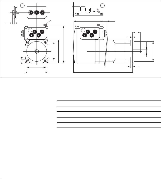
3.3.3Dimensions
|
2 |
|
|
|
3 |
|
|
|
|
|
17 |
|
|
5.5 |
M4 |
|
|
73 |
9.5 |
|
|
|
|
|
|
|
|
|
1 |
|
|
1 |
20 |
|
|
|
|
|
|
1.6 |
|
Ø5.2 |
47.14 |
57.2 |
92.2 |
|
Ø9 j6 |
Ø50 h8 |
|
47.14 |
|
|
|
5.8 |
|
|
|
|
|
|
|
|
|
57.2 |
|
|
|
L |
|
|
|
Figure 3.2 |
Dimensions |
|
|
|
(1)Insert with cable entry (accessory)
(2)Insert kit (accessory)
(3)Industrial connector (option)
Total length L |
|
••1A0 |
••2A0 |
••1F0 |
ILA••571... |
|
|||
L |
[mm] |
145.3 |
179.3 |
190.8 |
ILA••572... |
|
••1A0 |
••2A0 |
••2F0 |
L |
[mm] |
163.8 |
197.8 |
209.3 |
0198441113562, V2.00, 09.2008
30 |
Lexium Integrated Drive |
Loading...