


Communication Drivers
Installation manual
eng
35006152 00

2

Table of Contents
About the Book. . . . . . . . . . . . . . . . . . . . . . . . . . . . . . . . . . . . . . .7
Part I General information on the installation of drivers . . . . . 9
At a Glance . . . . . . . . . . . . . . . . . . . . . . . . . . . . . . . . . . . . . . . . . . . . . . . . . . . . . . 9
Chapter 1 General information con c er n i n g th e D ri v e rs . . . . . . . . . . . . . .11
At a Glance . . . . . . . . . . . . . . . . . . . . . . . . . . . . . . . . . . . . . . . . . . . . . . . . . . . . . 11
Installation. . . . . . . . . . . . . . . . . . . . . . . . . . . . . . . . . . . . . . . . . . . . . . . . . . . . . . 12
The drivers and Unity Pro . . . . . . . . . . . . . . . . . . . . . . . . . . . . . . . . . . . . . . . . . . 14
Part II Uni-Telway drivers . . . . . . . . . . . . . . . . . . . . . . . . . . . . . . 15
At a Glance . . . . . . . . . . . . . . . . . . . . . . . . . . . . . . . . . . . . . . . . . . . . . . . . . . . . . 15
Chapter 2 Serial port . . . . . . . . . . . . . . . . . . . . . . . . . . . . . . . . . . . . . . . . . .17
At a Glance . . . . . . . . . . . . . . . . . . . . . . . . . . . . . . . . . . . . . . . . . . . . . . . . . . . . . 17
How to install the driver. . . . . . . . . . . . . . . . . . . . . . . . . . . . . . . . . . . . . . . . . . . . 18
Driver configuration screens . . . . . . . . . . . . . . . . . . . . . . . . . . . . . . . . . . . . . . . . 20
How to configure the driver. . . . . . . . . . . . . . . . . . . . . . . . . . . . . . . . . . . . . . . . . 24
Chapter 3 TSX SCP 114 card. . . . . . . . . . . . . . . . . . . . . . . . . . . . . . . . . . . .27
At a Glance . . . . . . . . . . . . . . . . . . . . . . . . . . . . . . . . . . . . . . . . . . . . . . . . . . . . . 27
How to install the driver. . . . . . . . . . . . . . . . . . . . . . . . . . . . . . . . . . . . . . . . . . . . 28
Driver configuration screens . . . . . . . . . . . . . . . . . . . . . . . . . . . . . . . . . . . . . . . . 30
Configuration of the Windows 98 operating system . . . . . . . . . . . . . . . . . . . . . . 32
Configuration of the Windows 2000\XP operating system . . . . . . . . . . . . . . . . . 33
Configuration of Win NT operating system . . . . . . . . . . . . . . . . . . . . . . . . . . . . . 34
Part III FIP drivers. . . . . . . . . . . . . . . . . . . . . . . . . . . . . . . . . . . . . 35
At a Glance . . . . . . . . . . . . . . . . . . . . . . . . . . . . . . . . . . . . . . . . . . . . . . . . . . . . . 35
Chapter 4 TSX FPP 20 card . . . . . . . . . . . . . . . . . . . . . . . . . . . . . . . . . . . . .37
At a Glance . . . . . . . . . . . . . . . . . . . . . . . . . . . . . . . . . . . . . . . . . . . . . . . . . . . . . 37
How to install the driver. . . . . . . . . . . . . . . . . . . . . . . . . . . . . . . . . . . . . . . . . . . . 38
How to install the driver. . . . . . . . . . . . . . . . . . . . . . . . . . . . . . . . . . . . . . . . . . . . 40
Configuration of the Windows 98 operating system . . . . . . . . . . . . . . . . . . . . . . 41
3

Configuration of the Windows 2000\XP operating system. . . . . . . . . . . . . . . . . . 42
Configuration of the Windows NT operating system . . . . . . . . . . . . . . . . . . . . . . 43
Chapter 5 TSX FPC 10 ISA c a rd . . . . . . . . . . . . . . . . . . . . . . . . . . . . . . . . . 45
At a Glance . . . . . . . . . . . . . . . . . . . . . . . . . . . . . . . . . . . . . . . . . . . . . . . . . . . . . 45
How to install the driver . . . . . . . . . . . . . . . . . . . . . . . . . . . . . . . . . . . . . . . . . . . . 46
Driver configuration screen for Windows NT. . . . . . . . . . . . . . . . . . . . . . . . . . . . 48
Driver configuration screen for Windows 98\2000\XP . . . . . . . . . . . . . . . . . . . . . 50
Configuration of the operating system using the TSX FPC 10 card. . . . . . . . . . 51
How to select the hardware type for Windows 98 . . . . . . . . . . . . . . . . . . . . . . . . 52
How to select the hardware type for Windows 2000\XP . . . . . . . . . . . . . . . . . . . 55
How to configure hardware parameters for Windows 98. . . . . . . . . . . . . . . . . . . 58
How to configure hardware parameters for Windows 2000\XP. . . . . . . . . . . . . . 60
How to adjust the ISA TSX FPC 10 card parameters . . . . . . . . . . . . . . . . . . . . . 63
Part IV ETHWAY driver . . . . . . . . . . . . . . . . . . . . . . . . . . . . . . . . .65
At a Glance . . . . . . . . . . . . . . . . . . . . . . . . . . . . . . . . . . . . . . . . . . . . . . . . . . . . . 65
Chapter 6 Installation . . . . . . . . . . . . . . . . . . . . . . . . . . . . . . . . . . . . . . . . . 67
At a Glance . . . . . . . . . . . . . . . . . . . . . . . . . . . . . . . . . . . . . . . . . . . . . . . . . . . . . 67
How to install the driver for Windows 2000\XP . . . . . . . . . . . . . . . . . . . . . . . . . . 68
How to install the driver for Windows NT. . . . . . . . . . . . . . . . . . . . . . . . . . . . . . . 71
Driver configuration tool. . . . . . . . . . . . . . . . . . . . . . . . . . . . . . . . . . . . . . . . . . . . 73
Part V XIP driver on TCP/IP . . . . . . . . . . . . . . . . . . . . . . . . . . . . .75
At a Glance . . . . . . . . . . . . . . . . . . . . . . . . . . . . . . . . . . . . . . . . . . . . . . . . . . . . . 75
Chapter 7 Installation . . . . . . . . . . . . . . . . . . . . . . . . . . . . . . . . . . . . . . . . . 77
At a Glance . . . . . . . . . . . . . . . . . . . . . . . . . . . . . . . . . . . . . . . . . . . . . . . . . . . . . 77
How to install the driver . . . . . . . . . . . . . . . . . . . . . . . . . . . . . . . . . . . . . . . . . . . . 78
Driver configuration screen . . . . . . . . . . . . . . . . . . . . . . . . . . . . . . . . . . . . . . . . . 80
How to configure the driver . . . . . . . . . . . . . . . . . . . . . . . . . . . . . . . . . . . . . . . . . 82
Part VI Drivers for Atrium Processors . . . . . . . . . . . . . . . . . . . . .85
At a Glance . . . . . . . . . . . . . . . . . . . . . . . . . . . . . . . . . . . . . . . . . . . . . . . . . . . . . 85
Chapter 8 ISAWAY driver for TPCX 57 processors . . . . . . . . . . . . . . . . . 87
At a Glance . . . . . . . . . . . . . . . . . . . . . . . . . . . . . . . . . . . . . . . . . . . . . . . . . . . . . 87
How to install the driver . . . . . . . . . . . . . . . . . . . . . . . . . . . . . . . . . . . . . . . . . . . . 88
Configuration of the ISAWAY driver for Windows NT . . . . . . . . . . . . . . . . . . . . . 90
Configuration of ISAWAY driver for Windows 98\2000\XP . . . . . . . . . . . . . . . . . 95
Configuration of the operating system. . . . . . . . . . . . . . . . . . . . . . . . . . . . . . . . . 96
How to select the hardware type for Windows 98 . . . . . . . . . . . . . . . . . . . . . . . . 97
How to select the hardware type for Windows 2000\XP . . . . . . . . . . . . . . . . . . 100
How to configure hardware parameters for Windows 98. . . . . . . . . . . . . . . . . . 103
How to configure hardware parameters for Windows 2000\XP. . . . . . . . . . . . . 105
4

How to adjust the ISA TPCX 57 card parameters. . . . . . . . . . . . . . . . . . . . . . . 108
Chapter 9 PCIWAY driver for TSX PCI 57 ••• processors . . . . . . . . . . . .111
At a Glance . . . . . . . . . . . . . . . . . . . . . . . . . . . . . . . . . . . . . . . . . . . . . . . . . . . . 111
How to install the driver. . . . . . . . . . . . . . . . . . . . . . . . . . . . . . . . . . . . . . . . . . . 112
Configuring the PCIWAY driver for windows 2000\XP . . . . . . . . . . . . . . . . . . . 114
How to adjust the parameters of the TSX PCI 57 ••• card. . . . . . . . . . . . . . . . . 116
Part VII Modbus driver. . . . . . . . . . . . . . . . . . . . . . . . . . . . . . . . . 119
At a Glance . . . . . . . . . . . . . . . . . . . . . . . . . . . . . . . . . . . . . . . . . . . . . . . . . . . . 119
Chapter 10 Installation. . . . . . . . . . . . . . . . . . . . . . . . . . . . . . . . . . . . . . . . .121
At a Glance . . . . . . . . . . . . . . . . . . . . . . . . . . . . . . . . . . . . . . . . . . . . . . . . . . . . 121
How to install the driver. . . . . . . . . . . . . . . . . . . . . . . . . . . . . . . . . . . . . . . . . . . 122
Driver configuration screen . . . . . . . . . . . . . . . . . . . . . . . . . . . . . . . . . . . . . . . . 124
Driver control screen. . . . . . . . . . . . . . . . . . . . . . . . . . . . . . . . . . . . . . . . . . . . . 126
Driver debug screen . . . . . . . . . . . . . . . . . . . . . . . . . . . . . . . . . . . . . . . . . . . . . 128
Information screen. . . . . . . . . . . . . . . . . . . . . . . . . . . . . . . . . . . . . . . . . . . . . . . 130
Part VIII USB driver. . . . . . . . . . . . . . . . . . . . . . . . . . . . . . . . . . . . 131
At a Glance . . . . . . . . . . . . . . . . . . . . . . . . . . . . . . . . . . . . . . . . . . . . . . . . . . . . 131
Chapter 11 Installation. . . . . . . . . . . . . . . . . . . . . . . . . . . . . . . . . . . . . . . . .133
At a Glance . . . . . . . . . . . . . . . . . . . . . . . . . . . . . . . . . . . . . . . . . . . . . . . . . . . . 133
How to install the driver. . . . . . . . . . . . . . . . . . . . . . . . . . . . . . . . . . . . . . . . . . . 134
Configuration screens for Win 2000\XP . . . . . . . . . . . . . . . . . . . . . . . . . . . . . . 137
State of the USB link. . . . . . . . . . . . . . . . . . . . . . . . . . . . . . . . . . . . . . . . . . . . . 139
Part IX Drivers manager. . . . . . . . . . . . . . . . . . . . . . . . . . . . . . . 141
At a Glance . . . . . . . . . . . . . . . . . . . . . . . . . . . . . . . . . . . . . . . . . . . . . . . . . . . . 141
Chapter 12 Functions. . . . . . . . . . . . . . . . . . . . . . . . . . . . . . . . . . . . . . . . . .143
Management of X-Way drivers . . . . . . . . . . . . . . . . . . . . . . . . . . . . . . . . . . . . . 143
Appendices . . . . . . . . . . . . . . . . . . . . . . . . . . . . . . . . . . . . . . . . . . . . . 147
At a Glance . . . . . . . . . . . . . . . . . . . . . . . . . . . . . . . . . . . . . . . . . . . . . . . . . . . . 147
Appendix A The drivers of the TSX PCX 3030 cable . . . . . . . . . . . . . . . . .149
At a Glance . . . . . . . . . . . . . . . . . . . . . . . . . . . . . . . . . . . . . . . . . . . . . . . . . . . . 149
Installing the drivers of the TSX PCX 3030 cable . . . . . . . . . . . . . . . . . . . . . . . 150
Configuration screens for drivers using the TSX PCX 3030 cable.. . . . . . . . . . 154
Index . . . . . . . . . . . . . . . . . . . . . . . . . . . . . . . . . . . . . . . . . . . . . 157
5

6
About the Book
At a Glance
Document Scope This document deals with the insta llation o f communic ation driv ers for Wi ndows 98,
Windows 2000/XP and Windows NT operating systems.
These drivers are:
l
Uni-Telway:
l
on the serial port,
l
with a TSXSCP114 card.
l
Fip:
l
with a TSXFPC10 card,
l
with a TSXFPP20 card.
l
Ethway,
l
XIP on TCPIP,
l
drivers for Atrium:
l
Isaway for the ISA bus,
l
PCIWAY for the PCI bus.
l
Modbus,
l
USB.
Validity Note The data and illustrations found in this documentation are not binding. We reserve
the right to modify our products in line with our policy of continuous product
development.
The information in th is documen t is subje ct to cha nge without notice and should n ot
be construed as a commitment by Schneider Electric.
Related
Documents
7
Title of Documentation Reference Number
X-Way Driver TLX DI XIP M

About the Book
Product Related
Warnings
Schneider Electric assumes no res po ns ibi lit y for an y errors that may appear in this
document. If you have any suggestions for improvements or amendments or have
found errors in this publication, please notify us.
No part of this document may be reproduced in any form or by any means, electron ic
or mechanical, including photocopying, without express written permission of
Schneider Electric.
All pertinent state, regional, and local safety regulations must be observed when
installing and using this product.
For reasons of safe ty and to en sure compli ance with doc umented syst em data, only
the manufacturer should perform repairs to components.
When controllers are used for applications with technical safety requirements,
please follow the relevant instructions.
Failure to observe this product related warning can result in injury or equipment
damage.
User Comments We welcome your comments about this document. You can reach us by e-mail at
TECHCOMM@modicon.com
8

At a Glance
General information on the installation of drivers
I
Subject of this
Part
What’s in this
Part?
This part describes the installation principle of the various drivers using the
CD ROM.
This part contains the following chapters:
Chapter Chapter Name Page
1 General information concerning the Drivers 11
9

General
10

At a Glance
General information concerning the Drivers
1
Subject of this
chapter
What’s in this
Chapter?
This chapter provides general information on the drivers.
This chapter contains the following topics:
Topic Page
Installation 12
The drivers and Unity Pro 14
11
General information concerning the Drivers
Installation
At a Glance It is generally possible to launch the installation of all the drivers using the same
procedure.
Procedure The following procedure describes the installation principle of a driver using the
CD ROM.
Step Description
1 Insert the CD ROM in the CD ROM drive.
Result: the Install.htm file launches automatically.
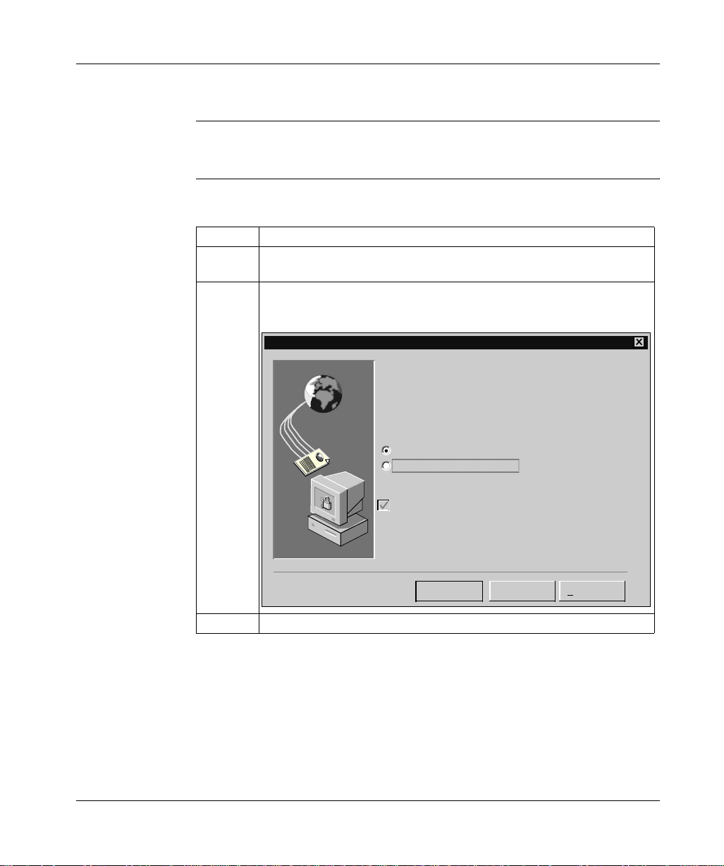
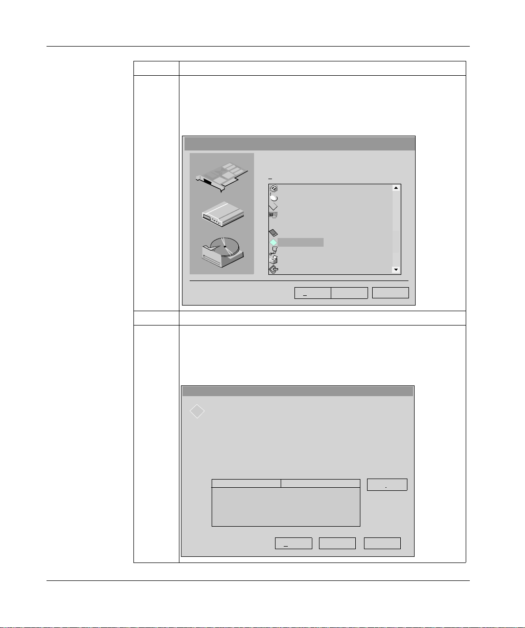
2 Click on the link (in blue underlined text) that corresponds to the driver you wish
to install.
Result: the Downloading files window appears.
Downloading a file
You have chosen to download a file from this location.
SETUP.EXE from D:\CD_Rom\Install.htm
What do you wish to do with this file?
Run this program from its current location
Save this program on the disk
12
Always ask before opening this type of file
OK Further info.
3 Choose Run this program from its curren t location.
Cancel
Step Description
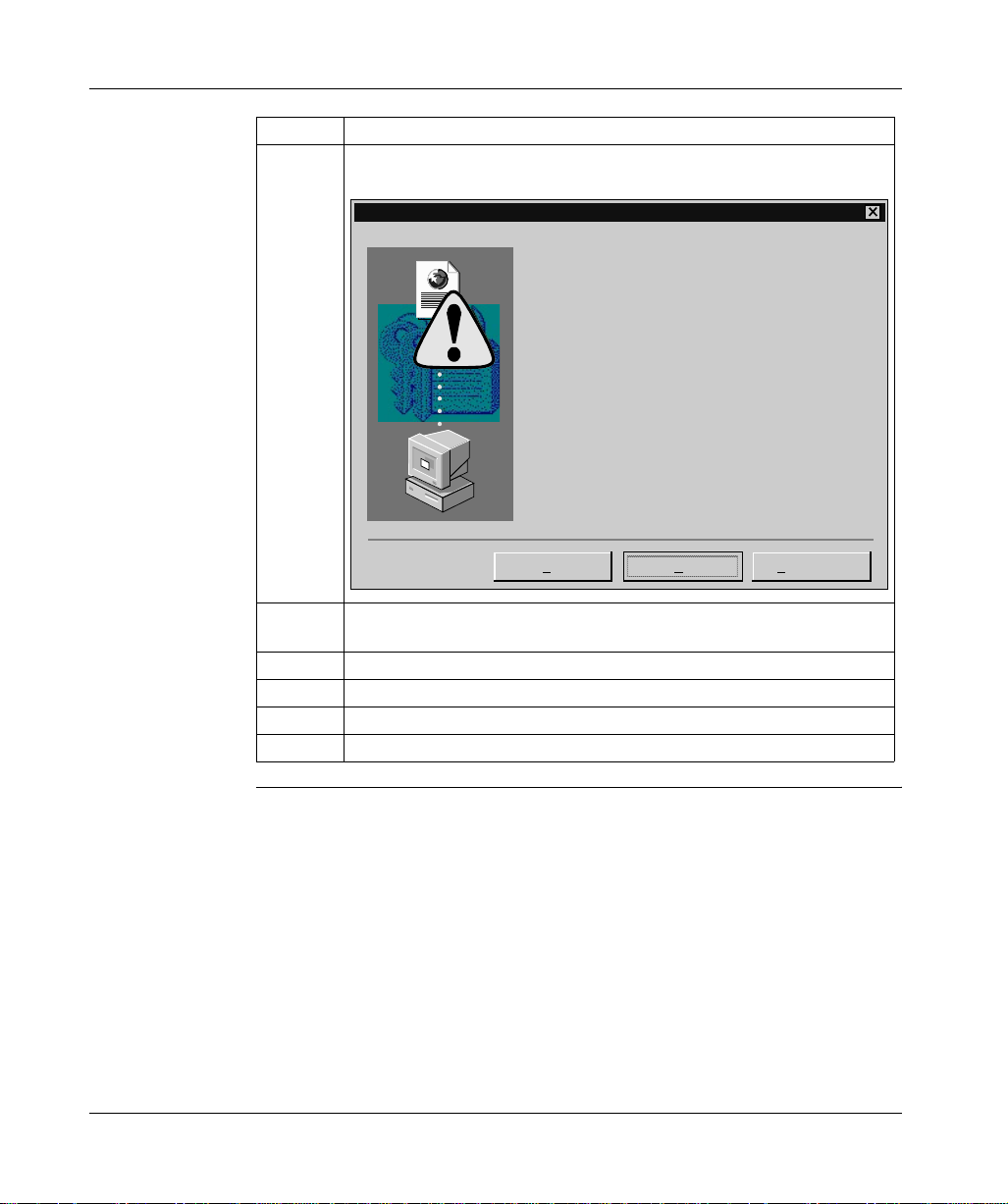
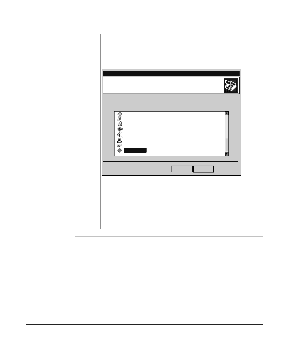
4 Then click on OK to confirm your choice.
Result: the Safety warning window appears.
Security warning
Do you wish to install and run "SETUP.EXE from
D:\
CDRom\UNITELWAY\Win2000-XP-Win 98-Me\disk1"?
Impossible to identify this editor for the following reasons:
The object to be verified is unknown to the supplier of
reliability certificates.
Y
es No Further info.
5 Click on Yes to go ahead with the installation.
Result: the installation setup of the chosen driver is run.
6 Click on Next to go ahead with the installation.
7 Configure the driver.
8 Then click on OK to confirm the configuration.
9 Restart your computer.
General information concerning the Drivers
13

General information concerning the Drivers
The drivers and Unity Pro
Precautions To ensure correct operation of the drivers using the Unity Pro software range you
should install or reinstall the drivers using the CDROM version ≥ V2.0.
Drivers that normally operate using the Unity Pro software range should also be
installed using Windows XP or Windows 2000.
14

At a Glance
Uni-Telway drivers
II
Subject of this
Part
What’s in this
Part?
This part describes how to install the drivers associated with Uni-Telway
communication for Windows 98, Windows 2000\XP and Windows NT operating
systems.
This part contains the following chapters:
Chapter Chapter Name Page
2 Serial port 17
3 TSX SCP 114 card 27
15

Uni-Telway drivers
16
At a Glance
Serial port
2
Subject of this
Chapter
What’s in this
Chapter?
This chapter describes instal lation of the Uni -Tel way driv er commu nicat ing in s lave
mode on the serial port with a remote device.
Driver installation consists of two steps:
l
installation of files on the station,
l
configuration of the driver.
This chapter contains the following topics:
Topic Page
How to install the driver 18
Driver configuration screens 20
How to configure the driver 24
17

Serial port
How to install the driver
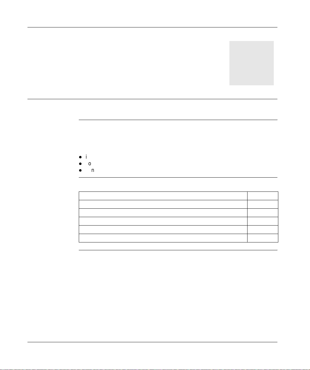
At a Glance Driver installation is a standard installation. It can be launched either:
l
from the drivers’ CD-ROM,
l
or from disks if the station has no CD-ROM drive.
Note: The installation disks are created from the CD-ROM.
How to create a
set of disks
Preliminary
operations
Use the following procedure to create installation disks:
Step Action
1 Use a station with a CD-ROM drive.
2 Insert the CD-ROM into the drive.
3 Access the directory of the driver to be copied onto disk.
4 Copy the contents of the DISK1 directory onto a disk. Repeat this step for each
DISK directory.
Note: it is advisable to number the disks.
Before installing the new driver, you must check that no other version of this driver
exists on the station.
If a driver does exist, you must delete it before carrying out the new installation.
A previous version can be uninstalled using:
l
Drivers Manager software,
l
or the Control Panel → Add/Remove Programs.
18
Serial port
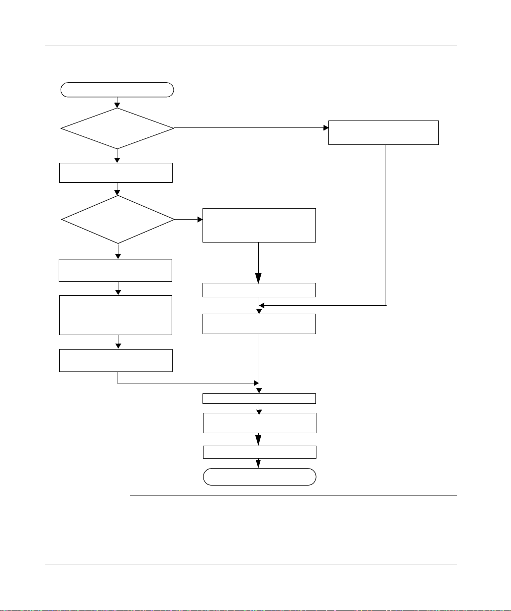
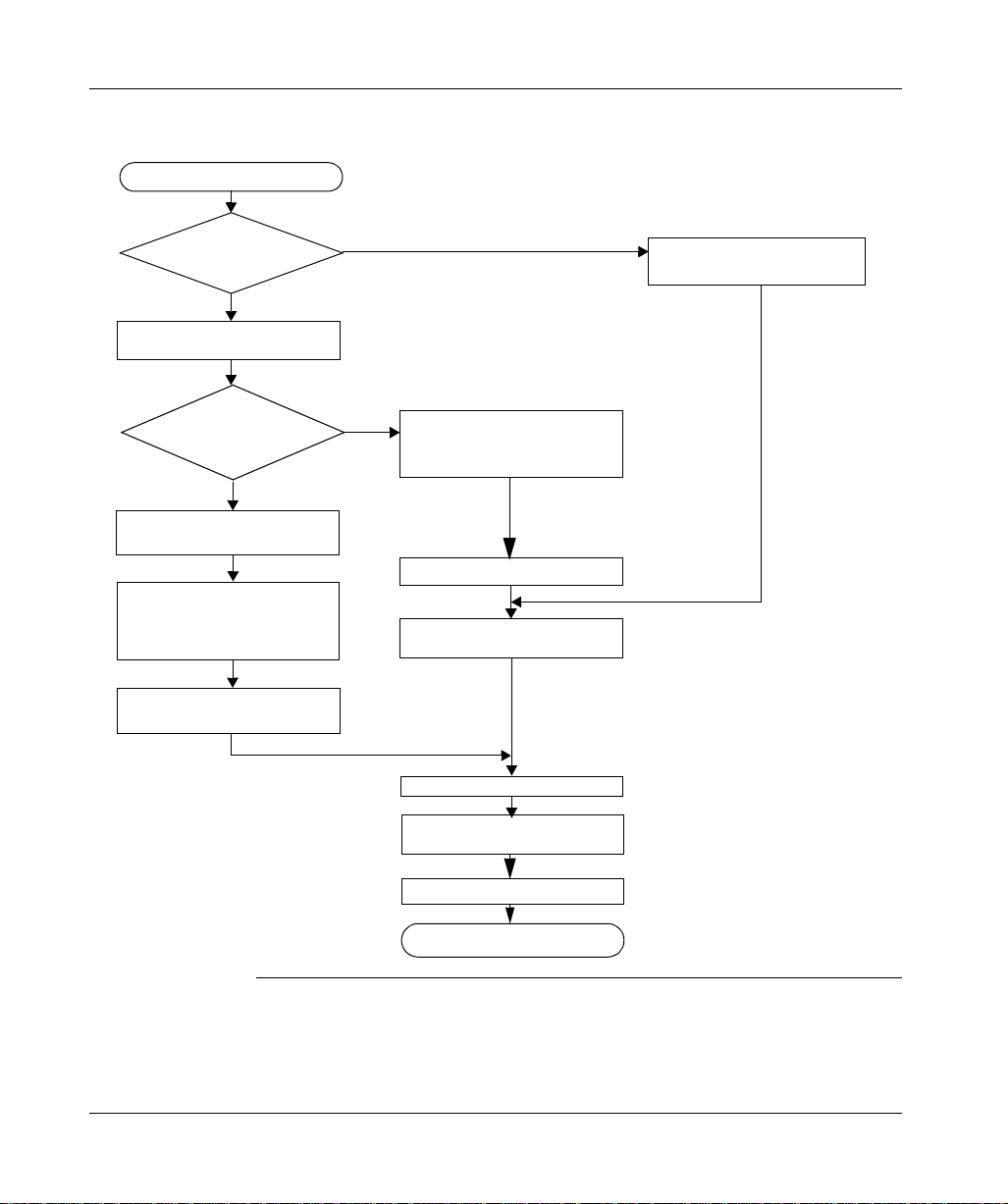
How to install the
To install the driver, carry out the following procedure:
driver
Start of installation
Installation by
CD-ROM?
Yes
Insert CD-ROM in CD-ROM drive
Appearance
of the file
INSTALL.HTM
?
Yes
Click on the link which corresponds
to the driver to be installed
Choose Run this program from
its current location then confirm
by clicking on OK
No
No
Access the directory of the driver
to be installed corresponding to
the PC’s operating system
Access the directory DISK1
Double click on the file
SETUP.EXE
Insert the 1st disk in the drive
Choose Yes in the security warning
19
screen
Click on Next
Configure the driver then close the
configuration screen
Restart the computer
End of installation
Serial port
Driver configuration screens
At a Glance The configuration too l is used to l ink a driver co nfiguration pr ofile to a remot e device
that communicates with the station.
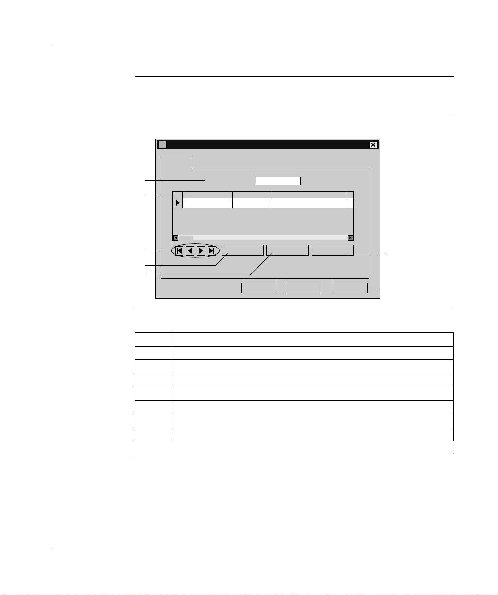
Illustration The screen dedicated to the Uni-Telway driver looks like this:
Uni-Telway Configuration
Station List
1
2
3
Target Station:
Station ID
[Default] COM 1
Remote Password Ph
Add Modify Delete
[Default]
6
4
5
OK
Cancel Apply
7
Description This table describes the different areas which make up the configuration screen:
Number Element
1 This field is used to display the active profile.
2 This list is used to display the driver profile associated with each remote device.
3 These buttons are used to select the driver profile.
4 This button is used to add new profiles to the list.
5 This button is used to modify the profile of the driver selected from the list.
6 This button is used to remove a profile from the list.
7 This button is used to make the profile selected with the cursor active.
20
Serial port
Uni-Telway
parameters
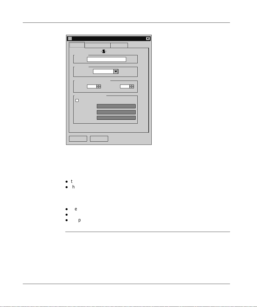
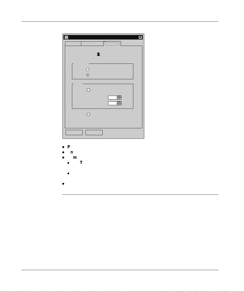
The parameters are presented in the following manner:
Parameters of the Station
Uni-Telway
Link Parameters
Station ID
[Default]
COM Port
Uni-telway Slaves address
Communication Mod em
Hayes
Tel No.
Password
OK
COM 1
13
Modem Used
Cancel
Advanced
NumberBase
The Station ID window is used to name the remote device associated with the
driver configuration.
The COM Port window is used to select the communication port used.
The Uni-telway Slave Address window is used to enter:
l
the standard slave address of the driver,
l
the number of slave addresses used by the driver.
The Modem Communication window is useful when the local station is
communicating via a modem. In this case, this window is used to enter:
l
the HAYES string to be sent to the modem in order to initialize it,
l
the call number of the remote device,
l
the password to be sent t o the re mote devic e, if i t has been c onfig ured w ith a list
of callers with passwords (e.g. TSX MDM 10 card configured with passwords).
21
Serial port
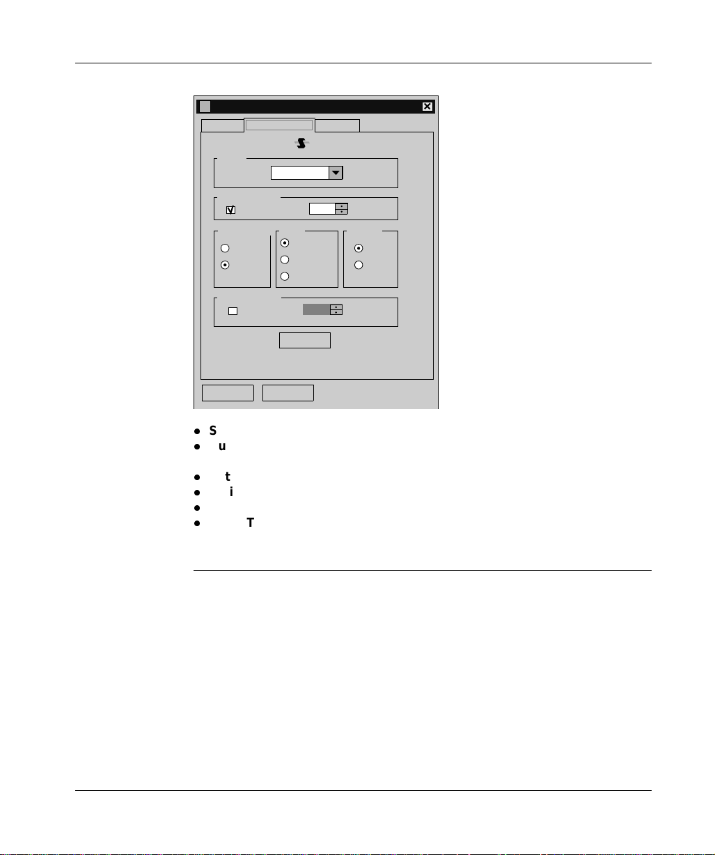
Line parameters The parameters are presented in the following manner:
Parameters of the Station
Uni-Telway
Link Parameters
Speed
Auto-Adaptatio n
Valid
Data Content
7 bits
8 bits
RTS/CTS Delay
Use CTS
OK Cancel
9600 bits/s
Parity
Odd
Even
Without
1
Default
Advanced
1
seconds
Stop Bits
1 bit
2 bits
X 100 ms
This tab is used to configure the parameters linked to transmission:
l
Speed: transmission speed of between 300 and 115 200 bits/s,
l
Auto-Adaptation: self-adaptat ion of s pe ed (t im e du ring w hi ch the driver tries to
connect at a given speed),
l
Data: specifies the size of the data exchanged over the line,
l
Parity: is used to set whether a parity bit is added or not, as well as its type,
l
Stop Bits: is used to enter the number of stop bits used for communication,
l
RTS/CTS Delay: enables the CTS signal to be used in the event of multidrop
communication.
The Default button is used to reset all these parameters to their default value.
22
Serial port
Advanced
parameters
The parameters are presented in the following manner:
Parameters of the Station
Uni-Telway
Link Parameters
Type of li nk
Other
OK Cancel
PC
Uni-Telway
PCL No.
TimeOut Link
RX/TX Delay
Force Virtual Com Port
Advanced
-1
-1
This tab is used to configure the line type:
l
PC: uses the driver to connect to a series 7 PLC terminal port,
l
Uni-Telway: default value, uses the driver to communicate in Uni-Telway,
l
Num PLC: uses the driver to connect to NUM PLCs.
l
RX/TX Delay: by default set to –1; is used to extend the return time (if the
station is too fast).
l
Link Timeout: by default set to –1; is used to set the maximum time for
detecting the right transmission speed.
l
Force Virtual Com Port: must be ch ecked if the Unit-Te lway driver uses a virtual
communication port exce pt for use with the TSXPCX 3030 cable.
23

Serial port
How to configure the driver
At a Glance During driver installation, a default profile is proposed. This profile can be modified
or a new one created.
How to create a
new profile
From the driver configuration screen.
Step Action
1 Click on the Add... button. see Uni-Telway parameters, p. 21.
2 Enter station name.
3 Select COM port.
4 Define the driver slave address.
5 If the driver uses a modem to communicate, select the Use modem box and
enter the different fields associated with it.
6 Select the Line parameters (See Line parameters, p. 22) tab.
7 Configure the transmission parameters according to the remote device (baud
rate, parity, data bits, etc.).
8 If the driver requires specific configuration, click on the Advanced (See
Advanced parameters, p. 23) tab and configure the parameters according to the
remote device.
9 Accept the configuration by clicking on Ok.
Result: the new configuration appears in the list.
24

Serial port
How to modify a
profile
How to remove a
profile
From the driver configuration screen.
Step Action
1 Select a configuration profile from the list.
Result: the cursor moves to the selected line.
2 Click on the Modifier button; see Uni-Telway parameters, p. 21.
3 Modify the parameters according to the remote device.
4 Select the Line parameters (See Line parameters, p. 22) tab and modify the
transmission parameters according to the remote device (speed, parity, data,
etc.).
5 If the driver requires specific configuration, click on the Advanced (See
Advanced parameters, p. 23) tab and modify the parameters according to the
remote device.
6 Accept the configuration by clicking on Ok .
Result: the new configuration appears in the list.
From the driver configuration screen.
Step Action
1 Select a configuration profile from the list.
Result: the cursor moves to the selected line.
2 Click on Delete.
3 Press the Yes button to confirm your choice.
Result: the configuration is removed from the list.
How to activate a
profile
25
From the driver configuration screen.
Step Action
1 Select a profile from the list.
Result: the cursor moves to the selected line.
2 Click on the Apply button.

Serial port
26
At a Glance
TSX SCP 114 card
3
Subject of this
Section
What’s in this
Chapter?
This chapter describes instal lation of the Uni -Tel way driv er commu nicat ing in s lave
mode via the PCMCIA TSX SCP 114 card with a remote device.
Driver installation consists of three steps:
l
installation of files on the station,
l
configuration of the driver
l
configuration of the operating system to recognize the driver.
This chapter contains the following topics:
Topic Page
How to install the driver 28
Driver configuration screens 30
Configuration of the Windows 98 operating system 32
Configuration of the Windows 2000\XP operating system 33
Configuration of Win NT operating system 34
27

TSX SCP 114 card
How to install the driver
At a Glance Driver installation is a standard installation. It can be launched either:
l
from the drivers’ CD-ROM,
l
or from disks if the station has no CD-ROM drive.
Note: The installation disks are created from the CD-ROM.
How to create a
set of disks
Use the following procedure to create installation disks:
Step Action
1 Use a station which has a CD-ROM drive.
2 Insert the CD-ROM into the drive.
3 Access the directory of the driver to be copied onto disk.
4 Copy the contents of the DISK1 directory onto a disk. Repeat this step for each
DISK directory.
Note: it is advisable to number the disks.
28
TSX SCP 114 card
How to install the
To install the driver, carry out the following procedure:
driver
Start of installation
Installation by
CD-ROM?
Yes
Insert CD-ROM in CD-ROM drive
Appearance
of the file
INSTALL.HTM
?
Yes
Click on the link which corresponds
to the driver to be installed
Choose Run this program from
its current location then confirm
by clicking on OK
No
No
Access the directory of the driver
to be installed corresponding to
the PC’s operating system
Access the directory DISK1
Double click on the file
SETUP.EXE
Insert the 1st disk in the drive
Choose Yes in the security warning
29
screen
Click on Next
Configure the driver then close the
configuration screen
Restart the computer
End of installation
TSX SCP 114 card
Driver configuration screens
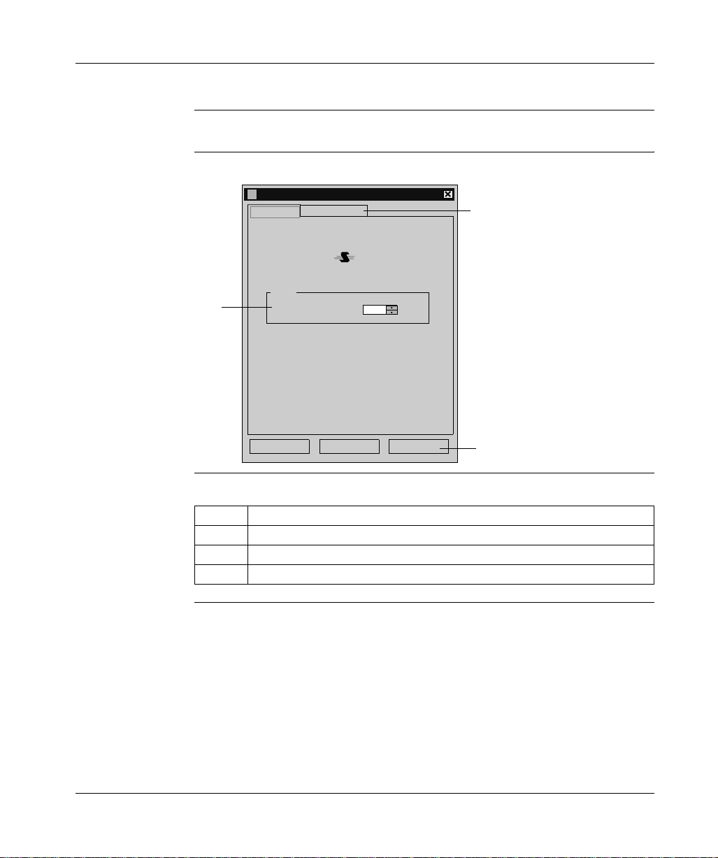
At a Glance The configuration too l is used to configu re the TSX S CP 114 card Uni-Telway driver.
Illustration The screen dedicated to the Uni-Telway driver looks like this:
TSX SCP114 Configuration
Uni-Telway
1
Link Parameters
Slave
Slave number (Ad0 )
1
3
OK Cancel
Apply
2
Description This table describes the different areas which make up the configuration screen:
Number Element
1 This window is used to set the standard slave address (Ad0) used by the card.
2 This button is used to recognize the address.
3 This tab is used to access the configuration of transmission parameters.
30

Line para meters The parameters are presented in the following manner:
Station Parameters
Uni-Telway
Link Parameters
Speed
9600 bits/s
TSX SCP 114 card
Delay
Default
Data Content
7 bits
8 bits
RTS/CTS Delay
1
Cancel
OK Cancel
10
ms
Parity Stop Bits
Even
Odd
Without
X 100 ms
Default
1 bit
2 bits
Apply
This tab is used to configure the parameters linked to transmission:
l
transmission speed of between 300 and 19,200 bits/s,
l
Time-out,
l
Number of data bits: specifies the size of the data exchanged over the line,
l
parity: is used to set whether a parity bit is added or not, as well as its type,
l
number of Stop bits: is used to enter the number of stop bits used for
communication,
l
RTS/CTS delay: enables the CTS signal to be used in the event of multidrop
communication.
The Default button is used to reset all these parameters to their default value.
31

TSX SCP 114 card
Configuration of the Windows 98 operating system
At a Glance After the driver installation and configuration phase, the operating system shall
recognize the TSX SCP 114 card and its driver.
Note: So that the dri ve r i s l oad ed whe n th e c ard is i ns erte d, i t i s es sen tia l that the
station is restarted t o update the registry.
How to configure
the operating
system
The following procedure describes how to configure the operating system:
Step Action
1 Install and configure the driver.
2 Restart the station.
3 Insert the PCMCIA card into its slot.
Result:
The system automatically detects the card and the following window is
displayed:
New device detected
Telemecanique-TSX SCP 114
Select which driver you want to install for your new hardware
Windows default driver
Driver supplied on hardware manufacturer d
D
o not install a driver (Windows will not prompt you again)
elect from list of drivers
S
OK
iskette
Cancel Help
4 Select the option Windows default driver.
5 Confirm using the Ok button.
?
32

TSX SCP 114 card
Configuration of the Windows 2000\XP operating system
At a Glance After the driver installation and configuration phase, the operating system shall
recognize the TSX SCP 114 card and its driver.
Note: When configuring the system, it is not necessary to restart the station.
How to configure
the operating
system
The following procedure describes how to configure the operating system:
Step Action
1 Install and configure the driver.
2 Insert the PCMCIA card into its slot.
Result:
The system automatically detects the card and loads the card driver.
33

TSX SCP 114 card
Configuration of Win NT operating system
At a Glance After the driver installation and configuration phase, the operating system shall
recognize the TSX SCP 114 card and its driver.
Note: So that the dri ve r i s l oad ed whe n th e c ard is i ns erte d, i t i s es sen tia l that the
station is restarted t o update the registry.
How to configure
the operating
system
Case in which
the driver does
not start
The following procedure describes how to configure the operating system:
Step Action
1 Install and configure the driver.
2 Shutdown your machine.
3 Insert the PCMCIA card into its slot.
Result:
The system automatically detects the card and loads the driver.
One possibility is that th e default IRQ3 is busy, in which case another one mu st be
used:
Follow the steps below to detect an available IRQ:
Step Action
1 In the taskbar, select "Start ->Run".
2 enter the command "Winmsd"
3 Select the tab "Resources", choose an available IRQ and confirm with OK.
4 Edit the DSCP114.REG file and modify the value of "InterruptNumber"
5 In the taskbar, select "Start ->Run", enter the command "DSCP114" and
confirm.
6 Restart your machine.
34

At a Glance
FIP drivers
III
Subject of this
Part
What’s in this
Part?
This part describe s how to in stall the drive rs asso ciated w ith FIP co mmunic ation for
Windows 98, Windows 2000\XP and Windows NT operating systems.
This part contains the following chapters:
Chapter Chapter Name Page
4 TSX FPP 20 card 37
5 TSX FPC 10 ISA card 45
35

FIP drivers
36

At a Glance
TSX FPP 20 card
4
Subject of this
Chapter
What’s in this
Chapter?
This chapter describe s installation of the driver us ed to communicate in Fipway\Fi pio
mode via the TSX FPP K200 connection kit with a remote device.
Driver installation consists of three steps:
l
installation of files on the station,
l
configuration of the driver,
l
configuration of the operating system to recognize the driver.
This chapter contains the following topics:
Topic Page
How to install the driver 38
How to install the driver 40
Configuration of the Windows 98 operating system 41
Configuration of the Windows 2000\XP operating system 42
Configuration of the Windows NT operating system 43
37

TSX FPP 20 card
How to install the driver
At a Glance Driver installation is a standard installation. It can be launched either:
l
from the drivers’ CD-ROM,
l
or from disks if the station has no CD-ROM drive.
Note: The installation disks are created from the CD-ROM.
How to create a
set of disks
Use the following procedure to create installation disks:
Step Action
1 Use a station which has a CD-ROM drive.
2 Insert the CD-ROM into the drive.
3 Access the directory of the driver to be copied onto disk.
4 Copy the contents of the DISK1 directory onto a disk. Repeat this step for each
DISK directory.
Note: it is advisable to number the disks.
38

TSX FPP 20 card
How to install the
To install the driver, carry out the following procedure:
driver
Start of installation
Installation by
CD-ROM?
Yes
Insert CD-ROM in CD-ROM drive
Appearance
of the file
INSTALL.HTM
?
Yes
Click on the link which corresponds
to the driver to be installed
Choose Run this program from
its current location then confirm
by clicking on OK
No
No
Access the directory of the driver
to be installed corresponding to
the PC’s operating system
Access the directory DISK1
Double click on the file
SETUP.EXE
Insert the 1st disk in the drive
Choose Yes in the security warning
39
screen
Click on Next
Configure the driver then close the
configuration screen
Restart the computer
End of installation

TSX FPP 20 card
How to install the driver
At a Glance The configuration too l is used to c onfigure th e driver in Fipway or F ipio mode to use
the TSX FPP 20 card.
Illustration The screen dedicated to the card driver looks like this:
TSXFPP20 Configuration
Network Parameters
Fipway
Fipio
Network :
Station :
0
63
Fipway (World FIP)
Fipio (WORLD FI P )
Appliquer
1
2
3
Network Type
OK Annuler
Description This table describes the different areas which make up the configuration screen:
Number Element
1 This field is used to set the network address.
2 This field is used to set the station address.
3 This window is used to select the type of Fipway or Fipio connection.
40

TSX FPP 20 card
Configuration of the Windows 98 operating system
At a Glance After the driver installation and configuration phase, the operating system shall
recognize the TSX FPP 20 card and its driver.
Note: So that the driver loads up when the card is inserted, it is essential that the
station is restarted to allow Windows to update the registry.
How to configure
the operating
system
The following procedure describes how to configure the operating system:
Step Action
1 Install and configure the driver.
2 Restart the station.
3 Insert the PCMCIA card into its slot.
Result:
The system automatically detects the card and the following window is
displayed:
New device detected
Telemecanique-TSX SCP 114
Select which driver you want to install for your new hardware
Windows default driver
Driver supplied on hardware manufacturer d
D
o not install a driver (Windows will not prompt you again)
elect from list of drivers
S
OK
iskette
Cancel Help
4 Select the option Windows default driver.
5 Confirm using the Ok button.
?
41

TSX FPP 20 card
Configuration of the Windows 2000\XP operating system
At a Glance After the driver installation and configuration phase, the operating system shall
recognize the TSX FPP 20 card and its driver.
Note: When configuring the system, it is not necessary to restart the station.
How to configure
the operating
system
The following procedure describes how to configure the operating system:
Step Action
1 Install and configure the driver.
2 Insert the PCMCIA card into its slot.
Result:
The system automatically detects the card and loads the card driver.
42

TSX FPP 20 card
Configuration of the Windows NT operating system
At a Glance After the driver installation and configuration phase, the operating system shall
recognize the TSX FPP 20 card and its driver.
Note: When configuring the system, it is not necessary to restart the station.
How to configure
the operating
system
Case in which
the driver does
not start
The following procedure describes how to configure the operating system:
Step Action
1 Install and configure the driver.
2 Shutdown your machine.
3 Insert the PCMCIA card into its slot.
Result:
The system automatically detects the card and loads the driver.
One possibility is that the defa ult IRQ3 is busy, in which ca se another one must be
used:
Follow the steps below to detect an available IRQ:
Step Action
1 In the taskbar, select "Start ->Run".
2 enter the command "Winmsd"
3 Select the tab "Resources", choose an available IRQ and confirm with OK.
4 Edit the DSCP114.REG file and modify the value of "InterruptNumber"
5 In the taskbar, select "Start ->Run", enter the command "DFPP20" and
confirm.
6 Restart your mac hine.
43

TSX FPP 20 card
44

At a Glance
TSX FPC 10 ISA card
5
Subject of this
Chapter
What’s in this
Chapter?
This chapter describes installation of the driver communicating in Fipway/Fipio
mode via the ISA TSX FPC 10 card and a remote device.
Driver installation consists of three steps:
l
installation of files on the station,
l
configuration of the driver,
l
configuration of the operating system to recognize the driver.
This chapter contains the following topics:
Topic Page
How to install the driver 46
Driver configuration screen for Windows NT 48
Driver configuration screen for Windows 98\2000\XP 50
Configuration of the operating system using the TSX FPC 10 card 51
How to select the hardware type for Windows 98 52
How to select the hardware type for Windows 2000\XP 55
How to configure hardware parameters for Windows 98 58
How to configure hardware parameters for Windows 2000\XP 60
How to adjust the ISA TSX FPC 10 card parameters 63
45

TSX FPC 10 ISA card
How to install the driver
At a Glance Driver installation is a standard installation. It can be launched either:
l
from the drivers’ CD-ROM,
l
or from disks if the station has no CD-ROM drive.
Note: The installation disks are created from the CD-ROM.
How to create a
set of disks
Preliminary
operations
Use the following procedure to create installation disks:
Step Action
1 Use a station which has a CD-ROM drive.
2 Insert the CD-ROM into the drive.
3 Access the directory of the driver to be copied onto disk.
4 Copy the contents of the DISK1 directory onto a disk. Repeat this step for each
DISK directory.
Note: it is advisable to number the disks.
Before installing the new dr iver, you mu st check that th ere is no previous ve rsion on
the station.
If a driver does exist, you must delete it before carrying out the new installation.
The previous version of the driver can be uninstalled using:
l
Drivers Manager software,
l
or the Control Panel → Add/Remove Programs.
46

TSX FPC 10 ISA card
How to install the
To install the driver, carry out the following procedure:
driver
Start of installation
Installation by
CD-ROM?
Yes
Insert CD-ROM in CD-ROM drive
Appearance
of the file
INSTALL.HTM
?
Yes
Click on the link which corresponds
to the driver to be installed
Choose Run this program from
its current location then confirm
by clicking on OK
No
No
Access the directory of the driver
to be installed corresponding to
the PC’s operating system
Access the directory DISK1
Double click on the file
SETUP.EXE
Insert the 1st disk in the drive
Choose Yes in the security warning
47
screen
Click on Next
Configure the driver then close the
configuration screen
Restart the computer
End of installation

TSX FPC 10 ISA card
Driver configuration screen for Windows NT
At a Glance The configuration too l is used to c onfigure th e driver in Fipway or F ipio mode to use
a ISA TSX FPC 10 card.
Illustration The screen dedicated to the card driver looks like this:
FP
FP
Dfpway - Configuration FIP FPC SN
Fipway address
Fipway mode
Network
Station
0
31
Driver instance
FIP01
FIP02
Save
Read
By default
Fipio address
Fipio Mode
Fipio connection point
0
Description This table describ es the different area s and buttons wh ich make up the conf iguration
screen:
Zone Description
Fipway address This area is used to define the network address of the station when the
driver is configured in Fipway mode.
Fipio address This area is used to define the connection point number when the driver
is configured in Fipio mode.
Driver instance This area is used to select the instance of the driver used (max. 2).
Save Used to save the configuration of the driver that has just been entered.
Read Used to read the configuration of the driver saved previously.
By default Allows default automatic entry of the driver configuration.
48

TSX FPC 10 ISA card
Advanced
configuration
To access the advanced configuration screen use the commands
"File->Advanced Configuration " .
The following window is displayed:
Configuration FIP FPC SN - Advanced
I/O address
DMA channel
210h
Channel 5
Channel 6
Channel 7
Interrupt
IRQ 3
IRQ 5
IRQ 10
IRQ 11
IRQ 15
Mode
On
Off
PRUC
OK
Cancel
By default
0
World FIP
The following table describes the different areas and buttons in the window.
Zone Description
I/O address Used to choose the address in the storage area with which the driver
can find the Fipway FPC10 module. This address must be included
between 100h and 3F0h and be identical to the address configured in
the module.
DMA channel Used to select the DMA resource shared by the driver and the module.
This information must be identical to that configured on the module.
Interrupt Used to select the interrupt shared by the driver and the communication
module. This information must be identical to that configured on the
module.
Mode Used to disable the driver by checking the "OFF" box. T his is usually the
case for the second instance of the driver. (FIP02).
WorldFip Allows use of frames in WorldFip profile A format whose CRC
calculation complies with the IECSC65C105 standard.
Cancel button Used to return to the previous window.
By default button Used to configure the different areas with default parameters.
OK button Used to acknowledge the new configuration parameters.
49

TSX FPC 10 ISA card
Driver configuration screen for Windows 98\2000\XP
At a Glance The configuration too l is used to c onfigure th e driver in Fipway or F ipio mode to use
a ISA TSX FPC 10 card.
Illustration The screen dedicated to the card driver looks like this:
TSXFPPC10 Configuration
Network Parameters
Fipway
Fipio
Network:
Station:
0
63
Fipway (World FIP)
Fipio (WORLD FI P )
Apply
1
2
3
Network Type
OK Cancel
Description This table describes the different areas which make up the configuration screen:
Number Element
1 This field is used to set the network address.
2 This field is used to set the station address.
3 This window is used to select the type of Fipway or Fipio connection.
50

TSX FPC 10 ISA card
Configuration of the operating system using the TSX FPC 10 card
At a Glance After the driver installation and configuration phase, the operating system shall
recognize the ISA TSX FPC 10 card and its driver.
Installation
principles
As this card is not automatically recognized by the operating system, the following
phases must be carried out :
Step Action
1 Select the hardware type:
l
for Win 98 see How to select the hardware type for Windows 98, p. 52,
l
for Win 2000/XP see How to select the hardware type for Windows 2000\XP,
p. 55,
l
for Win NT no operation is required.
2 Configure the parameters of the operating system to recognize the card:
l
for Win 98 see How to configure hardware parameters for Windows 98,
p. 58,
l
for Win 2000/XP see How to configure hardware parameters for Windows
2000\XP, p. 60,
l
for Win NT no operation is required.
3 Switch off the PC.
4 Adjust the card parameters (See How to adjust the ISA TSX FPC 10 card
parameters, p. 63):
l
the standard I/O address,
l
the IRQ interrupt address.
5 Connect the card to the ISA bus.
6 Turn the PC back on.
Result: the driver is operational.
51

TSX FPC 10 ISA card
How to select the hardware type for Windows 98
Procedure After having installed and configured t he driver, c arry out the following p rocedur e to
select the hardware type.
Step Action
1 In the initial window which is displayed, click on Next.
Result
The following window appears:
Add new hardware Assistant
Windows can now search for hardware that is
incompatible with Plug-and-Play, or you can select the
hardware from a list.
When Windows de t ect s a ne w har d war e, i t aut om atic all y
determines the current parameters for the periphera l and
correctly installs the pilot. It is therefore strongly
recommended tha t yo u a ll ow Wind ow s to de t ect the new
hardware.
Do you wish for Windows to automatically detect any
new hardware?
es (recommended )
Y
o, I wish to select the hardware from a list.
N
?
52
< Previous:
Next>
Cancel
TSX FPC 10 ISA card
Step Action
2Answer No to the question Do you want Windows to search for your new
hardware?
Result
The following window appears:
Add new hardware Assistant
Select the hardware type you wish to install.
ypes of hardware :
T
Modem
Mouse
Multifunction adapter cards
Network cards
Other peripher als
?
?
?
PCMCIA extension
FPC10 Device
Ports (COM & LPT)
Printer
SCSI Controllers
< Previous:
Next>
Cancel
3 Select FPC10 Device from the list then click on Next.
4 Select FPC10 WDM Device from the list then click on Next.
Result
The operating system suggests the hardware parameters that you must adjust
on the card.
Add new hardware Assistant
Windows can install your hardware using the following parameters:
Warning: your hardware cannot be configured for use with the resources
listed. You may use the Peripherals Manager to adjust the parameters before
restarting your computer . Click successively on the Start, Parameters,
Control panel, System, and Peripherals Manager tabs. To modify the
hardware parameters, consult the hardware document at ion supplied.
To continue installing the software needed by your hardware, click N ext .
Type of resource Parameter
Input/output range 0190-019F
Interrupt Request (IRQ) 10
< Previous:
53
Next> Cancel
Print...

TSX FPC 10 ISA card
Step Action
5 Click on Next.
6Answer No to the question Do you want to restart your computer now?
Result
The following window appears and the card is shown in the station’s hardware
configuration.
System Properties
General
Peripherals Manager Hardware Profiles
Display peripherals by t
Computer
+
CD-ROM
+
Disk drives
+
Graphics cards
+
Disk controllers
Hard disk controllers
+
Keyboard
+
+
Screens
Mouse
+
+
Network cards
FPC10 Device
-
FPC10 WDM Device
!
Ports (COM & LPT)
+
Sound, video and game controllers
+
System peripherals
+
USB bus controllers
+
ype
Performance
Disp
lay peripherals by connection
?
54
Properties: Refresh Delete Print...
7 Do you want to modify the parameters?
l
If yes, go to the procedure: how to modify hardware parameters (See How
to configure hardware parameters for Windows 98, p. 58),
l
If no, click on Ok then restart the station with the card.
CancelOK

TSX FPC 10 ISA card
How to select the hardware type for Windows 2000\XP
Procedure After having installed an d configu red the driv er, carry out the followin g procedure to
select the hardware type.
Step Action
1 In the initial window which is displayed, click on Next.
Result
The following window appears:
Add/Delete new hardware Assistant
Select a task for the hardware
What task do you wish to perform on the hardwa re?
Select the task you wish to perform for your hardware, the n click on next.
Add/Troubleshoot a peripheral
Choose this option to add a new peripheral to your computer or if you have difficulty
operating an ex isting peripheral.
Uninstall/D i s connect a peripher al
Choose this option to uninstall a peripheral or to prepare your computer for the
disconnection of a peripheral .
CancelNext>< Previous
55

TSX FPC 10 ISA card
Step Action
2 Select the option Add/Troubleshoot a peripheral then click Next.
Result
The following window appears:
Add/Delete new hardware Assistant
Selecting a hardware peripheral
What hardware peripheral do you wish to troubl eshoot?
The followin g hardware is already installed on your compu ter. If you encounter
difficulty with one of these peripherals, select the peripheral and click Next.
If you try to add a pe r ipheral and it doesn’t appear below,
select Add a new per i pheral, then click Next.
Peripherals
Add a new periphe r al
COMPAQ 171 FS
Disk drive
COMPAQ CRD-8320B
WDC AC36400L
ES1869 Control Interface (WDM)
ES1869 Plug an d Pl a y Audio Drive (WDM)
CancelNext>< Previous
3 Select the option Add a new peripheral then click Next.
4Answer No to the question Do you want Windows to search for your new
hardware?
56
Step Action
5 Click on Next.
Result
The following window appears:
Add/Delete new hardware Assistant
Hardware type
TSX FPC 10 ISA card
Which hardware type do you wish to install?
Select the hardware type you wish to install.
Hardware types:
PCX57 Device
Port (COM & LPT)
Printers
SCSI and RAID controllers
Sound, video and game controllers
Systems peripherals
Tape drives
FPC10 Device
< Previou s
CancelNext >
6 Select FPC10 Device from the list then click on Next.
7 Select FPC10 WDM Device from the list then click on Next.
Result: an information window appears.
8 A window informs the user that the hardware parameters of the card must be
entered by the user. Click on OK and go to the next procedure: how to
configure hardware parameters (See How to configure hardware parameters
for Windows 2000\XP, p. 60).
57

TSX FPC 10 ISA card
How to configure hardware parameters for Windows 98
Procedure When you want to modify the hardware parameters, carry out the following
procedure.
Step Action
1 Click on Properties.
Result
The following window appears:
Properties of the peripheral PCX57 WDM
General Pilot
Parameters based on:
Type of reso ur ce Parameter
Interrupt Request (IRQ) 10
Modify the parameters...
List of peripher al in conflict:
No conflict.
Resources
Peripheral PCX57 WDM
se automatic paramete r s
U
Standard config ur ation 0
Input/output ran ge 01A0-001AF
?
58
OK Cancel
2 Uncheck the box Use automatic settings.
3 Select Input/Output Range from the list.

Step Action
4 Click on Change settings.
Result
The following window appears:
TSX FPC 10 ISA card
Modify input/output range
Enter the input/output range you wish to define for this
peripheral.
You c an either enter a s pecific range a nd the closest val i d
range will be automatically selected, or select a range using
the indicator arro ws .
V
alue:
01A0-01AF
Information concerning conflicts
The parameter you have chosen is not in conflict with
other peripherals.
No peripherals in conflict.
OK Cancel
?
5 From the Value list, select the non-conflicting address range.
Note: note the values because they must be coded onto the ISA card.
6 Confirm with OK.
7 Carry out steps 5 to 8 selecting Interrupt Request from the list.
8 Confirm with Ok then restart the station with the card connected.
59

TSX FPC 10 ISA card
How to configure hardware parameters for Windows 2000\XP
Procedure After having selected the hardware type, carry out the following procedure to
configure the parameters.
Step Action
1 Click on the Resources button.
2 Click on Manual Configuration.
Result
The following window appears:
Add new hardware Assistant Properties
Resources
FPC10 WDM Device
"
"
Resource parameters:
Type of Resource Parameter
Input/output range ?
Interrupt Request (IRQ) ?
?
60
Parameters based on:
List of peripherals in conflict:
No conflict.
3 Uncheck the box Use automatic settings.
4 Select Input/Output Range from the list.
Standard configuration 0000
Use the automatic parameters
Modify the parameters...
OK
Cancel

Step Action
5 Click on Change settings.
Result
The following window appears:
Modify input/output range
Enter the input/output range y ou wish to define for this
peripheral.
You can either enter a specific range and the closest valid range
will be automatically selected, or select a range using the upper or
lower indicator arrows.
This resource is assigned to the following child peripherals:
0210-021F
Value:
Information concerning conflicts
The parameter yo u ha v e chosen is not in conflict wi th other
peripherals.
No peripherals in conflict
OK Cancel
?
6 From the Value list, select the non-conflicting address range.
TSX FPC 10 ISA card
Note: note the values because they must be coded onto the ISA card.
7 Confirm with OK.
Result: a confirmation window appears.
8 Confirm with Yes.
9 Carry out steps 4 to 8 selecting Interrupt Request from the list.
61

TSX FPC 10 ISA card
Step Action
10 Accept the configuration with OK.
Result
The following window appears:
Add / Remove Ha rdware Wizard
End of Add/Delete hardware Assistant
The following hardware has been installed:
FPC10 WDM Device
Check the docum enta tion of your ha rdwar e to kn ow wheth er
you should conf igure the new hardw ar e manually. To
operate the hardware you must re start the computer.
To display or modify the resources for this
peripheral, click Resources.
To close the Assistant, click on Finish.
11 Click on Finish to confirm hardware configuration.
Resources
Cancel Finish<Back
62

TSX FPC 10 ISA card
How to adjust the ISA TSX FPC 10 card parameters
At a Glance Before installing the TSX FPC 10 card, you must adjust the following parameters:
l
the standard I/O address,
l
the IRQ interrupt address.
Illustration This card comprises the following elements:
12 3
Numbers and
elements
63
The following table describes the different parameters to be adjusted:
Number Element
1 Jumper s (SW1) are used to select the DMA channel (Direct Acc ess Mem ory)
(no object).
2 A jumper (SW2) is used to select the IRQ (Interrupt Request) level.
3 The micro-switches (SW3) are used to select the standard address of the card
in the I/O space.

TSX FPC 10 ISA card
Procedure To adjust the parameters, proceed in the following manner:
Step Action
1 Set the IRQ interrupt jumper to comply with the address provided by the windows
98 (See How to configure hardware parameters for Windows 98, p. 58) or
2000/XP (See How to configure hardware parameters for Windows 2000\XP,
p. 60) operating systems.
2 Code the standard I/O address provided by the operating system windows 98
(See How to configure hardware parameters for Windows 98, p. 58) or 2000/XP
(See How to configure hardware parameters for Windows 2000\XP, p. 60) with
the micro-switches.
Example of IRQ
selection
Example of
standard
address
selection
The interrupt address provided by the system is 10:
15
IRQ
11
10
3
5
Note: The jumper must not be set in the IRQ position.
The standard address provided by the system is equal to 210 in hexadecimal:
200
10080402010
ON
12345678
64

At a Glance
ETHWAY driver
IV
Subject of this
Part
What’s in this
Part?
This part describes how to install the drivers associated with ETHWAY
communication for Windows 2000\XP and Windows NT operating systems.
This part contains the following chapters:
Chapter Chapter Name Page
6 Installation 67
65

ETHWAY driver
66

At a Glance
Installation
6
Subject of this
Chapter
What’s in this
Chapter?
This driver is used to communicate via an Ethernet card using the ETHWAY
protocol. Driver installation consists of two main steps:
l
installation of files on the station,
l
configuration of the driver.
This chapter contains the following topics:
Topic Page
How to install the driver for Windows 2000\XP 68
How to install the driver for Windows NT 71
Driver configuration tool 73
67

Installation
How to install the driver for Windows 2000\XP
At a Glance The ETHWAY protocol is installed from:
l
from the drivers’ CD-ROM,
l
or from disks if the station has no CD-ROM drive.
Note: The installation disks are created from the CD-ROM.
How to create a
set of disks
Use the following procedure to create installation disks:
Step Action
1 Use a station which has a CD-ROM drive.
2 Insert the CD-ROM into the drive.
3 Access the directory of the driver to be copied onto disk.
4 Copy the contents of the DISK1 directory onto a disk. Repeat step for each
DISK directory.
Note: it is advisable to number the disks.
68

Installation
How to install the
driver
The ETHWAY driver is installed in accordance with the following procedure:
Step Action
1 Insert the CD-ROM or the first disk.
2 Access the Control Panel in Windows.
3 Double-click on the Network connections and Remote access icon.
4 Select the icon Local connection then by right-clicking select the command
Properties.
Result
The following window appears:
Local Area Connection Properties
General
Connect using:
3Com EtherLink XL PCI C omb o NIC (3 C9 00B -CO MBO)
The selected components are used by this connec tion:
Client for Microsoft Networks
File and printer Sharing for Microsoft Networks
Internet Protocol (TCP/IP)
Install...
Description
Enables you to access the resources on a Microsoft
network.
Uninstall
Properties
?
Configure
Display an icon in the Task bar once connected
OK Cancel
5 Click on the Install button.
69

Installation
Step Action
6 In the Select Network Component Type window, select the type Protocol
then click on Add.
Result
The following window appears:
Selection of network protocol
Click on the network protocol yo u wish to install and then click on OK.
If you have an installation disk for this component, click on the Disk
supplied.
Manufacturers:
Microsoft
Schneider Corporation
Network protocol:
Network supervisor pilot
DLC Protocol
NetBEUI Protocol
Transport Protocol compatible with NWLi nk
IPX/OSI-LAN Protocol
Disk supplied...
OK Cancel
7 Click on Have Disk.
8 Select the access path of the files to be installed from the CD-ROM or the disk
using the Browse button.
9 Click on Ok.
10 In this window select the ETHWAY Protocol then click on OK.
11 Select the ETHWAY protocol then click on Properties.
12 In the configuration screen (See Driver configuration tool, p. 73), configure the
protocol then click on OK.
13 Complete the installation by clicking on OK.
70

How to install the driver for Windows NT
At a Glance The ETHWAY protocol is installed from:
l
from the drivers’ CD-ROM,
l
or from disks if the station has no CD-ROM drive.
Note: The installation disks are created from the CD-ROM.
Installation
How to create a
set of disks
Use the following procedure to create installation disks:
Step Action
1 Use a station which has a CD-ROM drive.
2 Insert the CD-ROM into the drive.
3 Access the directory of the driver to be copied onto disk.
4 Copy the contents of the DISK1 directory onto a disk. Repeat step for each
DISK directory.
Note: it is advisable to number the disks.
71

Installation
How to install the
driver
The ETHWAY driver is installed in accordance with the following procedure:
Step Action
1 Insert the CD-ROM or the first disk.
2 Access the Control Panel in Windows.
3 Launch the Networks icon.
4 Select the Protocols tab and click on Add.
5 In the protocol selection window click on Have Disk...
6 Confirm your choice of diskette or CD-ROM and then choose ETHWAY
Protocol. The driver files are copied onto the PC.
7 Select the Links tab and check the link of the ETHWAY protocol with the
Ethernet card(s) installed on the PC. ETHWAY can be linked selectively to 1 or
2 Ethernet cards.
8 Return to the Protocols tab, select ETHWAY Protocoland click on Properties.
9 Enter the ETHWAY Network-Station address in the Network and Station fields.
If 2 Ethernet cards are installed on the PC, repeat this operation for each entry
in the Adapter name list.
10 Confirm the ETHWAY parameters, the network window, then restart the
machine.
72

Installation
2
3
4
5
6
Driver configuration tool
At a Glance The configuration tool is used to configure the Ethernet card to communicate
according to the ETHWAY protocol.
Illustration The card configuration screen looks like this:
ETHWAY Protocol Properties
ETHWAY -Parameters
Adapter Name
1
el3c5891
Export Name
ETHWAY01
Network
0
TE MAC Address
Acknowledgement (ms)
Retry Period Filter Period
800
Buffers
Send
50
Receive
20
Station
63
3000
Size
128
512
?
256
1024
Default
73

Installation
Description This table describes the different areas which make up the configuration screen:
Number Element
1 This field is used to select the Ethernet card (useful if there are several Ethernet
cards). This field cannot be modified under Windows 2000\XP.
2 This field is used to select the ETHWAY driver instance. This field cannot be
modified under Windows 2000\XP.
3 These windows are used to define the address {Network.Station} of the Ethernet
card used.
4 This box is used to replace the Ethernet card’s MAC address with the
SCHNEIDER MAC address (00 80 F4 Network Station).
5 This window is used to configure the reception acknowledgment by defining:
l
the retransmission period between two frames if the remote device is not
responding,
l
the storage time of a frame originating from the remote device (useful for
loaded networks).
Note: in general, storage time is three times the retransmission period.
6 This window is used to configure the transmission and reception buffer size in
bytes.
74

At a Glance
XIP driver on TCP/IP
V
Subject of this
Part
What’s in this
Part?
This part describ es how to instal l the dri vers associat ed with X-Way com munica tion
on TCP/IP for Windows 98, Windows 2000\XP and Windows NT operati ng systems.
Note: The installation of this driver is the same on all operating systems installed.
This part contains the following chapters:
Chapter Chapter Name Page
7 Installation 77
75

XIP driver on TCP/IP
76

At a Glance
Installation
7
Subject of this
Chapter
What’s in this
Chapter?
This driver is used to communicate via an Ethernet card using the X-Way protocol
on TCP/IP.
This chapter describes driver installation, which consists of two steps:
l
installation of files on the station,
l
configuration of the driver.
This chapter contains the following topics:
Topic Page
How to install the driver 78
Driver configuration screen 80
How to configure the driver 82
77

Installation
How to install the driver
At a Glance Driver installation is a standard installation. It can be launched either:
l
from the drivers’ CD-ROM,
l
or from disks if the station has no CD-ROM drive.
Note: The installation disks are created from the CD-ROM.
How to create a
set of disks
Use the following procedure to create installation disks:
Step Action
1 Use a station which has a CD-ROM drive.
2 Insert the CD-ROM into the drive.
3 Access the directory of the driver to be copied onto disk.
4 Copy the contents of the DISK1 directory onto a disk. Repeat this step for each
DISK directory.
Note: it is advisable to number the disks.
78

Installation
How to install the
To install the driver, carry out the following procedure:
driver
Start of installation
Installation by
CD-ROM?
Yes
Insert CD-ROM in CD-ROM drive
Appearance
of the file
INSTALL.HTM
?
Yes
Click on the link which corresponds
to the driver to be installed
Choose Run this program from
its current location then confirm
by clicking on OK
No
No
Access the directory of the driver
to be installed corresponding to
the PC’s operating system
Access the directory DISK1
Double click on the file
SETUP.EXE
Insert the 1st disk in the drive
Choose Yes in the security warning
79
screen
Click on Next
Configure the driver then close the
configuration screen
Restart the computer
End of installation

Installation
Driver configuration screen
At a Glance The configuration too l is used to l ink a driver co nfiguration pr ofile to a remot e device
that communicates with the station.
Illustration The screen dedicated to the XIP driver looks like this:
1
2
Schneider Automation CNFXIP
onfiguration Xip Test Help
C
Profile Local connection
New connectio n
4
5
7
Installed connections
Ready
XIP01
Station:
station1-2
X-Way address:
IP address:
station1-2 001.002 084.000.001.002
station2-* 002. *
station1-3 001.003
station PLC 000.001 139.160.065.100
1 - 2
84 - 0 - 1 - 2
X-Way address:
Save
1 - 1
DNS
084.000.001.002
084.000.001.003
Add
Update
Delete
Delete all
3
6
80

Installation
Description This table describes the different areas which make up the configuration screen:
Number Element
1 All software functions can be accessed using this menu bar:
l
Configuration : creation or deletion of a profile
l
Xip : start, stop or reinitialize the driver
l
Test : test request transmissions with options
l
Aide : information on the software
2 The profile used by the driver is selected from this list.
3 The X-Way address of the station is configured from this window.
4 The new connections with remote devices associated with the driver are set from
this window.
5 Existing connections with remote devices can be viewed via this list.
6 Connections can be added, removed or redefined with these buttons.
7 This status bar is an operating indicator (driver stopped or started) with a
comment zone.
81

Installation
How to configure the driver
At a Glance During driver installati on, a default confi guration profile is proposed. You are able to
modify this profile or create a new one.
Note: If all the network connections are in use or if there are none on the station,
a profile cannot be created.
How to create a
new profile
How to remove a
profile
From the driver configuration screen,
Step Action
1 Select the menu Configurat ion
Result
The following window appears:
Creation of a new XIP profile
XIP XIP/IP
XIP01
2 From the TCP/IP drop-down menu, select the TCP/IP connection to the
network.
3 Click Ok .
ADAPTER01(139.160.67.39)
→ Create a profile.
OK
Cancel
From the driver configuration screen,
Step Action
1 Select the menu Configurat ion
2 From the drop-down menu, select the profile to be removed.
3 Confirm deletion with Ok .
→ Create a profile.
82

Installation
Example The architecture below des cribes the addressing of sta tions on Ethernet and Fipway
networks:
Access to
stations
Adresse X-Way {1.2}
Adresse IP 84.0.1.2
Station D
Adresse X-Way {2.3}
Adresse IP 84.0.1.2
Adresse X-Way {1.1}
Adresse IP 84.0.1.1
Ethernet (1)
Station B
Station C
Adresse X-Way {2.2}
Adresse IP 84.0.1.2
Fipway (2)
Station A
To directly access all the station s on the Ethernet 1 network from sta tion A, enter the
X-Way address {1.*} and the IP address 84.0.1.1.
In order for station A to be able to acces s s tation B, enter for conne ction the X -Way
address {1.2} and the IP address 84.0.1.2.
In order for station A to be able to acces s st ati on B, en ter th e X-Wa y a ddre ss {2.3}
and the IP address of the bridge 84.0.1.2.
How to add a
connection
83
From the configuration screen,
Step Action
1 In the New connection window, enter:
l
the name of the remote station or bridge,
l
the address of the remote station or bridge,
l
the IP address of the remote station or bridge,
2 Click Add.
3 Click Save.
Note: the configuration is saved for the current profile.

Installation
How to remove a
connection
How to modify a
connection
From the configuration screen,
Step Action
1 In the Connections installed window, select the name of the remote station
to be removed.
2 Click Delete.
3 Click Save.
Note: the configuration is saved for the current profile.
From the configuration screen,
Step Action
1 In the Installed Connections window, select the name of the remote station
to be modified.
2 In the New connection window, modify:
l
the name of the remote station or bridge,
l
the address of the remote station or bridge,
l
the IP address of the remote station or bridge,
3 Click Update.
4 Click Save.
Note: the configuration is saved for the current profile.
XIP Instances Once installed, configure the XIP driver and reboot the computer. All XIP profile
instances are initialized.
For each XIP profile configured a corresponding icon appears in the task bar.
84

At a Glance
Drivers for Atrium Processors
VI
Subject of this
Part
What’s in this
Part?
This part describes how to install the drivers associated with the TPCX 57 and
TSX PCI 57 processors for operating systems.
These drivers are:
l
the ISAWAY driver for the TPCX 57 processors,
l
the PCIWAY driver for the TSX PCI 57 processors.
This part contains the following chapters:
Chapter Chapter Name Page
8 ISAWAY driver for TPCX 57 processors 87
9 PCIWAY driver for TSX PCI 57 ••• processors 111
85

Drivers for Atrium Processors
86

At a Glance
ISAWAY driver for TPCX 57 processors
8
Subject of this
Chapter
What’s in this
Chapter?
This driver makes it possible to use the TPCX 57 processor on the ISA bus.
Driver installation consists of two steps:
l
installation of files on the station,
l
configuration of the operating system so that it is recognized.
This chapter contains the following topics:
Topic Page
How to install the driver 88
Configuration of the ISAWAY driver for Windows NT 90
Configuration of ISAWAY driver for Windows 98\2000\XP 95
Configuration of the operating system 96
How to select the hardware type for Windows 98 97
How to select the hardware type for Windows 2000\XP 100
How to configure hardware parameters for Windows 98 103
How to configure hardware parameters for Windows 2000\XP 105
How to adjust the ISA TPCX 57 card parameters 108
87

ISAWAY driver
How to install the driver
At a Glance Driver installation is a standard installation. It can be launched either:
l
from the drivers’ CD-ROM,
l
or from disks if the station has no CD-ROM drive.
Note: The installation disks are created from the CD-ROM.
How to create a
set of disks
Preliminary
operations
Use the following procedure to create installation disks:
Step Action
1 Use a station which has a CD-ROM drive.
2 Insert the CD-ROM into the drive.
3 Access the directory of the driver to be copied onto disk.
4 Copy the contents of the DISK1 directory onto a disk. Repeat this step for each
DISK directory.
Note: it is advisable to number the disks.
Before installing t he new driver, you m ust c heck th at t here is no p reviou s ve rsion of
Windows NT4 on the station.
If a driver does exist, you must delete it before carrying out the new installation.
A previous version can be uninstalled using:
l
Drivers Manager software,
l
or the Control Panel → Add/Remove Programs.
88

ISAWAY driver
How to install the
To install the driver, carry out the following procedure:
driver
Start of installation
Installation by
CD-ROM?
Yes
Insert CD-ROM in CD-ROM drive
Appearance
of the file
INSTALL.HTM
?
Yes
Click on the link which corresponds
to the driver to be installed
Choose Run this program from
its current location then confirm
by clicking on OK
No
No
Access the directory of the driver
to be installed corresponding to
the PC’s operating system
Access the directory DISK1
Double click on the file
SETUP.EXE
Insert the 1st disk in the drive
Choose Yes in the security warning
89
screen
Click on Next
Configure the driver then close the
configuration screen
Restart the computer
End of installation

ISAWAY driver
Configuration of the ISAWAY driver for Windows NT
Access to the
configuration
tool
The configuration tool can be accessed from the taskbar "Start->Programs->
Schneider Electric->Drivers Manager ".
Select the tab "PCX57 Driver" to display the following window:
Management properties of SCHNEIDE R drivers
DRIVERS Manager U NI T ELWAY Driver SCP114 Driver MODBUS SERIAL Driver
PCX57 Driver FPC10 Driver XIP Driver MODBUS Test XWAY Test
Driver PCX57 ISAWAY V1.4 IE05
Copyright
© 1997-1999 Schneider Automation S.A.
Status driver 1: Non operational
Status driver 2: Non operational
Setting Up
OK
PCX
This window shows information on the version and STATUS of the driver installed.
90

ISAWAY driver
Driver
configuration
Press the Configuration button to display the following window:
PCX
PCX57 Configuration
Devices
Driver
List of PCX57 card configured:
[1] PCX57 Card
Add... Remove Properties
OK Cancel Apply
The table below describes the different commands in the tab "Devices" :
Button Action
Add... Allows a T PCX 57 processor card with default parameters (IRQ =10,
base address I/O=H’220’, timer=500ms, buffer size=256 bytes) to be
added to the PC.
The maximum number of cards is 2.
Remove Allows a selected T PCX 57 processor card to be deleted.
Properties Allows the properties of a processor card to be defined, see:
Properties, p. 93.
Apply Allows configuration parameters to be applied; the tool saves the
parameters, then reinitializes the driver.
Cancel Allows the user to exit without acknowledging the modified parameters.
OK Allows the user to exit while acknowledging the modified parameters.
91

ISAWAY driver
Click the tab "Driver" to display the following window:
PCX
PCX57 Configuration
Devices
Driver
Driver Information
Manufacturer: Schneider Automation
Version: V1.4 IE05
Current Files: DISAWAY
Driver Status
The driver is stopped
OK Cancel Apply
This window displays general inform ati on on the driv er
92

Properties Press the Properties button to display the following window:
[2] PCX57 Configuration
Hardware
Datagram
ISAWAY driver
I/O Base
Timer (ms)
IRQ Level
OK Cancel
0x0220
500
IRQ3
IRQ5
IRQ10
IRQ11
IRQ15
Default
The table below describes the different areas:
Area Description
I/O Base This is the address of the PCX57 card in hexadecimal, which should
correspond to the address configured on the processor card
Timer(ms) Represents the watchdog refreshment period, which is updated by the
driver.
Default Displays the default configuration of the card (IRQ=10, I/O
Base=H’220’, Timer=500ms).
Cancel Cancels a modification, and returns to the previous screen.
OK Validates the configuration; the parameters displayed are stored and
the previous screen is displayed.
93

ISAWAY driver
Click the Datagram tab to display the following window:
[2] PCX57 Configuration
Hardware
Datagram
Input/Output Buffers
256 BytesSize (bytes)
Default
OK Cancel
The table below describes the different areas:
Area Description
Input/Output
buffer
Default Allows default selection of the card (256 bytes)
Cancel Cancels a modification, and returns to the previous screen.
OK Validates the configuration; the parameters displayed are stored and
Allows the size of the buffers for the interface between the PCX57 card
and the driver to be configured. The size may be set at between 160
and 256 bytes.
the previous screen is displayed.
94

ISAWAY driver
Configuration of ISAWAY driver for Windows 98\2000\XP
At a Glance The management tool tab is as follows:
Management properties of XWAY drivers
DRIVERS Manager
PCX57 Driver
PCX57 Driver
PCX57 Driver V1.1 IE06
Copyright © 1998-1999 Schneider Automation S.A.
Driver 1 state: Non ope r at ional
Driver 2 state: Non ope r at ional
PCX57 Device Manager
Hardware Wizard
Device Manager
Elements The Properties button is used to access the driver configuration screen for card 1
and card 2 respectively.
XIP Driver
FPC10 Driver XWayTest
Use Hardware Wi zard to add or
remove a PCX57 card.
Use Device Manager to
modify the hardware configuration
of PCX57 cards.
UNITELWAY Driver
FPP20 Driver
[1] PCX57 Properties
[2] PCX57 Properties
OK
FPW
FPW
The Hardware Wizard button is used to add or remove an ISA TSX FPC10 card
using the Add/Remove Hardware Wizard.
Note: a maximum of two cards can be connected.
The Device Man ager button act ivates the System Pr operties wind ow a nd is used
to view or modify the card hardware parameters.
95

ISAWAY driver
Configuration of the operating system
At a Glance After the driver installation and configuration phase, the operating system shall
recognize the TPCX 57 card and its driver.
Installation
principles
As this card is not automatically recognized by the operating system, the following
phases must be carried out:
Step Action
1 Select the hardware type:
l
for Windows 98 see How to select the hardware type for Windows 98, p. 97,
l
for Windows 2000 see How to select the hardware type for Windows
2000\XP, p. 100,
l
for Windows NT no operation is required.
2 Configure the parameters of the operating system to recognize the card:
l
for Windows 98 see How to configure hardware parameters for Windows
98, p. 103,
l
for Windows 2000 see How to configure hardware parameters for Windows
2000\XP, p. 105,
l
for Windows NT no operation is required.
3 Switch off the station.
4 Adjust the card parameters: See How to adjust the ISA TPCX 57 card
parameters, p. 108.
l
the standard I/O address,
l
the IRQ interrupt address.
5 Connect the card to the ISA bus.
6 Turn the station back on.
Result: the driver is operational.
96

ISAWAY driver
How to select the hardware type for Windows 98
Procedure After having installed an d configu red the driv er, carry out the followin g procedure to
select the hardware type.
Step Action
1 In the initial window which is displayed, click on Next.
Result
The following window appears:
Add new hardware Assistant
Windows can now search for hardware that is
incompatible with Plug-and-Play, or you can select the
hardware from a list.
When Windows de t ect s a ne w har d war e, i t aut om atic all y
determines the current parameters for the periphera l and
correctly installs the pilot. It is therefore strongly
recommended tha t yo u a ll ow Wind ow s to de t ect the new
hardware.
Do you wish for Windows to automatically detect any
new hardware?
es (recommended )
Y
o, I wish to select the hardware from a list.
N
?
< Previous:
97
Next>
Cancel

ISAWAY driver
Step Action
2Answer No to the question Do you want Windows to search for your new
hardware?
Result
The following window appears:
Add new hardware Assistant
Select the hardware type you wish to install.
T
ypes of hardware:
Modem
Mouse
Multifunction adapter cards
Network cards
Other peripherals
?
?
?
PCMCIA extension
PCX57 Device
Ports (COM & LPT)
Printer
SCSI Controllers
98
< Previous:
Next>
3 Select PCX57 Device from the list then click on Next.
4 Select PCX57 WDM Device from the list then click on Next.
Result
The operating system suggests the hardware parameters that you must
configure on the card.
Add new hardware Assistant
Windows can install your hardware using the following parameters:
Warning: your hardware cannot be configured for use with the resources
listed. You may use the Peripherals Manager to adjust the parameters before
restarting your computer . Click successively on the Start, Parameters,
Control panel, System, and Peripherals Manager tabs. To modify the
hardware parameters, consult the hardware document at ion supplied.
To continue installing the software needed by your hardware, click Next.
Type of resource Parameter
Input/output range 0190-019F
Interrupt Request (IRQ) 10
< Previous:
Next> Cancel
Print...
Cancel

Step Action
5 Click on Next.
6Answer No to the question Do you want to restart your computer now?
Result
The following window appears and the card is shown in the station’s hardware
configuration.
System Properties
General Peripherals Manager Hardware Profiles
Display peripherals by t
Computer
+
CD-ROM
+
Disk drives
+
Graphics cards
+
Disk controllers
Hard disk controllers
+
Keyboard
+
+
Screens
Mouse
+
+
Network cards
-
FPC10 Device
PCX57 WDM Device
!
Ports (COM & LPT)
+
Sound, video and game controllers
+
System peripherals
+
USB bus controllers
+
ype
Disp
lay peripherals by connection
Performance
?
ISAWAY driver
Properties: Refresh Delete Print...
CancelOK
7 Do you want to modify the parameters?
l
If yes, go to the procedure: how to modify hardware parameters (See How
to configure hardware parameters for Windows 98, p. 103),
l
If no, click on OK then restart the station with the card connected.
99

ISAWAY driver
How to select the hardware type for Windows 2000\XP
Procedure After having installed and configured t he driver, c arry out the following p rocedur e to
select the hardware type.
Step Action
1 In the initial window which is displayed, click on Next.
Result
The following window appears:
Add/Delete new hardware Assistant
Select a task for the hardware
What task do you wish to perform on the hardwa re?
Select the task you wish to perform for your hardware, the n click on next.
Add/Troubleshoot a peripheral
Choose this option to add a new peripheral to your computer or if you have difficulty
operating an ex isting peripheral.
Uninstall/D i s connect a peripher al
Choose this option to uninstall a peripheral or to prepare your computer for the
disconnection of a peripheral .
100
CancelNext>< Previous
 Loading...