


Schneider Electric KVM0116A, KVM0108A User Manual
User Manual
KVM Switch
KVM0108A
KVM0116A


American Power Conversion Legal Disclaimer
The information presented in this manual is not warranted by the American Power Conversion
Corporation to be authoritative, error free, or complete. This publication is not meant to be a substitute
for a detailed operational and site specific development plan. Therefore, American Power Conversion
Corporation assumes no liability for damages, violations of codes, improper installation, system failures,
or any other problems that could arise based on the use of this Publication.
The information contained in this Publication is provided as is and has been prepared solely for the
purpose of evaluating data center design and construction. This Publication has been compiled in good
faith by American Power Conversion Corporation. However, no representation is made or warranty
given, either express or implied, as to the completeness or accuracy of the information this Publication
contains.
IN NO EVENT SHALL AMERICAN POWER CONVERSION CORPORATION BE LIABLE
FOR ANY DIRECT, INDIRECT, CONSEQUENTIAL, PUNITIVE, SPECIAL, OR
INCIDENTAL DAMAGES (INCLUDING, WITHOUT LIMITATION, DAMAGES FOR LOSS
OF BUSINESS, CONTRACT, REVENUE, DATA, INFORMATION, OR BUSINESS
INTERRUPTION) RESULTING FROM, ARISING OUT, OR IN CONNECTION WITH THE
USE OF, OR INABILITY TO USE THIS PUBLICATION OR THE CONTENT, EVEN IF
AMERICAN POWER CONVERSION CORPORATION HAS BEEN EXPRESSLY ADVISED
OF THE POSSIBILITY OF SUCH DAMAGES. AMERICAN POWER CONVERSION
CORPORATION RESERVES THE RIGHT TO MAKE CHANGES OR UPDATES WITH
RESPECT TO OR IN THE CONTENT OF THE PUBLICATION OR THE FORMAT
THEREOF AT ANY TIME WITHOUT NOTICE.
Copyright, intellectual, and all other proprietary rights in the content (including but not limited to
software, audio, video, text, and photographs) rests with American Power Conversion Corporation or its
licensors. All rights in the content not expressly granted herein are reserved. No rights of any kind are
licensed or assigned or shall otherwise pass to persons accessing this information.
This Publication shall not be for resale in whole or in part.


Contents
General Information........................................................ 1
Overview . . . . . . . . . . . . . . . . . . . . . . . . . . . . . . . . . . . . . . . . . . . . . . . . 1
Features . . . . . . . . . . . . . . . . . . . . . . . . . . . . . . . . . . . . . . . . . . . . . . . . 1
Safety . . . . . . . . . . . . . . . . . . . . . . . . . . . . . . . . . . . . . . . . . . . . . . . . . . . 2
Taking Delivery . . . . . . . . . . . . . . . . . . . . . . . . . . . . . . . . . . . . . . . . . . . 3
Accessory Inventory . . . . . . . . . . . . . . . . . . . . . . . . . . . . . . . . . . . . . 3
Requirements . . . . . . . . . . . . . . . . . . . . . . . . . . . . . . . . . . . . . . . . . . . . 4
Console . . . . . . . . . . . . . . . . . . . . . . . . . . . . . . . . . . . . . . . . . . . . . . . . 4
Computers . . . . . . . . . . . . . . . . . . . . . . . . . . . . . . . . . . . . . . . . . . . . . . 4
KVM Server Modules and cables . . . . . . . . . . . . . . . . . . . . . . . . . . . 4
Supported operating systems . . . . . . . . . . . . . . . . . . . . . . . . . . . . . . 4
Maximum server connections . . . . . . . . . . . . . . . . . . . . . . . . . . . . . . 4
Component Identification. . . . . . . . . . . . . . . . . . . . . . . . . . . . . . . . . . . 5
Front . . . . . . . . . . . . . . . . . . . . . . . . . . . . . . . . . . . . . . . . . . . . . . . . . . . 5
Rear . . . . . . . . . . . . . . . . . . . . . . . . . . . . . . . . . . . . . . . . . . . . . . . . . . . 6
Installation ....................................................................... 7
Overview . . . . . . . . . . . . . . . . . . . . . . . . . . . . . . . . . . . . . . . . . . . . . . . . 7
Rack Mounting . . . . . . . . . . . . . . . . . . . . . . . . . . . . . . . . . . . . . . . . . . .7
Rack mounting . . . . . . . . . . . . . . . . . . . . . . . . . . . . . . . . . . . . . . . . . . 7
Rack Mounting - Rear . . . . . . . . . . . . . . . . . . . . . . . . . . . . . . . . . . . . . 8
Optional KVM to LCD Console Mounting . . . . . . . . . . . . . . . . . . . . . .8
Single Level KVM Switch Installation . . . . . . . . . . . . . . . . . . . . . . . . . 9
Single level installation diagram . . . . . . . . . . . . . . . . . . . . . . . . . . . . 9
Tiering multiple KVM switches . . . . . . . . . . . . . . . . . . . . . . . . . . . . . . 9
To set up a Chained tiering installation: . . . . . . . . . . . . . . . . . . . . . 10
Chained Tiering Installation Diagram . . . . . . . . . . . . . . . . . . . . . . . 10
KVM Switches KVM0108A and KVM0116A User Manual i

Hardware Setup. . . . . . . . . . . . . . . . . . . . . . . . . . . . . . . . . . . . . . . . . . 11
Cable Length Considerations . . . . . . . . . . . . . . . . . . . . . . . . . . . . . 11
Hot Plugging . . . . . . . . . . . . . . . . . . . . . . . . . . . . . . . . . . . . . . . . . . . 11
Powering Off and Restarting . . . . . . . . . . . . . . . . . . . . . . . . . . . . . . 12
Port ID Numbering . . . . . . . . . . . . . . . . . . . . . . . . . . . . . . . . . . . . . . 12
On Screen Display (OSD) Operation ........................... 13
Overview . . . . . . . . . . . . . . . . . . . . . . . . . . . . . . . . . . . . . . . . . . . . . . . 13
OSD Navigation . . . . . . . . . . . . . . . . . . . . . . . . . . . . . . . . . . . . . . . . . . 14
OSD Main Screen Headings . . . . . . . . . . . . . . . . . . . . . . . . . . . . . . . . 15
OSD Functions . . . . . . . . . . . . . . . . . . . . . . . . . . . . . . . . . . . . . . . . . . 15
F1: GOTO . . . . . . . . . . . . . . . . . . . . . . . . . . . . . . . . . . . . . . . . . . . . . 15
F2: LIST . . . . . . . . . . . . . . . . . . . . . . . . . . . . . . . . . . . . . . . . . . . . . . . 16
F3: SET . . . . . . . . . . . . . . . . . . . . . . . . . . . . . . . . . . . . . . . . . . . . . . . 16
F4: ADM . . . . . . . . . . . . . . . . . . . . . . . . . . . . . . . . . . . . . . . . . . . . . . . 18
F5: SKP . . . . . . . . . . . . . . . . . . . . . . . . . . . . . . . . . . . . . . . . . . . . . . . 20
F6: BRC . . . . . . . . . . . . . . . . . . . . . . . . . . . . . . . . . . . . . . . . . . . . . . . 20
F7: SCAN . . . . . . . . . . . . . . . . . . . . . . . . . . . . . . . . . . . . . . . . . . . . . . 21
F8: LOGOUT . . . . . . . . . . . . . . . . . . . . . . . . . . . . . . . . . . . . . . . . . . . 21
Hotkey Operation .......................................................... 22
Hotkey Port Control . . . . . . . . . . . . . . . . . . . . . . . . . . . . . . . . . . . . . . 22
Invoking Hotkey Mode . . . . . . . . . . . . . . . . . . . . . . . . . . . . . . . . . . . . 22
[NUM LOCK] + [-] . . . . . . . . . . . . . . . . . . . . . . . . . . . . . . . . . . . . . . . . 22
[C
TRL] + [F12] . . . . . . . . . . . . . . . . . . . . . . . . . . . . . . . . . . . . . . . . . . . 22
Hotkey mode environment . . . . . . . . . . . . . . . . . . . . . . . . . . . . . . . . 22
Exiting hotkey mode . . . . . . . . . . . . . . . . . . . . . . . . . . . . . . . . . . . . . 22
Selecting the Active Port . . . . . . . . . . . . . . . . . . . . . . . . . . . . . . . . . . 23
Auto Scan Mode Switching . . . . . . . . . . . . . . . . . . . . . . . . . . . . . . . . 23
Setting the scan interval . . . . . . . . . . . . . . . . . . . . . . . . . . . . . . . . . 23
Invoking Auto Scan . . . . . . . . . . . . . . . . . . . . . . . . . . . . . . . . . . . . . 23
Exiting Auto Scan . . . . . . . . . . . . . . . . . . . . . . . . . . . . . . . . . . . . . . . 23
Skip Mode Switching . . . . . . . . . . . . . . . . . . . . . . . . . . . . . . . . . . . . . 24
Entering skip mode . . . . . . . . . . . . . . . . . . . . . . . . . . . . . . . . . . . . . 24
Exiting skip mode . . . . . . . . . . . . . . . . . . . . . . . . . . . . . . . . . . . . . . . 24
Computer Keyboard/Mouse Reset . . . . . . . . . . . . . . . . . . . . . . . . . . 24
Setting the Hotkey Beeper ON/OFF. . . . . . . . . . . . . . . . . . . . . . . . . . 24
KVM Switches KVM0108A and KVM0116A User Manual ii

Setting the Hotkey Key Combination . . . . . . . . . . . . . . . . . . . . . . . . 25
Setting the OSD Hotkey combination . . . . . . . . . . . . . . . . . . . . . . . .25
Setting the Port Operating System . . . . . . . . . . . . . . . . . . . . . . . . . . 25
Restore the Default Values. . . . . . . . . . . . . . . . . . . . . . . . . . . . . . . . . 25
Hotkey Summary Table . . . . . . . . . . . . . . . . . . . . . . . . . . . . . . . . . . .26
Keyboard Emulation ..................................................... 27
Mac Keyboard . . . . . . . . . . . . . . . . . . . . . . . . . . . . . . . . . . . . . . . . . . 27
Sun Keyboard . . . . . . . . . . . . . . . . . . . . . . . . . . . . . . . . . . . . . . . . . . 28
Firmware Upgrade Utility.............................................. 29
Introduction . . . . . . . . . . . . . . . . . . . . . . . . . . . . . . . . . . . . . . . . . . . . . 29
Performing the Upgrade . . . . . . . . . . . . . . . . . . . . . . . . . . . . . . . . . . . 30
Starting the upgrade . . . . . . . . . . . . . . . . . . . . . . . . . . . . . . . . . . . . . 30
Upgrade succeeded . . . . . . . . . . . . . . . . . . . . . . . . . . . . . . . . . . . . . 31
Upgrade failed . . . . . . . . . . . . . . . . . . . . . . . . . . . . . . . . . . . . . . . . . . 31
Firmware Upgrade Recovery . . . . . . . . . . . . . . . . . . . . . . . . . . . . . . . 31
Main board firmware upgrade recovery . . . . . . . . . . . . . . . . . . . . . 31
Server Module firmware upgrade recovery . . . . . . . . . . . . . . . . . . 32
Troubleshooting............................................................ 33
Overview . . . . . . . . . . . . . . . . . . . . . . . . . . . . . . . . . . . . . . . . . . . . . . . 33
OSD Factory Default Settings . . . . . . . . . . . . . . . . . . . . . . . . . . . . . . 33
Connection Tables . . . . . . . . . . . . . . . . . . . . . . . . . . . . . . . . . . . . . . . 34
KVM0108A . . . . . . . . . . . . . . . . . . . . . . . . . . . . . . . . . . . . . . . . . . . . 34
KVM0116A . . . . . . . . . . . . . . . . . . . . . . . . . . . . . . . . . . . . . . . . . . . . 34
Specifications................................................................ 35
KVM Switches KVM0108A and KVM0116A User Manual iii

General Information
Overview
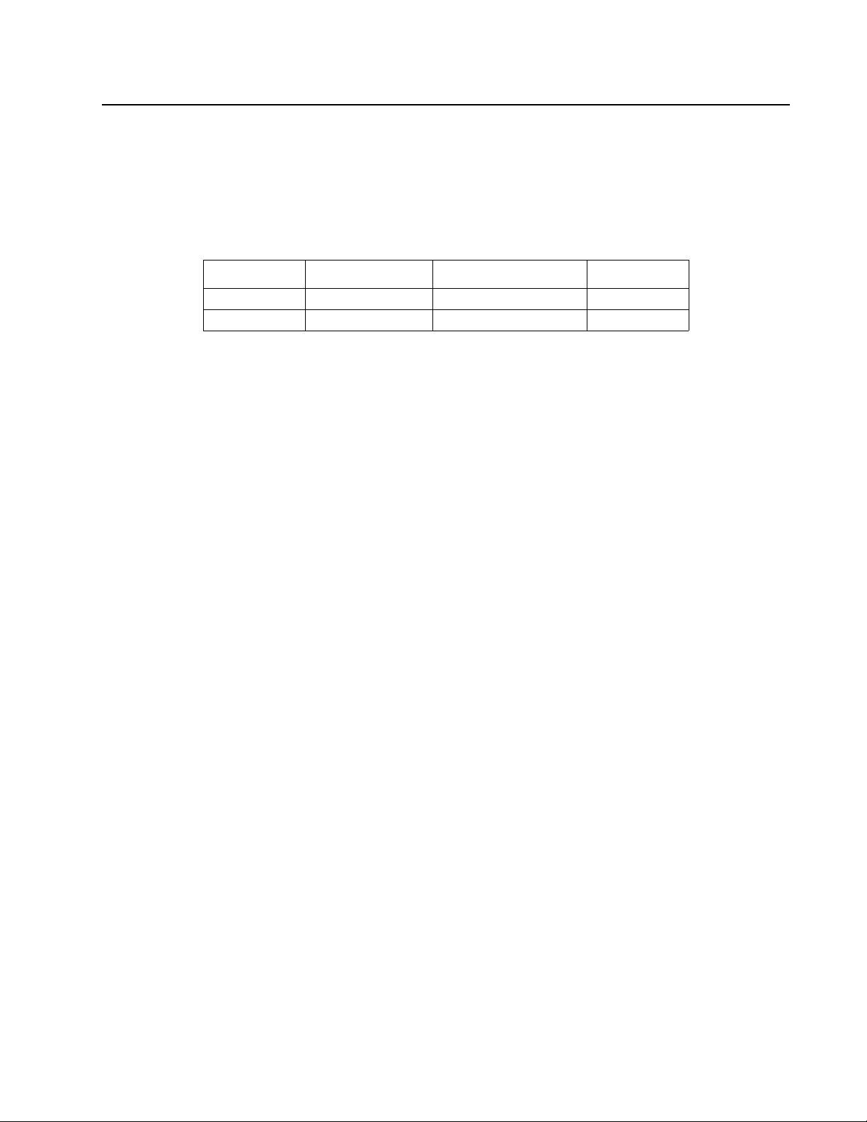
KVM0108A and KVM0116A KVM Switches
The KVM switches allow administrators to access and control multiple servers from a single PS/2 or
USB KMM (keyboard, monitor, and mouse) console. There is no software to configure.
SKU Local Connection Remote Connection KVM Ports
KVM0108A 1 0 8
KVM0116A 1 0 16
• An auto-sensing function recognizes the position of each station on the installation, eliminating
the need to manually set the position, and a front panel LED displays each station's position.
• Updates are available at www.apc.com. The Firmware Upgrade function performs installation.
Features
• Simple installation and operation: Plug-and-play installation. No software required. Station
positions are automatically recognized. Computer selection is done using hotkeys or multilanguage On Screen Display (OSD) menus.
• Single console control: Access and control up to 8 (KVM0108A) or 16 (KVM0116A) servers
from a single PS/2 or USB KVM (keyboard, monitor, and mouse) console.
• Scalability: Connect up to 31 switches. Control up to 512 servers (KVM0116A) from the KVM
console.
• Easy installation: Plug cables into their appropriate ports. No software to configure.
• Hardware independent cross-platform support.
• RJ-45 connectors and cat 5e/6 cabling: The KVM0108A or KVM0116A can be installed in a 1U
system rack. Take advantage of internal network wiring in most modern commercial buildings.
• KVM adapter cables connect to servers. Mix PS/2 and USB interfaces connecting the KVM
switch to the devices.
• Strong password protection prevents unauthorized access.
• Multiple user accounts: Supports up to 10 user and 1 administrator accounts.
• Effortless upgrades: Simultaneously upgrade all in series KVM switches and server modules.
• Auto scanning and broadcast mode: Auto scanning provides hands-free monitoring of selected
devices at variable rates. Broadcast Mode sends commands from the console to all computers.
Performs software installation, upgrades, and shutdowns simultaneously.
• Superior video quality: Supports the video resolutions up to 1600x1200@60hz for up to 40
meters, and 1280x1024@75hz for up to 50 meters with the KVM Cable Adapter.
• Hot pluggable: Add or remove components without powering off the KVM switch.
• Server modules (Adapter cables) with ID: The KVM switch automatically recognizes the new
KVM Cable Adapter. Device ID and attributes are stored in the adapter cables allowing you to
hot-swap port connections without having to reconfigure attributes.
1KVM Switches KVM0108A and KVM0116A User Manual

Safety
Read all of these instructions. Save them for future reference. Follow all warnings and instructions
marked on the device.
DANGER
HAZARD OF ELECTRIC SHOCK
• Do not use the device near water, Never spill liquid of any kind on the device.
• Unplug the device from the wall outlet before cleaning. Do not use liquid or aerosol
cleaners. Use a damp cloth for cleaning.
• The device should be operated from the type of power source indicated on the
marking label. If you are not sure of the type of power available, consult your
dealer or local power company.
• To prevent damage to your installation it is important that all devices are properly
grounded. The device is equipped with a 3-wire grounding type plug. This is a
safety feature. If you are unable to insert the plug into the outlet, contact your
electrician to replace the outlet. Do not attempt to defeat the purpose of the
grounding-type plug. Always follow local/national wiring codes.
• If an extension cord is used with this device make sure that the total of the ampere
ratings of all products used on this cord does not exceed the extension cord
ampere rating. Make sure that the total of all products plugged into the wall outlet
does not exceed 15 amperes.
• To help protect your system from sudden, transient increases and decreases in
electrical power, use a surge suppressor, line conditioner, or uninterruptible power
supply (UPS).
• Position system cables and power cables carefully; Be sure that nothing rests on
any cables.
• Never push objects of any kind into or through cabinet slots. They may touch
dangerous voltage points or short out parts resulting in a risk of fire or electrical
shock.
• Use the power cord(s) supplied with this package. If it becomes necessary to
replace the cords supplied with this package, be sure to use cords of at least the
same standard as the ones provided. Contact your dealer for information about
power cords
• Do not attempt to service the device yourself. Refer all servicing to qualified service
personnel.
Failure to follow these instructions can result in death or serious injury.
KVM Switches KVM0108A and KVM0116A User Manual2

CAUTION
INJURY OR EQUIPMENT DAMAGE
• Do not connect the RJ-11 connector marked “UPGRADE” to a public
telecommunication network.
• Before working on the rack, make sure that the stabilizers are secured to the rack,
extended to the floor, and that the full weight of the rack rests on the floor. Install
front and side stabilizers on a single rack or front stabilizers for joined multiple
racks before working on the rack.
• Always load the rack from the bottom up, and load the heaviest item in the rack
first.
• Make sure that the rack is level and stable before extending a device from the rack.
• Use caution when pressing the device rail release latches and sliding a device into
or out of a rack; the slide rails can pinch your fingers.
• After a device is inserted into the rack, carefully extend the rail into a locking
position, and then slide the device into the rack.
• Do not overload the AC supply branch circuit that provides power to the rack. The
total rack load should not exceed 80 percent of the branch circuit rating.
• Make sure that all equipment used on the rack, including power strips and other
electrical connectors, is properly grounded.
• Ensure that proper airflow is provided to devices in the rack.
• Ensure that the operating ambient temperature of the rack environment does not
exceed the maximum ambient temperature specified for the equipment by the
manufacturer
• Do not step on or stand on any device when servicing other devices in a rack.
• Do not place the device on an unstable surface. If the device falls, serious damage
will result.
• Do not block ventilation openings. Overheating of internal components may occur.
• Route the power cord and cables so that they cannot be stepped on or tripped
over.
Failure to follow these instructions can result in injury or equipment damage.
Taking Delivery
Examine the components at the time of delivery to be sure all parts are present and in good working
order. Anything missing or damaged must be reported immediately to the shipping firm and to APC.
Accessory Inventory
• 1 KVM0108A or KVM0116A KVM switch
• 1 firmware upgrade cable
• 1 NEMA 5-15 power cord
1 C13 - C14 power cord
• 1 rack mount bracket
• Literature Kit: Quick Start Guide, Safety Sheet, and China ROHS.
3KVM Switches KVM0108A and KVM0116A User Manual

Requirements
Console
• VGA, SVGA, or multi-sync monitor capable of the highest resolution that you will be using on
any server in the installation
• PS/2 or USB mouse/keyboard
Computers
The following equipment must be installed on the servers that connect to the KVM switch ports:
• VGA, SVGA, or multi-sync port
• Type A USB port and USB host controller
• or 6-pin Mini-DIN keyboard and mouse ports
KVM Server Modules and cables
• The Cat 5e/6 cable is required to connect the KVM switch to one of the KVM adapter cables.
• The following KVM adapter cables are required for use with the KVM switch:
Module Function
KVM-PS2 Connects to devices with PS/2 ports
KVM-USB Connects to devices with USB ports
AP5262 APC KVM Chain In/Out Cable - 2 ft (0.6 m)
AP5263 APC KVM Chain In/Out Cable - 6 ft (1.8 m)
Supported operating systems
• Microsoft Windows
• Linux
• UNIX
• Mac
• DOS
Maximum server connections
Parent
KVM Model
KVM0108A 8 KVM0108A 8 265 32
KVM0116A 16 KVM0216A 16 512 32
Ports Child
Tiered KVM
Ports Max Connections
(Tiered)
Chained
Connections
KVM Switches KVM0108A and KVM0116A User Manual4

Component Identification
aem0465a
Power
1 2 3 4 5 6 7 8 9 10111213141516
Power
12345678
KVM0108A
KVM0116A
F/W Upgrade
Normal-Recover
F/W Upgrade
Station ID
Reset
F/W Upgrade
Normal-Recover
F/W Upgrade
Station ID
Reset
Front
No. Component Description
Power LED Lights to indicate that the KVM switch is powered and ready to operate.
1
Port LEDs The Port LEDs provide status information about their corresponding KVM Ports
2
• GREEN: The server attached to the port is On Line.
• RED: The server attached to the port is Selected (has KVM focus).
• GREEN + RED (ORANGE): The server attached to the port is On Line and Selected.
The LEDs are continuously ON under normal conditions. An LED will flash at half second
intervals when its corresponding port is accessed under Auto Scan Mode or Skip Mode
Firmware Upgrade
3
Recovery Switch
Reset Switch The switch is recessed and must be pushed with a small object, such as the end of a paper clip
4
Station ID LED The KVM switch's Station ID is displayed here. If this is a single station installation or the
5
Firmware Upgrade
6
Port
Console Port The port is for installation with Rack LCD Console AP5717 or AP5719.
7
During normal operation and while performing a firmware upgrade, this switch should be in
the “normal” position. If a firmware upgrade operation does not complete successfully, this
switch is used to perform a firmware upgrade recovery (see “Firmware Upgrade Utility” on
page 29).
or a ballpoint pen. To perform a system reset, press and release when the unit is running.
Note: This does not clear User Account information.
first station on the installation, the KVM switch ID is “01.”
On a tiered installation, the KVM switch auto-senses its position and displays the station ID
that corresponds to its place in the installation (see “Port ID Numbering” on page 12).
The Firmware Upgrade Cable that transfers the firmware upgrade data from the
administrator's computer to the KVM switch, plugs into this RJ-11 connector.
5KVM Switches KVM0108A and KVM0116A User Manual

Rear
aem0464a
KVM0108A
KVM0116A
Item Component Description
Power Socket The power cord to the AC source plugs in here.
1
Chain In/Out Ports When cascading KVM switches, the cables plug in here (see “Tiering multiple KVM
2
switches” on page 9).
The port on the left is the Chain In port; the port on the right is the Chain Out port.
KVM Port Section The Cat 5e/6 cables that link to the KVM adapter cables (which link to the computers)
3
plug in here.
Console Ports If this is a single station installation, or if this is the first station of a tiered installation,
4
the keyboard, monitor, and mouse that make up the Local Console plug in here.
Any combination of PS/2 and USB keyboards and mice for the console may be used.
KVM Switches KVM0108A and KVM0116A User Manual6
 Loading...