

User’s manual
Retain for future use
Altivar 71
Crane card
VW3A3510


Contents
Important information _________________________________________________________________________________________ 4
Before you begin_____________________________________________________________________________________________ 5
Documentation structure_______________________________________________________________________________________ 6
Description _________________________________________________________________________________________________ 7
Description of the terminals _________________________________________________________________________________ 8
Characteristics ___________________________________________________________________________________________ 9
Data backup battery ______________________________________________________________________________________ 10
Operating principle __________________________________________________________________________________________ 12
General________________________________________________________________________________________________ 12
Anti-sway operator assistance ______________________________________________________________________________ 13
Cable length acquisition ___________________________________________________________________________________ 14
Input/Output functions________________________________________________________________________________________ 17
Assistance activation function_______________________________________________________________________________ 19
End limit switch function___________________________________________________________________________________ 19
Slowing down switch function_______________________________________________________________________________ 20
Menus - Parameter settings ___________________________________________________________________________________ 21
CANopen configuration_________________________________________________________________________________ ___ 21
General configuration_____________________________________________________________________________________ 22
Forced local mode _______________________________________________________________________________________ 24
Fault reset______________________________________________________________________________________________ 24
Fault management _______________________________________________________________________________________ 24
Parameters in the [1.14 Crane] (SPL-) menu___________________________________________________________________ 25
Connection diagram _________________________________________________________________________________________ 30
Commissioning_____________________________________________________________________________________________ 31
1 - Configure the motor parameters via the [1.4 MOTOR CONTROL] (drC-) menu______________________________________ 31
2 - Wiring the crane card and the application part _______________________________________________________________ 31
3 - Establish the CANopen connection________________________________________________________________________ 32
4 - Set the parameters of the "crane application"________________________________________________________________ 35
5 - Start up the system with the crane card and check the movements_______________________________________________ 35
6 - Understanding the most important parameters for activating anti-sway assistance ___________________________________ 36
7 - Slowing down switch and end limit switches_________________________________________________________________ 43
3
Important information
The presence of this symbol on a danger or warning label indicates that there is a risk of electrocution, which can cause
bodily injury if the instructions are not followed.
This is the symbol for a safety warning. It warns you of a potential danger of bodily injury. Follow all the safety instructions
accompanying this symbol to avoid any situation that can result in injury or death.
PLEASE NOTE
Please read these instructions carefully and examine the device in order to familiarize yourself with it before installation, operation or
maintenance. The specific messages which follow can appear in the documentation or on the device. They warn you of potential dangers
or draw your attention to information which can clarify or simplify a procedure.
DANGER
DANGER indicates a dangerous situation resulting in death, se rious injury or equipment damage.
WARNING
WARNING indicates a situation involving risks that can cause death, serious injury or equipment damage.
CAUTION
CAUTION indicates a potentially dangerous situation that can result in bodily injury or equipment damage.
IMPORTANT NOTE
The maintenance of electrical equipme nt must only p erformed by qualif ied personnel. Schneider Electric c an in no way be held responsible
for the consequences of using this documentatio n. Thi s document is n ot intend ed t o be us ed as a gui de b y person s who ha ve recei ved no
training.
© 2008 Schneider Electric. All rights reserved.
4
Before you begin
Important: This option card is fully supported with the version V1.2 and above of the Altivar 71 firmware. This option card is only
supported with the version V1.2 and above of Altivar 31 firmware. Specific versions are not supported.
Read and understand these instructions before performing any procedure on this drive.
DANGER
RISK OF DANGEROUS VOLTAGE
• Read and understand this manual in full before installing or operating the variable speed drive. Installation, adjustment, repair, and
maintenance must be performed by qualified personnel.
• The user is responsible for compliance with all international and na ti onal el ect rical sta ndards in force conc ernin g protect ive grounding
of all equipment.
• Many parts of this variable speed drive, including the printed circuit boards, operate at the line voltage. DO NOT TOUCH.
Use only electrically insulated tools.
• DO NOT touch unshielded components or terminal strip screw connections with voltage present.
• DO NOT short across terminals PA and PC or across the DC bus capacitors.
• Install and close all the covers before applying power or starting and stopping the drive.
• Before servicing the variable speed drive:
- Disconnect all power.
- Place a "DO NOT TURN ON" label on the variable speed drive disconnect.
- Lock the disconnect in the open position.
• Disconnect all power including external control power that may be present before servicing the drive. Wait for the charging LED to go
off. WAIT 15 MINUTES for the DC bus capacitors to discharge. Then follow the procedure for measuring the DC bus voltage given in
the Installation Manual. The drive LEDs are not accurate indicators of the absence of DC bus voltage.
Failure to follow these instructions will result in death, serious injury or equipment damage.
CAUTION
DAMAGED EQUIPMENT
Do not install or operate any drive that appears damaged.
Failure to follow this instruction can result in bodily injury and/or equipment damage.
5

Documentation structure
Installation Manual
This manual describes:
• How to assemble the drive
• How to connect the drive
Programming Manual
This manual describes:
• The functions
• The parameters
• Use of the drive terminal (integrated display terminal and graphic display terminal)
Communication Parameters Manual
This manual describes:
• The drive parameters with specific information (addresses, formats, etc.) for use via a bus or communication network
• The operating modes specific to communication (state chart)
• The interaction between communication and local control
Communication bus and network manuals (Modbus, CANopen, Ethernet, Profibus, INTERBUS,
DeviceNet, etc.)
These manuals describe:
• Connection to the bus or network
• Configuration of the parameters specific to communication via the integrated display terminal or the graphic display terminal
• Diagnostics
• Software setup
• The protocol communication services
6
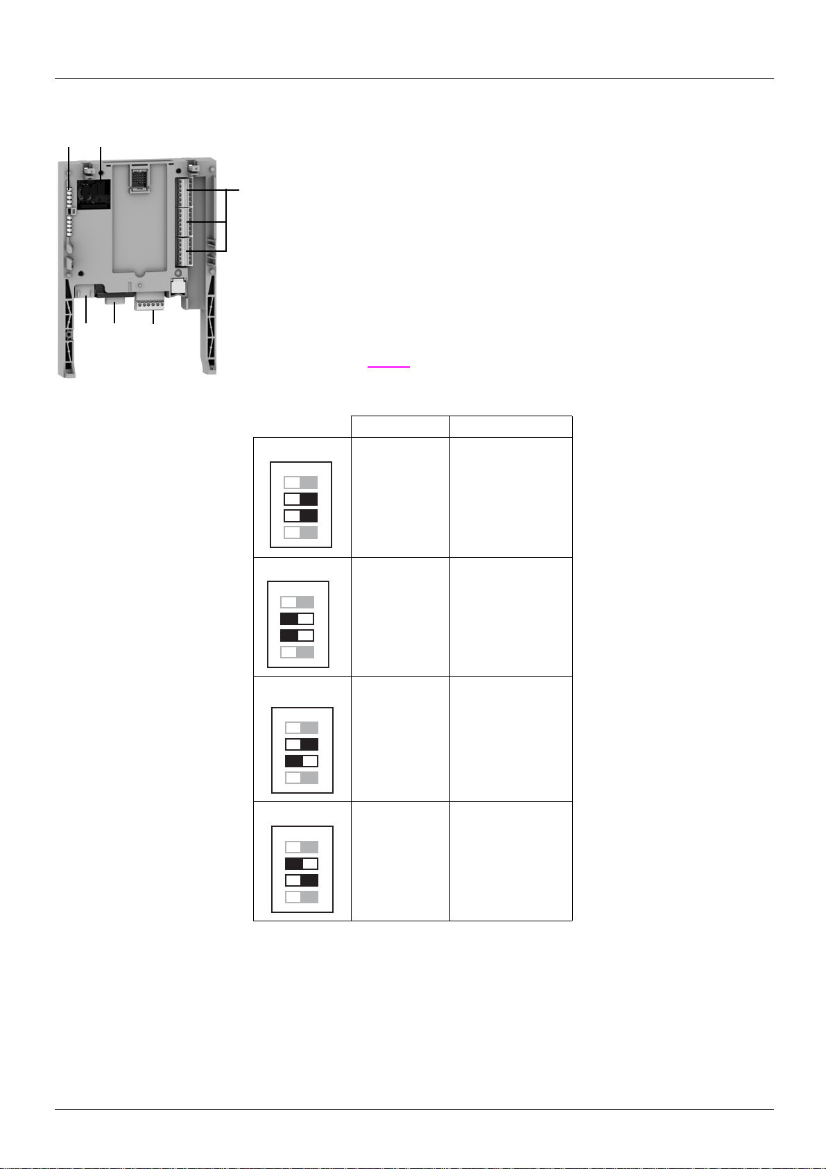
Description
1 23
4
5
6
ON
1
2
3
4
ON
1
2
3
4
ON
1
2
3
4
ON
1
2
3
4
1 RJ45 connector
2 9-way male SUB-D connector for connection to the CANopen bus
3 Connector with removable screw terminals, 6 contacts at intervals of 3.81 for the
24 V c power supply and 4 logic inputs
4 3 connectors with removable screw terminals, 6 contacts at intervals of 3.81 for 6 logi c inpu ts,
6 logic outputs, 2 analog inputs, 2 analog outputs and 2
commons
5 5 LEDs, comprising:
• 1 to indicate the presence of the 24 V c power supply
• 1 to indicate a program execution fault
• 2 to indicate the CANopen bus communication status
• 1 controlled by the application program
6 Block of 4 configuration switches. Switches 2 and 3 are used to configure the topology of the
installation (see
page 21). Four cases are possible. Select the co rrect co nfigurati on accordi ng
to the following table:
Crane Trolley
(1)
ATV31
(2 = ON)
ATV71
(2 = OFF)
ATV31
(3 = ON)
ATV71
(3 = OFF)
The switches represented in grey are not used to choose the configuration.
(1) The card is delivered in this configuration.
ATV31
(2 = ON)
ATV71
(2 = OFF)
ATV71
(3 = OFF)
ATV31
(3 = ON)
7
Hardware setup
LI55
LI60
LI59
LI58
LI57
LI56
LO51
LO56
LO55
LO54
LO53
LO52
AI51
AO52
COM
AO51
AI52
COM
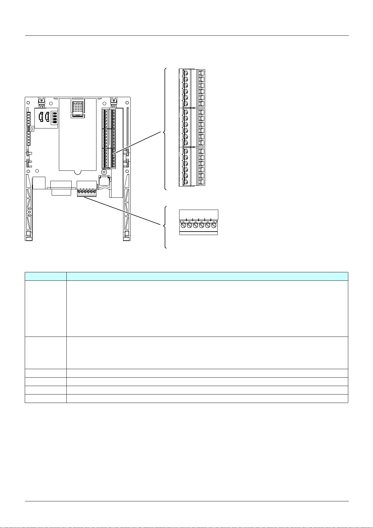
Description of the terminals
Figure 1
Terminals Function
24V Power supply for the crane card, logic outputs and analog outputs.
If allowed by the power consumption table (for example if outputs are not being used), the crane card can be powered
by the 24 V
If you are using an external power supply:
• The crane card must be turned on before the drive is turned on, or at the same time as the drive is turned on.
If this order is not followed, the drive will lock in a card fault (ILF). This fault cannot be reset, and the only way to
acknowledge it is to turn off the drive.
• Catalog number for a Telemecanique power supply (24 V
COM
(3 terminals)
LI51 to LI60 24 V
LO51 to LO56 24 V
AI51 and AI52 0...20mA analog inputs
AO51 and AO52 0...20mA analog outputs
Common ground and electrical 0V of the crane card power supply, logic inputs, (LI
pp) and analog outputs (AOpp).
(AI
This ground and electrical 0V are common with the drive ground and electrical 0V. There is therefore no point in
connecting this terminal to the 0V terminal on the drive control terminals.
c power supply in the drive.
c logic inputs
c logic outputs
c, 2A): ABL7 RE 24 02.
pp), outputs (LOpp), analog inputs
8

Hardware setup
Characteristics
Electrical characteristics
Power supply Voltage V 24 c (min. 19, max. 30)
Current
consumption
Logic inputs LI51…LI60 Impedance 4.4 kΩ
Logic outputs LO51…LO56 Six 24 V c logic outputs, positive logic open collector type (source),
I/O connection Type of contact Screw, at intervals of 3.81 mm
Lithium battery Life 8 years
Maximum A 2
No-load mA 80
Using logic output mA 200 maximum (1)
Maximum voltage: 30 V c
Switching thresholds:
State 0 if y 5 V or logic input not wired
State 1 if u 11 V
Common point for all the card I/O (2)
compatible with level 1 PLC, standard IEC 65A-68
Maximum switching voltage: 30 V
Maximum current: 200 mA
Common point for all the card I/O (2)
Maximum capacity mm21.5 (AWG 16)
Tightening torque
Nm
0.25
2
(1)If the power consumption table does not exceed 200 mA, this card can be powered by the drive. Otherwise, an external 24 V c power supply must be used.
(2)This common point is also the drive 0 V (COM).
9
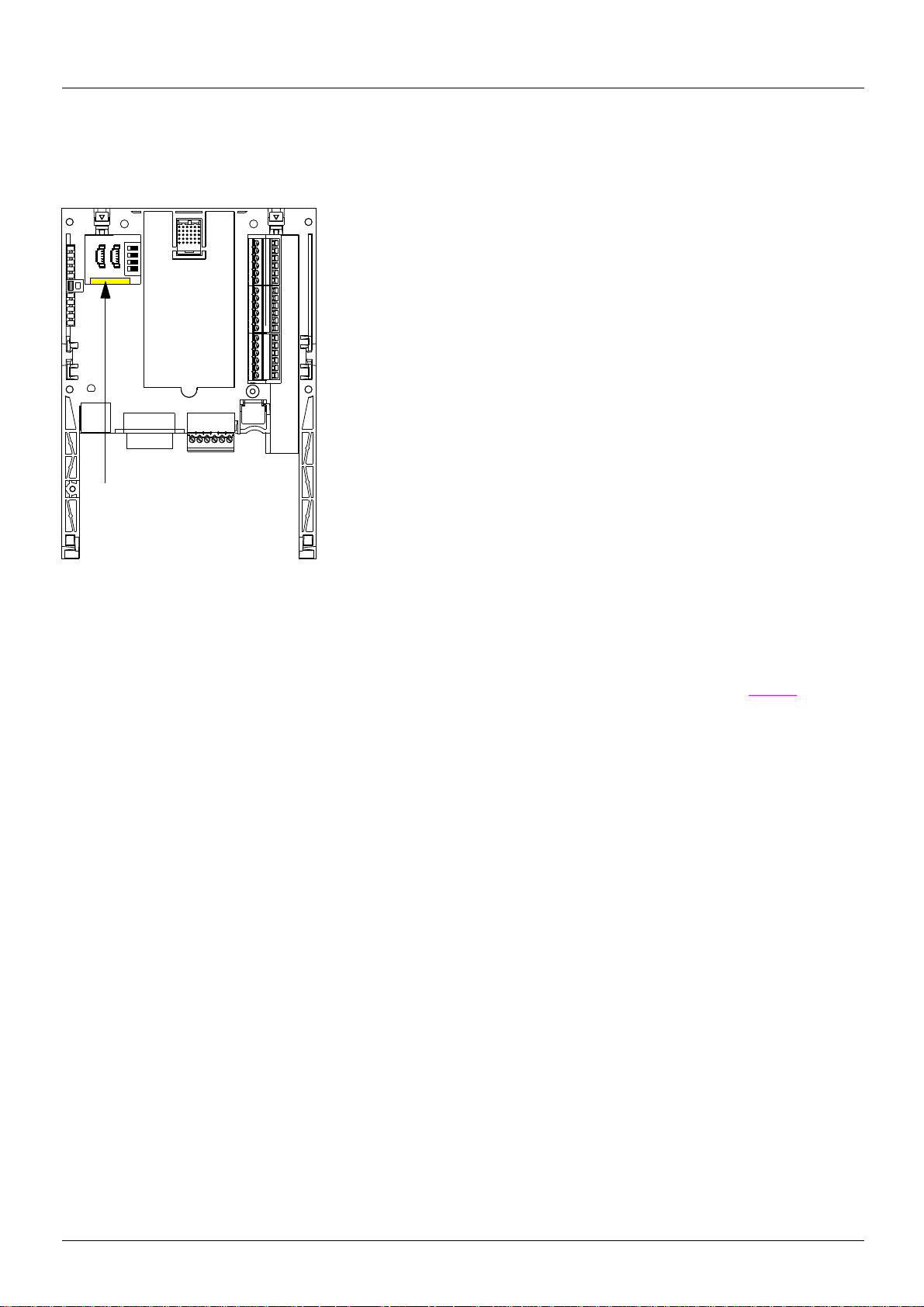
Hardware setup
When installing the crane card in the drive, make sure t hat this batte ry is present. I t takes
the form of a rectangular block clipped onto the non-volatile RAM (see schematic
opposite).
The battery life is 8 years.
The battery has a realtime clock for timestamping faults.
The date and time on this clock are checked and set from a special sub-menu in the
[1.14 - Crane] (SLE-) customizable menu in the graphic display terminal.
The date and time need to be set on receipt of the crane card, or after replacing its lithium
battery.
The lithium battery must only be replaced when the drive and the crane card are turned
off.
During this operation, the data saved in the NVRAM (4 Kwords) is lost.
Lithium
battery
Data backup battery
The crane card has a non-volatile RAM (NVRAM) which is needed to store v ariables. A lit hium battery is mount ed on this non -volatile RAM
to avoid this data being lost when the card is turned off.
Figure 2
Important 1:
There is no spare part catalog number for the battery because of the issue of storage life. Users are responsible for ordering their own
replacement battery. The battery product reference is TIMEKEEP ER SNAPHAT M4T28-BR12SH1 (48mAh).
Important 2:
If the battery is changed, the crane card return automatically in factory setting (see parameter O32 [FACTORY_SET] page 28). The logic
output LO52 stays to 0 V to the next starting of the crane card without problem.
10
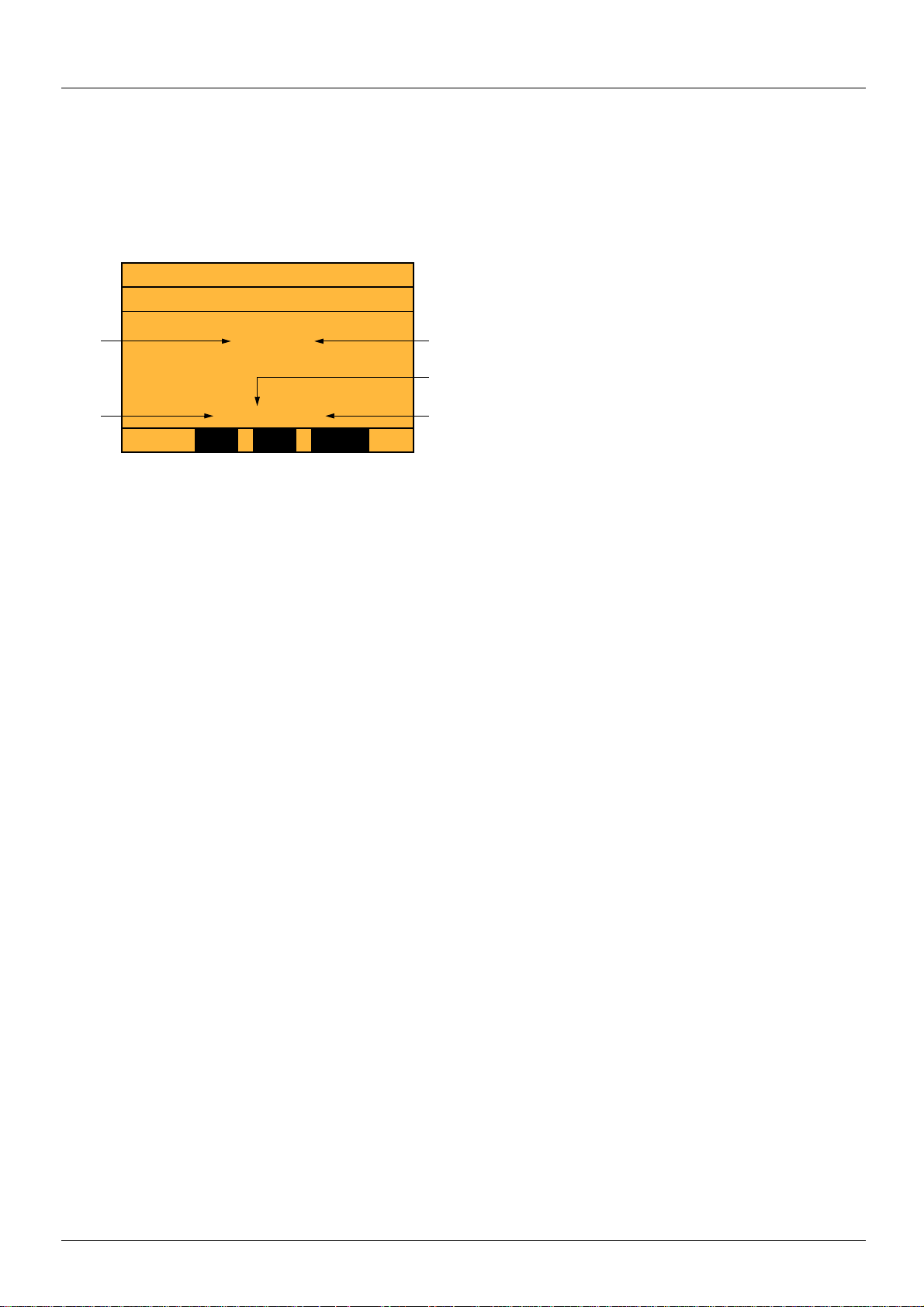
Operation using the graphic display terminal
NST Term 0.00Hz 0.0A
DATE/TIME SETTINGS
22 : 42
11 / 03 / 2005
<< >> Quick
Hour
YearDay
Minutes
Month
Setting the date and time
The following information can be set in the [1.14 Crane] (SPL-) menu, [DATE/TIME SETTINGS] submenu:
- Year
- Month
- Day
- Hours
- Minutes
Note: The date and time are not refreshed on this settings screen. The current date and time [Date/Time] (CLO) can be displayed in the
[1.2 MONITORING] (SUP-) menu.
Note: It is not possible to change either the date or time format:
• The date cannot be displayed in the "year/month/day" format.
• The time cannot be displayed in the "10:42 pm" format, only in the "2 2:42" format.
Note: It is not possible to configure changes between winter and summer time.
11
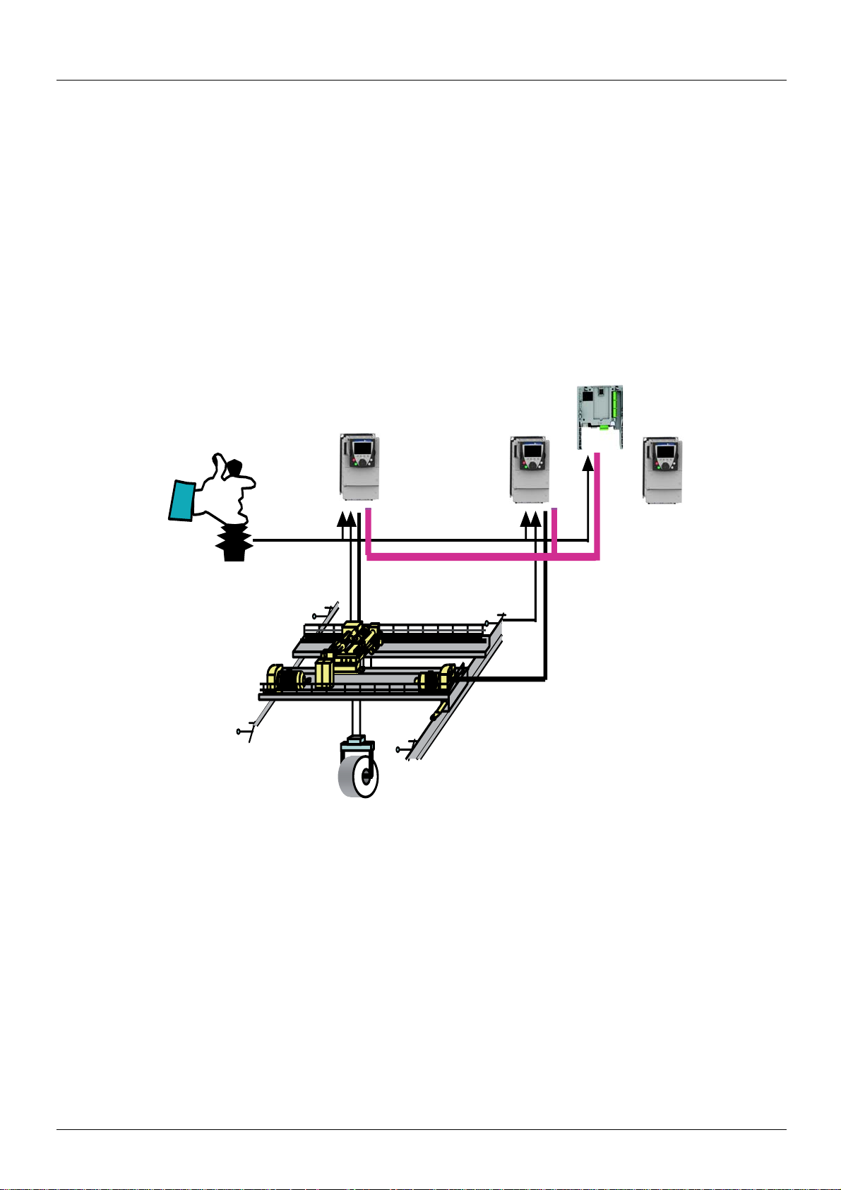
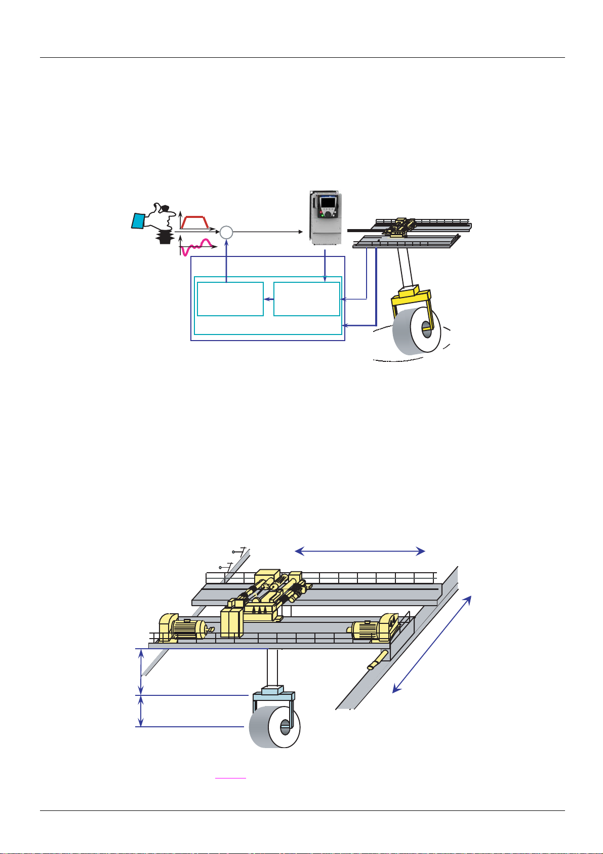
Operating principle
Trolley
Crane card
Hoist
Crane
General
The main objective is to control load sway without using additional sensors.
The crane card can be integrated easily in a standard drive. The same electrical operator interface is used without the need for any wiring
modification.
The card is integrated by automatic drive recognition and takes control in order to manage the entire system via CANopen fieldbus.
Safety zones are managed through limit switches (slowing down switch and end limit switch). The anti-sway operator assistance works
simultaneously on 2 axes (including trolley, crane and hoist for position feedback).
Application example with 3 drives (trolley, hoist and crane):
CAN
Figure 3
12
Operating principle
Controller
Estimator
Safety control
SWAY
Trolley
Right
Left
Crane
Forward
Reverse
End limit switch
Slowing down switch
L_Cable
[LOAD_LENGTH]
(O29)
Anti-sway operator assistance
Suspended loads are subject to sway during trolley (or crane) movement. Only experienced operators can efficiently bring a load to a
sway-free stop without the crane card. Use of t he c rane card offers sig nif icant t ime sa vin gs, since it means th at no time is l os t waiti ng for a
load to stop swaying or during difficult fine positioning operations.
SWAY assists the crane operator by modifying the speed command signal to the movement driv e so that sway is continuously limited. When
the load is brought to the desired speed or to a halt, there is a little or no sway.
+
L
Figure 4
Estimator
An adaptive model is used to estimate load sway based on:
- the drive’s internal signals
- the cable length
Controller
This is an adaptive continuous controller providing anti-sway correction to the operator command.
Safety control
- Safety zones for slowing down and stopping
- Activation and deactivation of the anti-sway assistance
Figure 5
The parameter [LOAD_LENGTH] (O29) (see page 27) must be used if the load is repetitive and if this information is available.
13
Operating principle
LI58 =
up limit switch
LI58 =
up limit switch
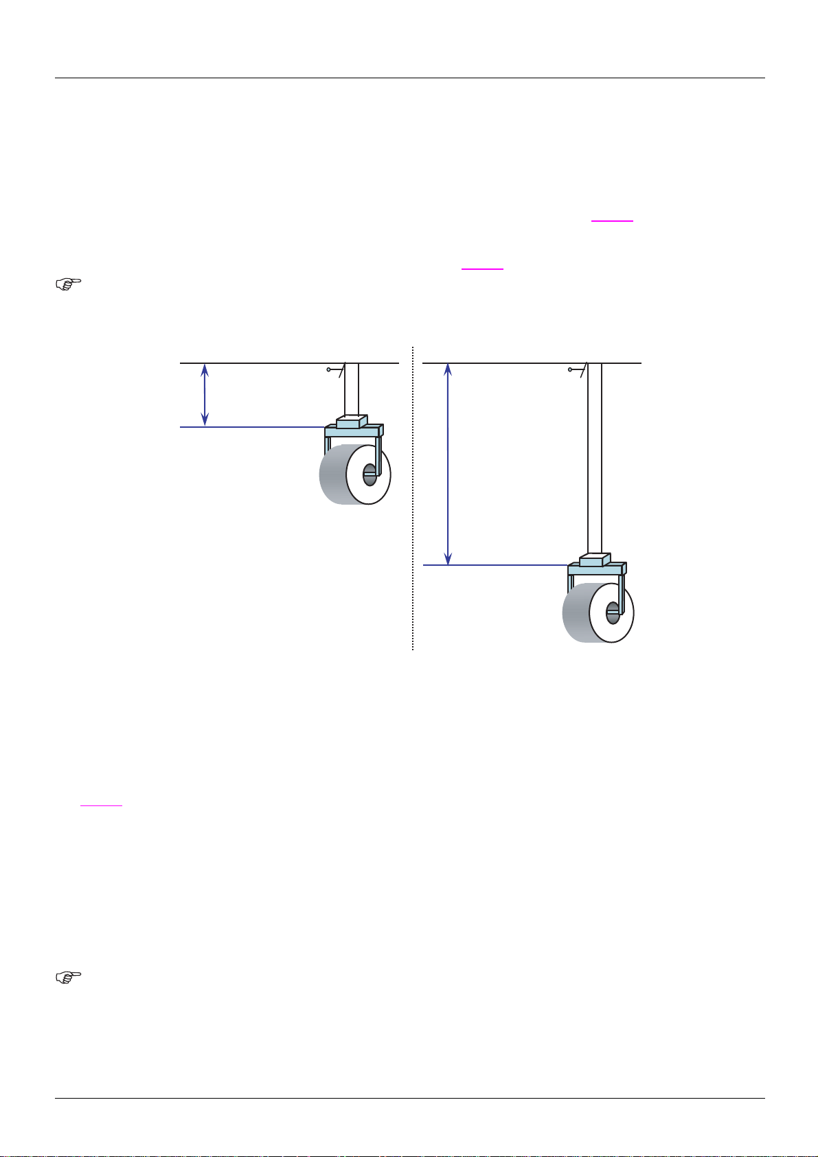
Cable length acquisition
There are three methods for measuring the load cable length:
• Via encoder
• Via input from 2 limit switches on the hoist
• Via input from a 3-position selector
The method is selected via parameter [ACQ_CBL_CONF] (O25) in the [1.14 Crane] (SPL-) menu (see page 27).
Method 1: Via encoder
This method is selected when [ACQ_CBL_CONF] (O25) = [encoder] (1) (see page 27).
Important : The choose of this method i mplies 2 points for the hoisting drive:
• It must be connected to CANopen in order to be able to read encoder value through the fieldbus
• It must be configured in closed loop current flux vertor control [FVC] (FUC) and the encoder test must have been done (see ATV71
programming manual).
Logic input LI58 is used for the up limit switch.
Figure 6
Step 1:
Logic output LO51 flashes until the up limit switch is reached.
Move the load to the up limit switch position (LI58 = 1). The value of the encod er position is set t o 0 each time the u p limit switch is activated.
Step 2:
Lower the load and enter the corresponding cable length in parameter [RES_ENC] (O38) in the [1.14 Crane] (SPL-) menu on the keypad
page 28).
(see
Important: In order to ensure optimum accuracy, it is necessary to use the maximum possib le cable length.
The encoder resolution is calculated by the card using the formula:
resolution = ([RES_ENC] (O38) * 10000 pulses) / number of pulses
Example:
[RES_ENC] (O38) = 20 meters
The read value for the encoder position is: number of pulses = 3087210
Encoder resolution = (20 * 10000) / 3087210 = 0.06478 m
This value is used by the software to determine the cable lengt h during nominal operation.
Note: It is possible to recalibrate the cable le ngth (for exampl e, after changi ng the enco der or in the eve nt of a wron g adjustment of
[RES_ENC] (O38)). In this case, it is necessary to switch the value of [ACQ_CBL_CONF] (O25) from [encoder] (1) to
switches] (2), and then return to [encoder] (1). Then restart the procedure from Step 1.
[3
14
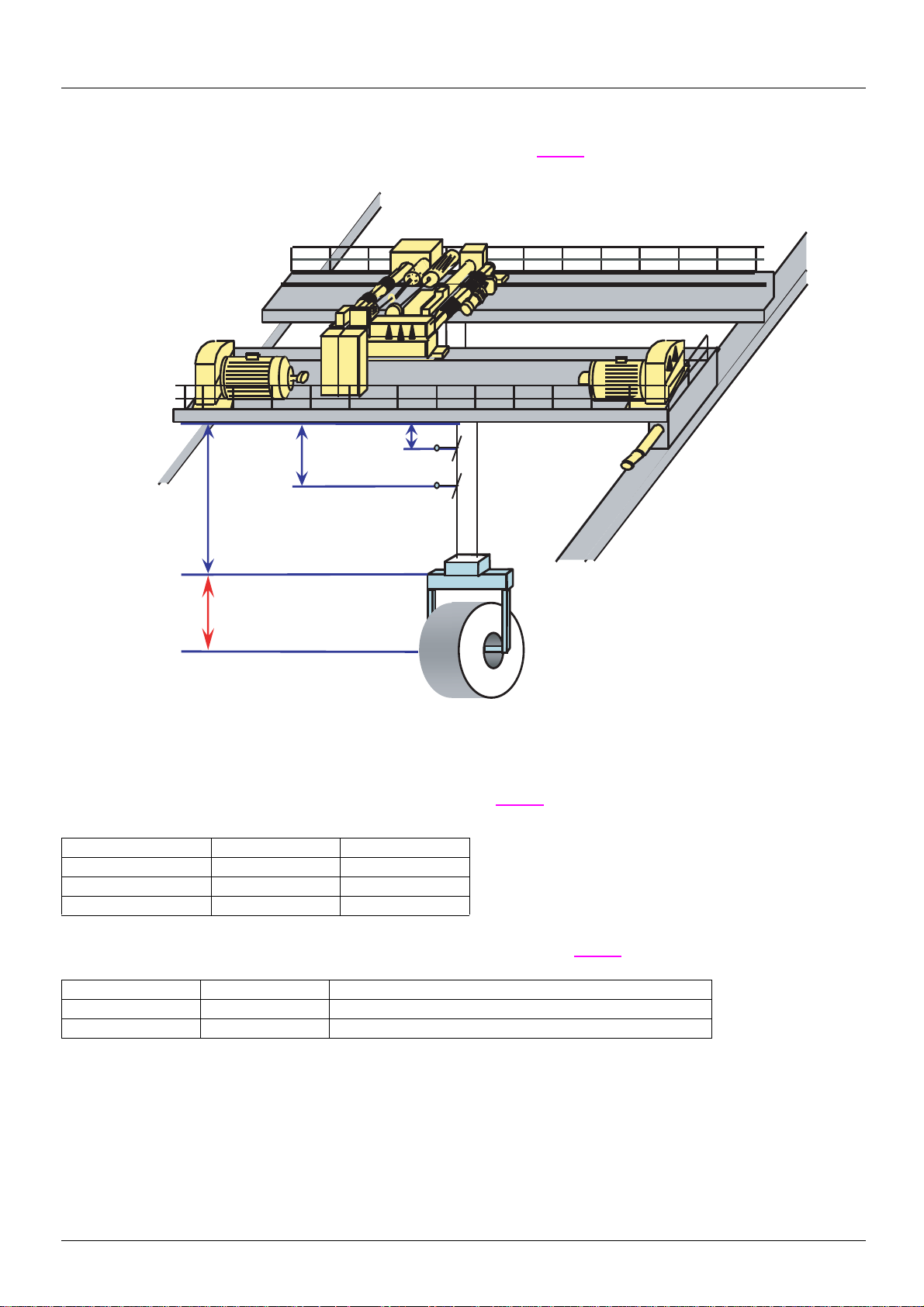
Operating principle
[LOAD_LENGTH]
(O29)
[HIGH_POS]
(O26)
[MIDD_POS]
(O27)
[LOW_POS]
(O28)
LI59
LI58
Method 2: Via input from 2 limit switches on the hoist
This method is selected when [ACQ_CBL_CONF] (O25) = [2 switches] (0) (see page 27).
LI58 and LI59 are symbolic in this figure. The usual way is to use a screw selector to activate LI58 and LI59.
The three parameters [HIGH_POS] (O26), [MIDD_POS] (O27) and [LOW_POS] (O28) correspond to the three working areas of the
installation. They can be configured in the [1.14 Crane] (SPL-) menu (see
During operation, the working area is selected automatically by switches LI58 and LI59 according to the following table:
The load height can imply a shifting of the gravity cente r. To maintai n the accuracy of t he anti-sway fun ction, the prese nce of t he load must
be validated using LI60, in order to automatically add the [LOAD_LENGTH] (O29) (see
Figure 7
page 27).
Working area LI58 LI59
[HIGH_POS] (O26) 0 0
[MIDD_POS] (O27) 1 0
[LOW_POS] (O28) 1 1
page 27):
Description LI60 Total cable length
Load present 1 Result of cable length acquisition + [LOAD_LENGTH] (O29)
Load not present 0 Result of cable length acquisition
15
 Loading...