


User’s Guide
UPS Network
Management Card 2
AP9630, AP9631

本マニュアル<各国の言語に対応する>はウェブサイト (www.apc.com) からダウン
ロードできます
This manual is available in English on the Web site (www.apc.com).
Dieses Handbuch ist in Deutsch auf der Webseite (www.apc.com) verfügbar.
Este manual está disponi ble en español en la página web (www.apc.com).
Ce manuel est disponible en français sur le site internet (www.apc.com).
Questo manuale è disponibile in italiano sul sito web (www.apc.com).
Este manual está disponí vel em português no site (www.apc.com).
Данное руководство на русском языке доступно на сайте (www.apc.com )
在公司的网站上 (www.apc.com) 有本手册的中文版。
웹싸이트 (www.apc.com) 에 한국어 매뉴얼 있습니다 .
This manual is available in English on the enclosed CD.
Dieses Handbuch ist in Deutsch auf der beiliegenden CD-ROM verfügbar.
Este manual está disponible en español en el CD-ROM adjunto.
Ce manuel est disponible en français sur le CD-ROM ci-incl us.
Questo manuale è disponibile in italiano nel CD-ROM allegato.
。
Este manual está disponível em português no CD fornecido.
Данное руководство на русском языке имеется на прилагаемом компакт-диске.
本マニュアルの日本語版は同梱の CD-ROM からご覧になれます。
동봉된 CD 안에 한국어 매뉴얼이 있습니다 .
您可以从包含的 CD 上获得本手册的中文版本。

Introduction
Product Description
Features
The tw
be
open stand ards such as:
- Hypertext Transfer Protocol (HTTP) - Secure SHell (SSH)
- Simple Network Management Protocol
- File Transfer Protocol (FTP) - Secure Copy (SCP)
- Telnet
o Schneider Electric UPS Network Management Card s (NMC) menti oned
low are Web-based, IPv6 Ready products that manage supported devices using multiple
- Hypertext Transfer Protocol over Secure
versions 1 and 3 (SNMPv1, SNMPv3)
The AP9630 Network Management Card 2:
• Provides UPS control and self-test scheduling features
• Provides data and event logs
• Provides support for the PowerChute
• Supports using a Dynamic Host Configuration Protocol (DHCP) or BOOTstrap Protocol (BOOTP)
server to provide the network (TCP/IP) values of the NMC
• Supports using the Remote Monitoring Service (RMS)
• Enables you to configure notification through event logging (by the NMC and Syslog), e-mail, and
SNMP traps. You can configure not ifi catio n for s ingle events or groups o f event s, base d on the sever ity
level or category of events
Sockets Layer (HTTPS)
®
Network Shutdown utility
• Provides the ability to export a user configuration (.ini) file from a configured card to one or more
unconfigured cards without converting the file to a binary file
• Provides a selection of security protocols for authentication and encryption
• Communicates with InfraStruxure
The AP9631 Network Management Card includes all AP9630 Network Management Card features and the
following:
• Provides two USB ports
• Supports two universal input/ output ports, to which you can connect:
– Temperature (AP9335T) or temperature/humidity sensors (AP9335TH)
– Relay input/output connectors that support two input contacts and one output relay (using
AP9810 Dry Contact I/O Accessory)
®
Central or InfraStruxure Manager
1UPS Network Management Card 2 User’s Guide

Devices in which you can install the Network Management Card 2. The NMC can be installe d in:
®
• Any Smart-UPS
model that has an internal expansion slot, or any Symmetra® UPS except the
Symmetra PX 250 or Symmetra PX 500 UPS
®
• MGE
Galaxy® 300, 3500, or 7000
• Expansion Chassis (AP9600)
• Triple Expansion Chassis (AP9604)
IPv4 initial setup
You must define two TCP/IP settings for the NMC before it can operate on the network:
• IP address of the NMC
• IP address of the default gateway (only needed if you are going off segment)
Caution: Do not use the loopback address (127.0.0.1) as the default gateway. Doing so disables the
card. You must then log on using a serial connection and reset the TCP/IP settings to their defaults.
To configure the TCP/IP settings, see the Network Management Card Installation Manual,
available on the Network Management Card Utility CD and in printed form.
For detailed information on how to us e a DHCP server to confi gure the TCP/I P settings at an NMC,
see “TCP/IP and Communication Settings” on page 54.
IPv6 initial setup
IPv6 network configuration provides flexibility to accommodate the user's requirements. To configure the
TCP/IP settings for IPv6, see the user interface online help for details on the options: Manual, Auto
Configuration, DHCPv6 Mode under this menu: Administration > Network > TCP/IP > IPv6 settings.
Network management features
These applications and utilities work with a UPS that connects to the network through an NMC.
• PowerChute Network Shutdown — Provide unattended remote graceful shutdown of computers that
are connected to UPS devices
®
• PowerNet
SETs and GETs and use SNMP traps
• InfraStruxure Centr al — Pr ovi de e nte rpr is e- le vel power management and management of agents, UPS
devices, and environmental monitors.
• Device IP Configuration Wizard — Configure the basic settings of one or more NMCs over the
network
• Security Wizard — Create components needed for high security for the NMC when you are using
Secure Sockets Layer (SSL) and related protocols and encryption routines
Management Information Base (MIB) with a standard MIB browser — Perform SNMP
UPS Network Management Card 2 User’s Guide2

Internal Management Features
Overview
Use the user inte rfac e o r the command line inte rface to vie w the stat us of the UPS and mana ge the UPS an d the
NMC. You can also use SNMP to monitor the status of the UPS.
For more information about the internal user interfaces, see “Web User Interface” on page 28 and
“Command Line Interface (CLI)” on page 8. See “SNMP” on page 58 for information about how
SNMP access to the NMC is controlled.
Access priority for logging on
Only one user at a time can log on to the Network Management Card. The priority for access, beginning with
the highest priority, is as follows:
1. Local access to the command line interface from a computer with a direct serial connection to the
Management Card
2. Telnet or SSH access to the command line interface from a remote computer
3. Web access, either directly or through InfraStruXure Central
Note: SNMP h as Write + and Write access. Write + has top access and enables logging on when
another user is already logged on. Write access is equivalent to Web access.
Types of user accounts
The NMC has three levels of access — Administrator, Device User, and Read-Only User — and these are
protected by user name and password requirements.
• An Administrator can use all of the menus in the user interface and all of the commands in the
command line interface. The default user name and password are both apc.
• A Device User can access only the following:
– In the user interface, rec ent e vent s on the Home tab; the menus on the UPS tab; and the menus of
the Logs tab including the event and data logs, accessible under the Events and Data headings.
(The event and data logs display no button for this user to clear the log).
– In the command line interface, the equivalent features and options.
The default user name is device, and the default password is apc.
• A Read-Only User has the follow ing restricted acces s:
– Access through the user interface only.
– Access to the same tabs and menus as a Device User above, but without the capability to change
configurations, control devices, delete data, or use file transfer options. Links to configuration
options are visible but disabled. (The event and data logs display no button for this user to clear
the log).
The default user name is readonly, and the default password is apc.
To set User Name and Password values for the three account types, see “Setting user access” on
page 51.
3UPS Network Management Card 2 User’s Guide

How to Recover from a Lost Password
You can use a local computer that connects to the Management Card through the serial port to access the
command line interface.
1. Select a serial port at the local computer, and disable any service that uses that port.
2. Connect the provided serial cable (part number 940-0299) to the selected port at the computer and to
the configuration port at the Management Card.
®
3. Run a terminal program ( suc h as HyperTerminal
bits, no parity, 1 stop bit, and no flow control.
) and configure the selected port for 9600 bps, 8 data
4. Press
ENTER, repeatedly if necessary, to display the User Name prompt . If you are un able t o disp lay the
User Name prompt, verify the following:
– The serial port is not in use by another application.
– The terminal settings are correct as specified in step 3.
– The correct cable is being used as specified in step 2.
5. Press the Reset button. The Status LED will flash alternately orange and green. Press the Reset button
a second time immediately while the LED is flashing to reset the user name and password to their
defaults temporarily.
6. Press
ENTER, repeate dly if necess ary, to display t he User Name promp t again, then use the default, apc,
for the user name and password. (If you take longer than 30 seconds to log on after the User Name
prompt is redisplayed, you must repeat step 5 and log on again.)
7. At the command line interface, use the following commands to change the User Name and Password
settings, both of which are now apc:
user -an yourAdministratorName
user -ap yourAdministratorPassword
For example, to change the Administrator user name to Admin, type:
user -an Admin
8. Type quit or exit to log off, reconnect any serial cable you disconnected, and restart any service you
disabled.
UPS Network Management Card 2 User’s Guide4
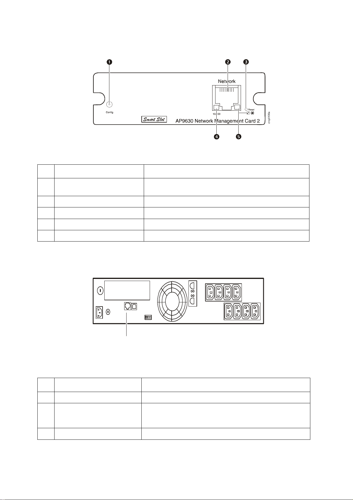
Front Panel (AP9630)
dmp0099a
Features
Item Description
1
Serial configuration port
10/100 Base-T connector Connects the NMC to the Ethernet network.
2
Reset button Resets the NMC while power remains on.
3
Link-RX/TX (10/100) LED See “Link-RX/TX (10/100) LED” on page 6.
4
Status LED See “Status LED” on page 6.
5
Connects the NMC to a local computer to configure initial network
settings or access the command line interface.
Front Panel (AP9631)
Features
Item Description
USB ports Reserved for future use.
1
2
Sensor ports
3
10/100 Base-T connector Connects the NMC to the Ethernet network.
4
Connect temperature sensors, temperature/humidity sensors, or
relay input/output connectors that support two input contacts and
one output relay.
5UPS Network Management Card 2 User’s Guide

Item Description
Reset button Resets the NMC while power remains on.
5
6
Serial configuration port
Link-RX/TX (10/100) LED See “Link-RX/TX (10/100) LED” on page 6.
7
Status LED See “Status LED” on page 6.
8
LED Descriptions
Status LED
This LED indicates the status of the NMC.
Condition Description
One of the following situations exists:
Off
• The NMC is not receiving input power.
• The NMC is not operating properly. It may need to be repaired or replaced. Contact
Customer Support. See “APC Worldwide Customer Support” on page 89.
Connects the NMC to a local computer to configure initial network
settings or access the command line interface.
Solid green The NMC has valid TCP/IP settings.
Solid orange
Flashing green The NMC does not have valid TCP/IP settings.
Flashing orange The NMC is making BOOTP requests.
Alternately flashing
green and orange
1. If you do not us e a BOO TP or DHC P ser ver, see the Netw ork M ana gem ent Ca rd Insta llatio n Manual prov ided in
printed forma t and on the Network Ma nagem ent Car d Utility CD in PDF to configure the TCP/IP settings of the
NMC.
2. To use a DHCP server, see “TCP /IP and Communication Settings” on page 5 4.
A hardware failure has been detected in the NMC. Contact Customer Support. See
“APC Worldwide Customer Support” on page 89.
1
1
If the LED is flashing slowly, the NMC is making DHCP2 requests.
If the LED is flashing rapidly, the NMC is starting up.
1
Link-RX/TX (10/100) LED
This LED indicates the network status of the NMC.
Condition Description
One or more of the following situations exist:
• The NMC is not receiving input power.
Off
• The cable that connects the NMC to the network is disconnected or defective.
• The device that connects the NMC to the network is turned off or not operating
correctly.
Off (continued)
Solid green The NMC is connected to a network operating at 10 Megabits per second (Mbps).
Solid orange The NMC is connected to a network operating at 100 Mbps.
• The NMC itself is not operating properly. It may need to be repaired or replaced.
Contact Customer Support. See “APC Worldwide Customer Support” on page 89.
UPS Network Management Card 2 User’s Guide6

Condition Description
Flashing green The NMC is receiving or transmitting data packets at 10 Mbps.
Flashing orange The NMC is receiving or transmitting data packets at 100 Mbps.
Watchdog Features
Overview
To detect internal problems and recover from unanticipated inputs, the Management Card uses internal,
system-wide watchdog mechani sms. When it rest arts to re cover from an i nter nal pr oblem, a System: Networ k
Interface restarted event is recorded in the event log.
Network interface watchdog mechanism
The Management Card implements internal watchdog mechanisms to protect itself from becoming
inaccessible over the network. For example, if the Management Card does not receive any network traffic for
9.5 minutes (either direct traffic, such as SNMP, or broadcast traffic, such as an Address Resolution Protocol
[ARP] request), it assumes that there is a problem with its network interface and restarts.
Resetting the network timer
To ensure that the Management Card does not restart if the network is quiet for 9.5 minutes, the Management
Card attempts to contact the default gateway every 4.5 minutes. If the gateway is present, it responds to the
Management Card, and that response re st arts th e 9.5-minut e timer. If your application does not requi re or have
a gateway, specify the IP address of a computer that is running on the network and is on the same subnet. The
network traffic of that computer will res tart the 9.5-minu te timer frequentl y enough to prevent th e Management
Card from restarting.
7UPS Network Management Card 2 User’s Guide

Command Line Interface (CLI)
How To Log On
Overview
To access the command line interface, you can use either a local, serial connection, or a remote connection
(Telnet or SSH) with a computer on the same network as the Network Management Card (NMC).
Use case-sensitive user name and password entries to log on (by default, apc and apc for an Administrator, or
device and apc for a Device User). A Read-Only User cannot access the command line interface.
If you cannot remember your user name or pas swor d, se e “How to Recove r f rom a Los t Pas swor d”
on page 4.
Remote access to the command line interface
You can access the comma nd l i ne i nt er fac e t hr ough Telnet or SSH. Telnet is enab led by default. Enabling SSH
disables Telnet.
To enable or disable these access methods , use the Web int er fac e. On t he Administration tab, select Network
on the top menu bar, and then the access option under Console on the left navigation menu.
Telnet for basic access. Telnet provides th e basic s ecurity of authen ticatio n by user n ame and pass word, but
not the high-security benefits of encryption.
To use Telnet to access the command line interface:
1. From a computer that has acc ess to networ k on which the NMC is insta lled, at a command prompt, ty pe
telnet and the IP address for the NMC (for example, telnet 139.225.6.133, when the NMC
uses the default Telnet port of 23), and press
If the NMC uses a non-default por t number ( from 5000 to 32 768), you must include a colon or a spa ce,
depending on your Telnet client, between the IP address (or DNS name) and the port number. (These
are commands for general usage: some clients don’t allow you to specify the port as an argument and
some types of Linux might want extra commands).
2. Enter the user name and password (b y defaul t, apc and apc for an Administrator, or device and apc for
a Device User).
SSH for high-security access. If you use the high sec urity of SSL fo r the Web interf ace, use S SH for access
to the command line interface. SSH encrypts user names, passwords, and transmitted data. The interface, user
accounts, and user access rights are the same whether you access the command line interface through SSH or
Telnet, but to use SSH, you must first configure SSH and have an SSH client program installed on your
computer.
ENTER.
UPS Network Management Card 2 User’s Guide8

Local access to the command line interface
American Power Conversion Network Management Card AOS vx.x.x
(c)Copyright 2010 All Rights Reserved Symmetra APP vx.x.x
------------------------------------------------------------------------- Name : Test Lab Date : 10/30/2010
Contact : Don Adams Time : 5:58:30
Location : Building 3 User : Administrator
Up Time : 0 Days, 21 Hours, 21 Minutes Stat : P+ N+ A+
APC>
For local access, use a computer that connects to the Network Management Card through the serial port to
access the command line interface:
1. Select a serial port at the computer and disable any service that uses the port.
2. Connect the provided serial cable (part numbe r 940-0299) from the select ed port on the computer t o the
configuration port at the NMC.
3. Run a terminal program ( e.g., HyperTerminal), and configu re the se lected po rt for 9600 bp s, 8 data bi ts,
no parity, 1 stop bit, and no flow control.
4. Press
ENTER. At the prompts, enter your user name and password.
Main Screen
Sample main screen
Following is an exampl e of the s creen dis played when y ou log on to the command li ne inter face at the Ne twork
Management Card (NMC).
Information and status fields
Main screen information fields.
• Two fields identify the American Power Conversion operating system (AOS) and application (APP)
firmware versions. The application firmware name identifies the device that connects to the network
through this NMC. In the example a bove, the NMC uses t he appli cation fi rmware f or a Symmetr a UPS.
Network Management Card AOS vx.x.x
Symmetra APP vx.x.x
• Three fields identify the system name, contact person, and location of the NMC. (In the user interface,
select the Administration tab, General in the top m enu bar, and Identification in the left navigation
menu to set these values.)
• The Up Time field reports how long the NMC has been running since it was last turned on or reset.
Name : Test Lab
Contact: Don Adams
Location: Building 3
9UPS Network Management Card 2 User’s Guide

Up Time: 0 Days 21 Hours 21 Minutes
• Two fields report when you logged in, by date and time.
Date : 10/30/2009
Time : 5:58:30
• The User field reports whether you logg ed in through the Administrator or Device Manager account.
(The Read Only User account cannot access the command line interface.)
When you log on as Device Manager (equivalent to Device User in the user interface), you can access
the event log, configure some UPS settings, and view the number of active alarms.
User : Administrator
Main screen status fields.
• The Stat field reports the NMC status. The middle status varies according to whether you are running
IPv4, IPv6, or both, as indicated in the second table below.
Stat : P+ N+ A+
P+ The operating system (AOS) is functioning properly.
IPv4
only
N+ N6+ N4+ N6+ The network is functioning properly.
N? N6? N4? N6? A BOOTP request cycle is in progress.
N– N6– N4- N6- The NMC failed to connect to the network.
N! N6! N4! N6!
A+ The application is functioning properly.
A– The application has a bad checksum.
A? The application is initializing.
A! The application is not compatible with the AOS.
IPv6
only
* The N4 and N6 values can be different from one another: you could, for example,
have N4– N6+.
IPv4 and
IPv6* Description
Another device is using the IP address of the
NMC.
If P+ is not displayed, contact Customer Support. See “APC Worldwide Customer Support” on page 89.
UPS Network Management Card 2 User’s Guide10

How to Use the Command Line Interface
Overview
The command line interface provides options to configure the network settings and manage the UPS and its
Network Management Card (NMC).
How to enter commands
At the command line interface, use commands to configure the NMC. To use a command, type the command
and press
case-sensitive.
While using the command line interface, you can also do the follow ing:
ENTER. Commands and arguments are valid in lowercase, uppercase, or mixed case. Options are
• Type
? and press ENTER to view a list of available commands, based on your account type.
To obtain information about the purpose and syntax of a specified command, type the command, a
space, and
radius ?
? or the word help. For example, to view RADIUS configuration options, type:
or
radius help
• Press the UP arrow key to view the command that was entered most recently in the session. Use the UP
and
DOWN arrow keys to scroll through a list of up to ten previous commands.
• Type at least one letter of a command and press the
TAB key to scroll through a list of valid commands
that match the text you typed in the command line.
• Type
• Type
ups -st to view the status of the UPS.
exit or quit to close the connection to the command line interface.
Command syntax
Item Description
- Options are preceded by a hyphen.
< >
[ ]
Definitions of options are enclosed in angle brackets. For example:
-dp <device password>
If a command accepts multiple options or an option accepts mutually exclusive
arguments, the values may be enclosed in brackets.
|
A vertical line between items enclosed in brackets or angle brackets indicates that
the items are mutually exclusive. You must use one of the items.
11UPS Network Management Card 2 User’s Guide

Syntax examples
A command that supports multiple options:
user [-an <admin name>] [-ap <admin password>]
In this example, the user command accepts the option -an, which defines the Administrator user name, and
the option
password to XYZ:
-ap, which defines the Administrator password. To change the Administrator user name and
1. Type the
user -ap XYZ
user command, one option, and the argument XYZ:
2. After the first command succeeds, type the user command, the second option, a nd the ar gument XYZ:
user -an XYZ
A command that accepts mutually exclusive arguments for an option:
alarmcount -p [all | warning | critical]
In this example, the option -p accepts only three arguments: all, warning, or critical. For example, to
view the number of active critical alarms, type:
alarmcount -p critical
The command will fail if you type an argument that is not specified.
Command Response Codes
The command response codes enable scripted operations to detect error conditions reliably without having to
match error message text.
The CLI repo rts all command operations with the follow ing format:
E [0–9][0–9][0–9]: Error message
Code Error message
E000 Success
E001 Successfully Issued
E002
E100 Command failed
E101 Command not found
E102 Parameter Error
E103 Command Line Error
E104 User Level Denial
E105 Command Prefill
E106 Data Not Available
E107
Reboot required for change
to take effect
Serial communication with the
UPS has been lost
UPS Network Management Card 2 User’s Guide12

Command Descriptions
The availability of the commands and options below can vary between UPS devices.
?
Access: Administrat or, Device User
Description: View a list of all the CLI commands available to your account type. To view help text for a
specific command, type the command followed by a question mark.
Example: To view a list of options that are accepted by the alarmcount command, type:
alarmcount ?
about
Access: Administrat or, Device User
Description: View hardware and firmware information. This information is useful in troubleshooting and
enables you to determine if updated firmware is available at the website.
alarmcount
Access: Administrat or, Device User
Description:
Option Arguments Description
all
-p
Example:
alarmcount -p warning
warning View the number of active warning alarms.
critical View the number of active critical alarms.
To view all active warning alarms, type:
View the number of active alarms reported by the NMC. Information about the
alarms is provided in the event log.
boot
Access: Administrator only
Description: Define how the NMC will obtain its network settings, including the IP address, subnet mask,
and default gateway. Then configure the BOOTP or DHCP server settings.
Option Argument Description
-b
<boot
mode>
dhcp | bootp |
manual
Define how the TCP/IP settings will be conf igured when th e NMC turns on,
resets, or restarts. See “TCP/IP and Commu nication Settings ” on page 54 for
information about each boot mode setting.
-c enable | disable
The default values for these three settings generally do not need to be changed:
-v <vendor class>: APC
-i <client id>: The MAC address of the NMC, which uniquely identifies it on the network
-u <user class>: The name of the application firmware module
dhcp boot modes only. Enable or disable the requirement that the DHCP
server provide the APC cookie.
13UPS Network Management Card 2 User’s Guide

Example: To use a DHCP server to obtain network settings:
1. Type
boot -b dhcp
2. Enable the requirement that the DHCP server provide the APC cookie:
boot -c enable
cd
Access: Administrat or, Device User
Description: Navigate to a folder in the directory structure of the NMC.
Example 1: To change to the ssh folder and confi r m that an SSH security certificate was uploaded to the
NMC:
1. Type
2. Type
cd ssh and press ENTER.
dir and press ENTER to list th e files stored in the SS H folder.
Example 2: To return to the main directory folder, type:
cd ..
cfgshutdn
Access: Administrator only, Device User
Description: Configure the shutdown parameters: this enables you to show and configure UPS Shutdown
Delay, UPS Return Delay, UPS Low Battery Duration, UPS Sleep Time, and UPS Min Return Runtime.
These options are not availab l e with all UPS devic es.
Option Argument Description
-all Show all applicable shutdown parameters for this UPS.
000 | 090 | 180 |
-sd
-lo
-rd
-rrt
-sl 0.0–359.9
-rsc
270 | 360 | 450 |
540 | 630
02 | 05 | 08 | 11 | 14
| 17 | 20 | 23
000 | 060 | 120 |
180 | 240 | 300 |
360 | 420
0–3600
00 | 15 | 30 | 45 | 60
| 75 | 90
Set the shutdown delay in seconds.
Set the low battery duration in minutes.
Set the UPS return delay in seconds, that is, the delay time before the UPS
turns on again.
Set the minimum return runtime in seconds, that is, the battery runtime to
support the load must reach this value before the UPS turns on again.
Set the sleep time, in hours. The ar gum ent can have an y n umb er between 0.0
and 359.9.
Set the minimum battery charge, as a percentage of the total capacity.
cfgpower
Access: Administrator only, Device User
UPS Network Management Card 2 User’s Guide14

Description: Configure the power parameters: this enables you to show and configure transfer points,
sensitivity and output voltage.
These opti ons are not available with all UPS devices.
Option Argument
These values can
vary with different
devices.
-all
-l
-h
-ov
-s
97–106
127–136
100 | 120 | 110 |
Normal |
Reduced | Low
127 | 130 | 133 |
-bu
136 | 139 | 142 |
145 | 148
086 | 088 | 090 |
-bl
092 | 094 | 096 |
098 | 100
console
Access: Administrator only
Description
Show all applicable power parameters for this UPS.
Set the low transfer point, in VAC.
Set the high transfer point, in VAC.
Set the outlet voltage, in VAC.
Set the sensitivity, using one of the three arguments.
Set the bypass upper voltage in VAC; when the voltage rises above this value,
the device goes into bypass.
Set the bypass lower voltage in VAC; when the voltage drops below thi s
value, the device goes into bypass.
Description: Define whether users can access the command line interface using Telnet, which is enabled by
default, or Secure SHell (SSH), which provides protection by transmitting user names, passwords, and data in
encrypted form. You can change the Telnet or SSH port setting for additional security. Alternately, disable
network access to the command line interface.
Option Argument Description
-S disable | telnet | ssh
-pt <telnet port n> Define the Telnet port used to communicate with the NMC (23 by default).
-ps <SSH port n> Define the SSH port used to communicate with the NMC (22 by default).
-b
2400 | 9600 | 19 200
| 38400
Configure access to the command line interface, or use the disable
command to prevent access. Enabling SSH enables SCP and disables Telnet.
Configure the speed of the serial port connection (9600 bps by default).
Example 1: To enable SSH access to the command line interface, type:
console -S ssh
Example 2: To change the Telnet port to 5000, type:
console -pt 5000
date
Access: Administrator only
Definition: Configure the date used by the NMC.
15UPS Network Management Card 2 User’s Guide

To configure an NTP server to define the date and time for the NMC, see “Set the Date and Time”
on page 68.
Option Argument Description
-d <“datestring”> Set the current date. Use the date format specified by the date -f command.
-t <00:00:00>
mm/dd/yy |
dd.mm.yyyy |
-f
-z
mmm-dd-yy |
dd-mmm-yy |
yyyy-mm-dd
<time zone
offset>
Configure the current time, in hours, minutes, and seconds. Use the 24-hour
clock format.
Select the numerical format in which to display all dates in this user interface.
Each letter m (for month), d (for day), and y (for year) represents one digit.
Single-digit days and months are displayed with a leading zero.
Set the difference with GMT in order to specify your time zone. This enables you
to synchronize with other people in different time zones.
Example 1: To display the date using the format yyyy-mm-dd, type:
date -f yyyy-mm-dd
Example 2: To define the date as October 30, 2009, using the format configured in the preceding example,
type:
date -d “2009-10-30”
Example 3: To define the time as 5:21:03 p.m., type:
date -t 17:21:03
delete
Access: Administrator only
Description: Delete a file in the file system. (To delete the event log, see “eventlog,” beginning on page ).
Argument Description
<file name> Type the name of the file to delete.
Example: To delete a file:
1. Navigate to the folder that co ntains the file. For example, to navigate to the
cd logs
2. To view the files in the
dir
logs folder, type:
logs folder, type:
3. Type
delete <file name>.
detstatus
Access: Administrat or, Device User
Description: View the detailed status of the UPS. See also the -st option in “ups” on page 23.
Option Arguments Description
-all
Show all applicable status information for this UPS.
UPS Network Management Card 2 User’s Guide16

Option Arguments Description
-rt
-ss
-soc
-om
Runtime remaining, in hours and minutes.
UPS status summary: on line, on battery, etc.
UPS battery charge, as a percentage of the total capacity.
Output measurements: voltage, frequency, watts percentage, VA
percentage, current.
-im Input measurements: voltage and frequency.
-bat Battery voltage
-tmp Internal temperature of the UPS
-dg
Diagnostic test results: self-test result and date, calibration result
and date.
dir
Access: Administrator, Device User
Description: View the files and folders stored on the NMC.
dns
Access: Administrator
Description: Con figure the manual Dom ain Name System (DNS) settings.
Parameter Argument Description
-OM enable | disable
-p
-s
-d <domain name> Set the domain name.
-n
-h <host name> Set the host name.
<primary DNS
server>
<secondary DNS
server>
<domain name
IPv6>
Override the manual DNS.
Set the primary DNS server.
Set the secondary DNS server.
Set the domain name IPv6.
eventlog
Access: Administrat or, Device User
Description: View the date and time you retrieved the event log, the status of the UPS, and the status of
sensors connected to the
the following keys to navigate the event log:
Key Description
NMC. View the most recent device events, and the date and time they occurred. Use
ESC
ENTER
Close the event log and return to the command line interface.
Update the log display. Use this command to view events that were recorded after you last
retrieved and displayed the log.
17UPS Network Management Card 2 User’s Guide

Key Description
SPACEBAR
B
D
View the next page of the event log.
View the preceding page of the event log. This command is not available at the main page of the
event log.
Delete the event log. Follow the prompts to confirm or deny the deletion. Deleted events cannot
be retrieved.
exit
Access: Administrat or, Device User
Description: Exit from the command line interface session.
format
Access: Administrator only
Description: Reformat the file system of the NMC and erase all security certificates, encryption keys,
configuration settings, and the event and data logs. Be careful with this command.
To reset the
NMC to its default configuration, use the resetToDef command.
ftp
Access: Administrator only
Description: Enable or disable access to the FTP server. Optionally, change the port setting to the number
of any unused port from 5001 to 32768 for added security.
Option Argument Definition
Define the TCP/IP port that the FTP server uses to communicate with the NMC
-p <port number>
-S enable | disable Configure access to the FTP server.
Example: To change the TCP/IP port to 5001, type:
ftp -p 5001
(21 by default). The FTP server uses both the specified port and the port one
number lower than the specified port.
help
Access: Administrat or, Device User
Description: View a list of all the CLI commands available to your account type. To view help text for a
specific command, type the command followed by
Example 1: To view a list of commands available to someone logged on as a Device User, type:
help
Example 2: To view a list of options that are accepted by the alarmcount command, type:
alarmcount help
help.
netstat
Access: Administrat or, Device User
UPS Network Management Card 2 User’s Guide18

Description: View the status of the network and all active IPv4 and IPv6 addresses.
ntp
Access: Administrat or, Device User
Description: View and configure the network time protocol parameters.
Option Argument Definition
-OM enable | disable
-p <primary NTP server> Specify the primary server.
-s <secondary NTP server> Specify the secondary server.
Example 1: To enable the override of manual setting, type:
ntp -OM enable
Example 2: To specify the primary NTP server, type:
ntp -p 150.250.6.10
Override the manual settings.
ping
Access: Administrat or, Device User
Description. Determine whether the device with the IP address or DNS name you specify is conn ected to
the network.
Argument Description
<IP address or DNS name>
Example: To determine whether a device with an IP address of 150.250.6.10 is connected to the network,
type:
ping 150.250.6.10
Four inquiries are sent to the address.
T ype an IP address with the format xxx.xxx.xxx.xxx, or t h e DN S n ame configured
by the DNS server.
portspeed
Access: Administrator
Description:
Option Arguments Description
Define the communication speed of the Ethernet port. The auto command
-s
Example:
auto | 10H | 10F |
100H | 100F
To configure the TCP/IP port to communicate using 100 Mbps with half-duplex communication
enables the Ethernet devices to negotiate to transmit at the highest possible
speed. See “Port Speed” on page 55 for more information about the port speed
settings.
(communication in only one direction at a time), type:
portspeed -s 100H
prompt
Access: Administrat or, Device User
19UPS Network Management Card 2 User’s Guide

Description: Configure the command line interface prompt to include or exclude the account type of the
currently logged-in user.
Any user can change this setting; all user accounts will be updated to use the new
setting.
Option Argument Description
-s
long The prompt includes the account type of the currently logged-in user.
short The default setting. The prompt is four characters long: APC>
Example: To include the account type of the currently logged-in user in the command prompt, type:
prompt -s long
quit
Access: Administrat or, Device User
Description: Exit from the command line interface session (this works the same as the exit command).
radius
Access: Administrator only
Description: View the existing RADIUS settings, enable or disable RADIUS authentication, and configure
basic authentication parameters for up to two RADIUS servers.
For a summary of RADIUS server configuration and a list of supported RADIUS servers, see
“Configuring the RADIUS Server” on page 52.
Additional authentication parameters for RADIUS servers are available at the user interface of the
NMC. See “RADIUS” on page 52 for more information.
For detailed information about configuring your RADIUS server, see the Security Handbook,
available on the Network Management Card Utility CD and at the website, www.apc.com.
Option Argument Description
Configure RADIUS authentication:
local — RADIUS is disabled. Local authentication is enabled.
radiusLocal — RADIUS, then Local Authentication. RADIUS and local
authentication are enabled. Authentication is requested from the RADIUS
server first. If the RADIUS server fails to respond, local authentication is used.
radius — RADIUS is enabled. Local authentication is disabled.
The server name or IP address of the primary or secondary RADIUS server.
Note: RADIUS servers use port 1812 by default to authenticate users. To use a
different port, add a colon followed by the new port number to the end of the
RADIUS server name or IP address.
The shared secret between the primary or secondary RADIUS server and the
NMC.
The time in seconds that the NMC waits for a response from the primary or
secondary RADIUS server.
-a
-p1
-p2
-s1
-s2
-t1
-t2
local |
radiusLocal |
radius
<server IP>
<server secret>
<server timeout>
Example 1:
To view the existing RADIUS settings for the NMC, type radius and press ENTER.
UPS Network Management Card 2 User’s Guide20

Example 2: To enable RADIUS and local authentication, type:
radius -a radiusLocal
Example 3: To configure a 10-second timeout for a secondary RADIUS server, type:
radius -t2 10
reboot
Access: Administrator
Description: Restart the interface of the NMC.
resetToDef
Access: Administrator only
Description: Reset all parameters to th eir default.
Option Arguments Description
-p all | keepip
Reset all configuration changes, including event actions, device settings, and,
optionally, TCP/IP configuration settings.
Example: To reset all of the configuration changes except the TCP/IP settings for the NMC, type:
resetToDef -p keepip
snmp, snmpv3
Access: Administrator only
Description: Enable or disable SNMP 1 or SNMP 3.
Option Arguments Description
-S enable | disable Enable or display the respective version of SNMP, 1 or 3.
Example: To enable SNMP version 1, type:
snmp -S enable
system
Access: Administrator only
Description: View and set the syst em nam e, th e conta ct, t he l ocatio n and view up ti me as well as the dat e
and time, the logged-on user, and the high-level system status P, N, A (see “M ain screen status fields”).
Option Argument Description
-n <system name> Define the device name, the name of the person responsible for the device,
-c <system contact>
-l <system location>
and the physical location of the device.
Note: If you define a value with more than one word, you must enclose the
value in quotation marks.
These values are also used by InfraStruxure Central and the NMC’s SNMP
agent.
Example 1: To set the device location as Test Lab, type:
system -l “Test Lab”
21UPS Network Management Card 2 User’s Guide

Example 2: To set the system name as Don Adams, type:
system -n “Don Adams”
tcpip
Access: Administrator only
Description: View and manually configure these network settings for the NMC:
Option Argument Description
-S enable | di sable Enable or disable TCP/IP.
-i <IP address> Type the IP address of the NMC, using the format xxx.xxx.xxx.xxx
-s <subnet mask> Type the subnet mask for the NMC.
-g <gateway>
-d <domain name> Type the DNS name configured by the DNS server.
-h <host name> Type the host name that the NMC will use.
Type the IP address of the default gateway. Do not use the loopback
address (127.0.0.1) as the default gateway.
Example 1: To view the network settings of the NMC, type tcpip and press ENTER.
Example 2: To manually configure an IP address of 150.250.6.10 for the NMC, type:
tcpip -i 150.250.6.10
tcpip6
Access: Administrator only
Description: Enable IPv6 and view and manually configure these network settings for the NMC (NMC):
Option Argument Description
-S enable | disable Enable or disable IPv6.
-man enable | disable Enable manual addressing for the IPv6 address of the NMC.
-auto enable | disable Enable the NMC to automatically configure the IPv6 address.
-i <IPv6 address> Set the IPv6 address of the NMC.
-g < IPv6 gateway> Set the IP v6 address of the default gateway.
Set the DHCPv6 mode, with parameters of router controlled, statefull (for
address and other information, they maintain their status), stateless (for
information other than address, the status is not maintained), never.
-d6
router | statefull |
stateless | never
Example 1: To view the network settings of the NMC, type tcpip6 and press ENTER.
Example 2: To manually configure an IPv6 address of 2001:0:0:0:0:FFD3:0:57ab for the NMC, type:
tcpip -i 2001:0:0:0:0:FFD3:0:57ab
uio
Access: Administrator, Device User
UPS Network Management Card 2 User’s Guide22

Description: This command is available for an AP9631 Network Management Card 2 with a connected Dry
Contact I/O Accessory (AP9810).
Option Argument Description
-rc <UIO port #> open | close
<UIO port #> |
-st
-disc
<UIO port #>,
<UIO port #> |
<UIO port #> –< UIO p or t # >
<UIO port #> |
<UIO port #>,
<UIO port #> |
<UIO port #> –< UIO p or t # >
Change the state of a connected output, and specify the UIO
(universal input/ output) port number.
View the status of the sensors connected to the Dry Contact
I/O Accessory. To view the status of a specific sensor or
several sensors, type their UIO port numbers.
Identify new input contact or output relay connections.
Example 1: To open the output, type:
uio -rc 2 open
Example 2: To view the status of the devices connected to a Dry Contact I/O Accessory that is instal led in universal
input/ output port 2, type:
uio -st 2
ups
Some ups options are dependant on the UPS model. Not all configurations may support all options
of the ups command.
Access: Administrat or, Device User
Description: Control the UPS and view status information.
Option Arguments Description
off | graceoff | on |
-c
-r start | sto p
-s start Initiate a UPS self-test.
-b enter | exit
reboot | gracereboot |
sleep | gracesleep
Configure UPS actions. See “Actions (for a single UPS and
Synchronized Control Groups)” on page 32 for detailed information.
Initiate or end a runtime calibration. A calibration recalculates remaining
runtime and re q uires the following:
• Because a calibration temporarily depletes the UPS batteries, you can
perform a calibration only if battery capacity is at 100%.
• For some UPS devices, the load must be at least 7% to perform a
calibration.
Control the use of bypass mode. This command is model-specific and
may not apply to your UPS. See “Actions (for a single UPS and
Synchronized Control Groups)” on page 32 for detailed information.
23UPS Network Management Card 2 User’s Guide

Option Arguments Description
Control any of three outlet groups at a Smart-UPS XLM. Specify the
outlet group with #. For information about outlet groups, see “What are
Outlet Groups?” on page 36.
When the state of the outlet group is on, the option accepts three
arguments:
•
Off — Turn off the group immediately.
•
DelayOff — Turn off the group after the number of seconds
configured as Power Off Delay.
•
Reboot — Turn off the group immediately, then turn it on after the
number of seconds configured as Reboot Duration and Power On
Delay.
•
DelayReboot — Turn the outlet group off after the number of
seconds configured as Power Off Delay, then turn it on after the
number of seconds configured as Reboot Duration and Power On
Delay.
•
Shutdown — If the UPS is online, this reboots the outlet group. If the
UPS is on battery, this shuts down the group and waits for AC utility
power before turning on the group again.
•
DelayShutdown — Shut down the outlet group after the number of
seconds configured as Power Off Delay.
•
Cancel — Cancel your previous commands, e.g. turning off.
When the state of the outlet group is off, the option accepts two
arguments:
•
On — Turn on the group immediately.
•
DelayOn — Turn on the group after the number o f secon ds conf igured
as Power On Delay.
The Power On Delay , Power Off Delay, and Reboot Duration must be
configured at the user interface. See “Th e outlet gro ups o ption (including
automatic load-shedding)” on page 37 for more information.
-o#
Off | DelayOff | On |
DelayOn | Reboot |
DelayReboot|
Shutdown |
DelayShutdown |
Cancel
View the status (on, of f, or rebooting ) of all th e outlet gr oups. To view the
status of a specific outlet group, specify its number. For example, type
ups -os1 to view the status of outlet group 1, see note below.
-os#
Note:When you use this option on a UPS with a main outlet group:
1 identifies the main outlet group, 2 identifies Switched Outlet Group 1, 3
identifies Switched Outlet Group 2, etc.
On a UPS with NO main outlet group:
1 identifies Switched Outlet Group 1, etc.
-st View the status of the UPS.
-a start Test the UPS audible alarm.
UPS Network Management Card 2 User’s Guide24

The ups command options for MGE Galaxy-specific UPS devices:
|
These commands are only available on the MGE Galaxy 300 and MGE Galaxy 7000 UPS. Some
options may only be available based on the individual UPS model.
Option Argument Description
<phase#> | all
-input
-bypass
-output
-batt Display the battery status of the UPS
-about Displays information about the UPS.
-al <c | w>
voltage | current |
frequency | all
<phase#> | all
voltage | current |
frequency | all
<phase#> | all
voltage | current | load |
power | percload | pf |
frequency | all
Display the input measurements for the chosen phase of the UPS.
Typ ing “all” displays the information for all phases of the UPS.
Specify the input measurement for the ups command.
Example: ups -input 2 frequency
Displays the frequency for phase 2 of the UPS.
Display the input measurements for the chosen phase of the bypass
main. Typing “all” displays all phases of the bypass main.
Specify the input measurement for the ups command.
Example: ups -bypass 2 current
Displays the current for phase 2 of the bypass main.
Display the output measurements for the chosen phase of the UPS.
Typ ing “all” displays the information for all phases of the UPS.
Specify the output measurement for the ups command.
Example: ups -output 2 percload
Displays the percentage of load for phase 2 of the UPS.
Display all existing alarms. Specifying “c” or “w” limits the display to
either Critical (c) or Warning (w) alarms.
Example 1: To initiate a runtime calibration, type:
ups -r start
Example 2: To immediately turn off outlet group 2 at a Smart-UPS XLM, type:
ups -o2 off
upsfwupdate
This command might not be available for all UPS devices.
Access. Administrator, Device User.
Description: Initiate an update of the UPS firmware. The firmware update file must ha ve been previousl y sent
using FTP to the NMC and stored in the /upsfw/ directory.
Option Argument Description
-apply Start the firmware update.
-status Check the status of a firmware update that is already initiated.
-lastresult View the result of the last attempted firmware update.
25UPS Network Management Card 2 User’s Guide

Option Argument Description
-fileinfo
View information about the firmware update file present on your NMC,
including its name, whether it is compatible with the UPS, and its version.
user
Access: Administrator only
Description: Configure the user name and password for each account type, and configure the inactivity
timeout.
For information on the permissions granted to each account type (Administrator, Device User, and
Read-Only User), see “Types of user accounts” on page 3.
Option Argument Description
-an
-dn
-rn
-ap
-dp
-rp
-t <minutes>
<admin name>
<device name>
<read-only name>
<admin password>
<device password>
<read-only password>
Set the case-sensitive user name for each account type. The maximum
length is 10 characters.
Set the case-sensitive password for each account type. The maximum
length is 32 characters. Null/ blank passwords are not allowed.
Set the time that the system waits before logging off an inactive user.
Three minutes is the default, with a maximum of ten.
Example 1: To change the Administrator user name to XYZ, type:
user -an XYZ
Example 2: To change the log off time to 10 minutes, type:
user -t 10
web
Access: Administrator
Description: Enable access to the user interface using HTTP or HTTPS.
For additional security, you can change the port setting for HTTP and HTTPS to any unused port from 5000 –
32768. Users must then use a colon (:) in the address field of the browser to specify the port number. For
example, for a port number of 5000 and an IP address of 152.214.12.114:
http://152.214.12.114:5000
Option Argument Definition
-S disable | http | https
-ph <http port #>
-ps <https port #>
Configure access to the user interface. When HTTPS is enabled, data is
encrypted during transmission and authenticated by digital certificate.
Specify the TCP/IP port used by HTTP to communicate with the NMC (80
by default).
Specify the TCP/IP port used by HTTPS to communicate with the NMC (443
by default).
Example: To prevent all access to the user interface, type:
web -S disable
UPS Network Management Card 2 User’s Guide26

xferINI
Access: Administrator only. This command only works through serial CLI.
Description: Use XMODEM to upload an .ini file while you are accessing the command line interface
through a serial connection. After the upload completes:
• If there are any system or network changes, the command line interface restarts, and you must log on
again.
• If you select ed a baud rate for the file t ra nsf er that is not the same as the default baud rate for th e
you must res et the baud rate to the de fault to re-establish communication with the
NMC.
xferStatus
Access: Administrator only
Description: View the result of the last file transfer.
See “Verifying Upgrades” on page 80 for descriptions of the transfer result codes.
NMC,
27UPS Network Management Card 2 User’s Guide

Web User In terface
Introduction
Overview
The Web user interface provides options to manage the UPS and the UPS Network Management Card 2
(NMC) and to view the status of the UPS.
See “Web” on page 57 for information on how to select, enable, and disable the protocols that
control access to the user interface and to define the Web-server ports for the protocols.
Supported Web browsers
You can use Microsoft® Internet Explorer® (IE) 7.x or higher (on Windows® operating systems only) or
Mozilla
Other commonly available browsers might work but have not been fully tested.
The
NMC, you must do one of the following:
®
Firefox® 3.0.6 or higher (on all operating systems) to access the NMC through its user interface.
NMC cannot work with a proxy server. Before you can use a browser to access the user interface of the
• Configure the browser to disable the use of a proxy server for the
• Configure the proxy server so that it does not proxy the specific IP address of the NMC.
NMC.
How to Log On
Overview
You can use the DNS name or the System IP addre ss of the NMC for the URL address of the user interface . Use
your case-sensitive user name and password to log on. The default user name differs by account type:
• apc for Administrator
• device for a Device Us er
• readonly for a Read-Only User
The default password is apc for all three account types.
You can set your user i nterface language as you log on by choosing a language from the Language drop-down
box. See “Adding and Changing Language Packs” on page 80.
When HTTPS is enabled, the NMC generates its own certificate. This certificate negotiates
encryption methods with your browser. Refer to the Security Guide on the CD or on the
www.apc.com website for more details.
URL address formats
T ype t he DNS name or IP add ress of the NMC in the Web browser’s URL addres s fi eld and pres s ENTER. When
you specify a non-default Web server port in Internet Explorer, you must include
in the URL.
UPS Network Management Card 2 User’s Guide28
http:// or https://

Common browser error messages at log-on.
Error Message Browser Cause of the Error
“You are not authorized to view this page” or “Someone is
currently logged in...”
“This page cannot be displayed.” Internet Explorer
“Unable to connect.” Firefox
Internet Explorer,
Firefox
URL format examples.
Example and Access Mode URL Format
DNS name of
HTTP
HTTPS
Web1
http://Web1
https://Web1
System IP address of 139.225.6.133 and a default
Web server port (80)
HTTP
HTTPS
http://139.225.6.133
https://139.225.6.133
System IP address of 139.225.6.133 and a non-default
Web server port (5000)
Someone else is logged on.
Web access is disabled, or
the URL was not correct.
HTTP
HTTPS
http://139.225.6.133:5000
http://139.225.6.133:5000
System IPv6 address of 2001:db8:1::2c0:b7ff:fe00:1100 and
a non-default Web server port (5000)
HTTP
http://
[2001:db8:1::2c0:b7ff:fe00:
1100]:5000
29UPS Network Management Card 2 User’s Guide

Home Page
Overview
Path: Path: Home
On the Home page of the interface, you can view active alarm conditions and the most recent events recorded
in the event log.
Quick status icons
One or more icons and accompanying text indicate the current operating status of the UPS:
Symbol Description
Critical: A critical alarm exists, which requires immediate action.
Warning: An alarm condition requires attention and could jeopardize your data or equipment
if its cause is not addressed.
No Alarms: No alarms are present, and the UPS and NMC are operating normally.
At the upper right corner of every page, the same icons report the UPS Status. If any Critical or Warning
alarms exist, the number of active alarms also displays.
To return to the Home page click on one of the quick status icon on any page of the interface.
Recent Device Events
Recent UPS events are listed with the more recent first. To view the entire event log, click More Events.
Tabs, Menus, and Links
The Environment tab displays only when a temperature sensor, temperature and humidity sensor,
input contact, or output relay is present.
Each tab (except the tab for the Home page) has a left navigation menu, consisting of headings and options.
At the lower left on each page of the interface, there are three configurable links. By default, the links access
the URLs for these Web pages:
• Link 1: the Knowle dge Base page of the www.apc.com website
• Link 2: the Product Information page of the www.apc.com website
• Link 3: the downloads page of the www.apc.com website
To reconfigure the links, see “Configure Links” on page 71.
UPS Network Management Card 2 User’s Guide30

Monitor and Configure the UPS
For an AP9631 UPS Network Management Card 2 with a connected Dry Contact I/O Accessory
(AP9810), the UPS tab displays two top menu bar options, UPS and Control Policy. Use the UPS
option to complete the tasks described in this chapter.
For informatio n about t he Co ntr ol Polic y option , see “Conf iguri ng the Control Policy” on pa ge 47.
Overview Page
Path: UPS > Overview
The Overview page is displayed by default when you click the UPS tab.
Operating state
Below the UPS model name and configured UPS name, icons and accompanying text indicate the operating
status of the UPS. See “Quick status icons” on page 30 for a description of the icons.
Quick Sta tus
This shows you the UPS load, battery charge, voltage, and other useful information.
To view detailed information about status items specific to the UPS model associated with the
NMC, see the online help.
Recent UPS Events
Recent UPS events are listed with the more recent first. To view the entire event log, click More Events.
Detailed Status/ Status Page
T o d isp lay de tail ed UPS s tatus , cli ck an option under the De tail ed Status option on the left na vigat ion menu of
the UPS tab.
Path: UPS > Detailed Status/ Status
This page is not available for all UPS devices.
measurements option
The reason for the last battery transfer, the UPS temperature, and the runtime remaining always display. The
types of model-specifi c informat ion displ ayed incl ude voltage , load, redun dant power, battery , and inte rnal a nd
external components.
To view detailed information about status items specific to the UPS model associated with the
NMC, see the online help.
31UPS Network Management Card 2 User’s Guide

outlet groups option
This option is not available for all UPS devices.
This screen shows you the name and present status of any Switched Outlet on your UPS.
energy usage option
This option is not available for all UPS devices.
Energy usage enables you to monitor the energy consumption of equipment attached to your UPS. In addition
it gives you energy-related data like your carbon dioxide emissions and your energy costs.
Energy Usage: Your estimated electricity consumed since you install ed the NMC in kilowat ts per hour (kWh) .
For example, a UPS powering a 350 W light bulb for 1000 hours consumes 350 kWh of energy.
Total Cost: Your estimated electricity cost of energy used, in your local currency. For example, a light bulb
consuming 350 kWh of energy over 1000 hours with a price of $0.10 per kWh costs $35 over that period of
time.
2 Emissions: Your estimated total emission of carbon dioxide (CO
CO
T ota l cos t and CO2 emissions vary great ly by energy source and distri but ion network. Obtain a rough estimate
by choosing your country from the drop-down Location list.
To input your own values, click on the (edit) link.
) in kilograms or pounds used thus far.
2
Control page
To perform actions to control the functioning of a UPS, select UPS or outlet groups under Control.
Path: UPS > Control
This page is not available for all UPS devices.
UPS option
This option applies both to individual UPS models and to Synchronized Control Groups. For background
information on Synchronized Control Groups, see “The sync control option” on page 41
Actions (for a single UPS and Synchronized Control Groups). Use the actions described in the
following table for single UPS models and for Synchronized Control Groups.
Follow these guidelines:
• The actions Put UPS in Bypass and Take UPS Off Bypass are supported:
– Only for single UPS models, NOT for Synchronized Control Groups
– Only for Symmetra UPS and some Smart-UPS models
• All other actions are supported:
– For Smart-UPS models, including those in Synchronized Control Groups
– For single UPS models, including single Symmetra models
UPS Network Management Card 2 User’s Guide32

When you select Initiate PowerChute Network Shutdown in the user interface, initiating a Turn
UPS Off, Reboot UPS, or Put UPS To Sleep action is equivalent to selecting
the UPS gracefully),
GraceReboot (reboot UPS gracefully), or GraceSleep (put the UPS to
sleep gracefully) in the command line interface.
For more informat ion a bout the delays and set tings i n the f ollowing table, s ee “Confi guratio n Pages ”
on page 36 and “The sync control option” on page 41.
To apply UPS Alarm Test to a Synchronized Control Group, see “Diagnostics page” on page 42.
Action Definition
GraceOff (turn off
Turn UPS On (user
interface)
ups -c On
(command line
interface)
Turn UPS Off
interface)
ups -c Off
(command line
interface)
ups -c GraceOff
(command line
interface)
(user
Turns on power at the U PS.
• For a UPS model with Switched Outlet groups, this action then turns on the outlet groups
according to the value for Power On Delay for each group. See “The outlet gro ups op tion
(including automatic load-shedding)” on page 37.
• For a Synchronized Control Group, after a delay of a few seconds, the action turns on all
enabled group members that have input power.
Turns off the output power of the UPS and (for Switched Outlet groups) of all its outlet
groups immediately, without a shutdown delay. The UPS and all its outlet groups remain off
until you turn on its power again.
For a Synchronized Control Group, this action turns off power at all enabled members of
the group. No Shutdown Delay value is used. The UPSs turn off after a few seconds and
remain off until you turn on their power. See “The shutdown option” on page 38.
Note: For a synchronized turn-off action that uses the value of the Shutdown Delay of the
initiating UPS, use SNMP. For the upsAdvControlUpsOff OID, set the value to
turnUpsSyncGroupOffAfterDelay (5).
Turns off outlet power of the UPS and (for a UPS model with outlet groups) all its outlet
groups after the Maximum Required Delay and the configured Shutdown Delay. See
“The PowerChute clients option” on page 41.
33UPS Network Management Card 2 User’s Guide

Action Definition
Restarts the attached equipment by doing the following:
• Turns off power at the UPS after Shutdown Delay.
• Turns on power at the UPS after the UPS battery capacity retu rns to at least the percentage
configured for Minimum Battery Capacity or can support the load for the time
configured for Return Runtime Duration. (The parameter differs by UPS model.) The
UPS then waits the time specified as Return Delay. See “The shutdown option” on
page 38.
• For a UPS with outlet groups, Power On Delay occurs after the UPS turns on and before
an outlet group turns on. On the UPS tab, configure Power On Delay for each outlet
group by using the settings option under Outlet Groups. See “The outlet groups option
(including automatic load-shedding)” on page 37.
For a Synchronized Control Group action:
Reboot UPS (user
interface)
ups -c Reboot
(command line
interface)
1. This option turns off power at the UPS models that are enabled group members after
waiting the time configured as Shutdown Delay for the initiating UPS mod e ls. See
“The shutdown option” on page 38.
2. The initiating UPS waits up to the number of seconds specified as Power
Synchronized Delay to allow time for group members to regain input power. If all
group members already regained input power, this delay is omitted. If all group
members regain input power during the delay, the rest of the delay is cancelled. See the
online help for information configuring the fields used in synchronizin g an SCG.
3. Return Delay starts when the initiating UPS is at its configured Minimum Battery
Capacity (or Return Runtime Duration). See “The shutdown option” on page 38.
Minimum Battery Capacity (or Return Runtime Duration) of the initiating UPS is
also required of group members. However, you can reduce a group member’s
requirement by configuring that member ’s Minimum Battery Capacity Offset (or
Return Runtime Duration Offset), e.g., if the initiator’ s Minimum B attery Capa city
is 50%, and a member’s Minimum Battery Capacity Offset is 5%, that member n eeds
battery capacity of 45% to reboot. See the online help for information configuring the
fields used in synchronizing an SCG.
ups -c
GraceReboot
(command line
interface)
Put UPS To Sleep
(user interface)
ups -c Sleep
(command line
interface)
• This action is similar to Reboot UPS, but with an additional delay before the shutdown.
Attached equipment shuts down only after the UPS (or the initiating UPS, for a
Synchronized Control Group action) waits the Maximum Required Delay, which is
calculated as described in “You can also decide whether the UPS turns back on, or not,
after AC utility power is restored.” on page 39.
• For a UPS with outlet groups, Power On Delay occurs after the UPS turns on and before
an outlet group turns on. On the UPS tab, you configure Power On Delay for each outlet
group through the settings option under Outlet Groups. See “The outlet groups option
(including automatic load-shedding)” on page 37.
Puts the UPS into sleep mode by turning off its output power for a defined period of time:
• The UPS turns off output power after waiting the time configured as Shutdown Delay.
See “The shutdown option” on page 38.
• When input power returns , t he UPS turns on output power after two configured periods of
time: Sleep Time and Return Delay. See “The shutdown option” on page 38.
• For a synchronized control group action, the NMC of the initiating UPS waits up to the
number of seconds configur ed as Power Synchronized Delay for enable d group memb ers
to regain input power before it starts the Return Delay. If all group members already
regained i nput power, the Power Synchronized Delay is omitted. If all group members
regain input power during the delay, the rest of the delay is cancelled. See the online help
for information configuring the fields used in synchronizing an SCG.
UPS Network Management Card 2 User’s Guide34

Action Definition
Puts the UPS into sleep mode (turns off power for a defined period of time):
• The UPS turns off output power after waiting the Maximum Required Delay to allow
time for PowerChute Network Shutdown to shut down its server safely, and its Shutdown
Delay. See “The shutdown option” on page 38.
ups -c
GraceSleep
(command line
interface)
Put UPS In Bypass
and Take UPS Off
Bypass (user interface)
ups -b Enter
ups -b Exit
(command line
interface)
• When input power returns, the U PS tu rns o n out p ut p owe r af t er t wo configured periods of
time: its Sleep Time and Return Delay Time. See “The shutdown option” on page 38.
• For a synchronized control group action, the Management Card of the UPS initiating the
action waits up to the number of seconds configured as its Power Synchronized Delay for
enabled group members to regain input power before it starts the Return Delay. If all
group members have already regained input power, the Power Synchronized Delay
omitted. If all group members regain input power during the delay, the remainder of the
delay is cancelled. See the online help for information configuring the fields used in
synchronizing an SCG.
Controls the use of bypass mode, which allows maintenance to be performed at a Symmetra
UPS and some Smart-UPS models without tu rning off power at the UPS.
is
outlet groups option
Turn on, turn off, or restart outlet groups with this option.
Path: UPS > Control > outlet groups
(This screen page lists by name and state each outlet group that has been configured through the
Configuration - outlet groups option).
You can select any of the following actions (or no action) for each group. These are one-time actions.
• When the state of the outlet group is off:
– On Immediately
– On with Delay: Turn on the group after the number of seconds configured as Pow er On Delay.
(see “Power On Delay”).
• When the state of the outlet group is on:
– Off Immediately
– Off with Delay: Turn off the group after the number of seconds configured as Power Off Delay
(see “Power Off Delay”).
– Reboot Immediately: Turn of f the grou p immediatel y, then turn it on afte r the number of second s
configured as Reboot Duration (see “Reboot Duration”) and Power On Delay.
– Reboot with Delay: Turn the outlet group off after the number of seconds configured as Power
Off Delay , then turn it on after the numbe r of seconds configur ed as Reboot Duration and Power
On Delay.
35UPS Network Management Card 2 User’s Guide

• For some UPS models, when the state of the outlet group is on and the UPS is on battery:
– Shutdown Immediately, AC Restart: Turn off the group immediately. After the number of
seconds configured as Reboot Duration and Power On Delay, check that AC utility power has
returned and the UPS can support th e minimum return runtime demand, then turn on the group.
– Shutdown with Delay, AC Restart: Turn off the group after the number of seconds configured
as Power Off Delay. After the number of seconds configured as Reboot Duration and Power
On Delay , check t hat AC ut ili ty power has retu rne d and t he UPS can suppor t the minimu m retur n
runtime demand, then turn on the group.
After you select an action, click Next>> to view a detailed description of the action, including the duration of
any delays. Click Apply to commence the action.
Configuration Pages
Configure your shutdowns, your upper and lower limit power settings, your Switched Outlet groups (if
relevant) and other parameters with these menu options.
Path: UPS > Configuration
This page is not available for all UPS devices.
What are Outlet Groups?
Outlet grouping is available on some UPS models only. To determine whether your UPS model
supports outlet groups, see your UPS documentation.
The available settings differ based on the UPS model. For detailed information about fields and
values specific to your UPS model, see the online help.
Main outlet groups . Some UPS models provide AC power to one Main Outlet group. The Main Outlet
group controls the distribution of power to all Switched Outlet groups for the UPS.
• If the Main Outlet group is off, the Switched Outlet groups cannot be turned on.
• If you turn off the Main Outlet group, the UPS tur ns o ff the Switched Outlet groups f ir st , t hen turns off
the Main Outl et group.
• T o tur n on a Switch ed Outle t group, the UPS must turn on t he Main Outl et grou p first , and the n turn on
the Switched Outlet group.
Switched outlet groups . Some UPS models provide power to Switched Outlet groups. Each group can
perform actions independently of the other groups. By controlling each outlet group remotely, you can start or
stop models sequentially and also restart locked models.
The way outlet groups turn on and off depends on their configuration and how you turn the UPS on or off:
• Before you configure the delays for actions described in “Actions (for a single UPS and Synchronized
Control Groups)” and “ Sequenc ing s etti ngs”, when you t urn o n t he UPS output , any outl et gr oup t hat i s
off turns on by default and applies power to all models attached to the outlets in that group.
• After you configure the actions and delays, they control how outlet groups turn on and off when you
turn the UPS on or off from the user interface of the N MC or the display interface at the UPS.
UPS Network Management Card 2 User’s Guide36

The outlet groups option (including automatic load-shedding)
Path: UPS > Configuration > outlet groups
Outlet group name and status.
V iew the name and state of exist ing outlet groups on th is screen pa ge. Click
the name of an outlet group to view or configure its name, sequencing through delays, and load shedding
settings. See “Sequencing settings” and .“Load-shedding options”.
Setting or Field Description
Name
State Displays the state of the outlet group (on or off).
A name for the outlet group displayed with the outlet group number wherever the interface
displays that outlet group number.
Sequencing settings. Settings vary by UPS model. Use the sequencing options to define how the UPS will
respond to user-issued commands.
Setting or Field Description
When this outlet group is off, it waits this delay (in seconds, the value varies with different
UPS models) before turning on wh en D el ayed On, Reboot, or Delayed Reboot is selected as
Power On Delay
Power Off Delay
the action.
Never check box (only available with some UPS models): To override Power On Delay,
select the Never check box.
(Only the Immediate On action will turn on outlets when Never is selected).
When this outlet group is on, it waits this delay (in secon ds, the val ue va ri es with different
UPS models) before turning off when Delayed Off, Reboot, or Delayed Reboot is selected as
the action. (During a delayed reboot, the outlet group then waits the number of seconds
configured as Reboot Duration and Power On Delay before it turns on.)
Never check box (only available with some UPS models): To override the Power Off Delay,
select the Never check box. Only the Immediate Off action will turn off outlets when Never
is marked.
When this outlet group is on:
•If Reboot is selected as the action, the o utlet group turns off immediately and then waits this
Reboot Duration
Min Return
Runtime
delay (in seconds, the value varies with different UPS models) before turning on
•If Delayed Reboot is selected as the action, the outlet group waits these three delays: Power
Off Delay before turning off, and Reboot Duration followed by Power On Delay before
turning on.
The minimum amount of time the UPS must be able to support the load before it can turn on
again.
Load-shedding options. Settings vary by UPS model . Use the load-s hedding opti ons to defin e how the UPS
will respond to alarms. The UPS provides automatic, sequenced, load shedding when a problem occurs with
input voltage or batt ery capa city a nd provi des aut omatic s equence d star t-up of outle t groups when the p roblem
is resolved.
37UPS Network Management Card 2 User’s Guide

Setting Description
• When a power failure is longer than the number of seconds you specify.
• When the remaining UPS runtime is less than the number of seconds you specify.
Settings that turn off
this outlet group
(some of these are
not available with all
outlet groups)
• The UPS is overloaded (the power demand of the models connected to the UPS exceeds the
amount of power the UPS can provide).
• Skip outlet off delays. (Turn the outlet group off immediately, without waiting the number of
seconds configured as Power Off Delay. By default, this option is disabled.)
• Stay off after power returns. (Remain off when AC utility power returns. By default, this
option is disabled, and the UPS waits the number of seconds configured as Power On Delay,
then turns on the outlet groups.)
Settings that turn on
this outlet group
Outlet group events and traps. A change in the state of an outlet group generates the event UPS: Outlet
• The outlet group has waited the number of seconds you specify.
• The battery recharges to the percentage of full capacity you specify.
Group turned on with a severity of Informational, or UPS: Outlet Group turned off with a severity of
Warning. The format of event messages is “UPS: Outlet Group group_number, group_name, action due to
reason”. For example:
UPS: Outlet Group 1, Web Server, turned on.
UPS: Outlet Group 3, Printer, turned off.
By default , the event generate s an event log entry, e-mail, and a Syslog message.
If you configure tra p rece ive rs for th e ev ents, t rap 298 is gen erate d when an outl et gr oup tur ns on, and trap 2 99
is generated when an outlet group turns off. The event mess age is the trap argument. The default sever it y l evel
is the same as for the event.
The power settings option
Path: UPS > Configuration > power settings
This option is not available for all UPS devices.
The available settings differ based on the UPS model. For detailed information about any fields
available through the power setting option and specific to your UPS model, see the online help.
You can configure the following types of model-specific items:
• Voltage settings that dete rmine the voltage at whic h the UPS b egins to use aut omatic vol tage re gulation
or switches to battery operation and that determine how sensitive the UPS is to voltage variation
• Bypass settings define conditions under which the UPS can switch to bypass mode
• Alarm thresholds based on available runtime and redundant power and on UPS load
The shutdown option
Path: UPS > Configuration > shutdown
Use this option to configure your shutdowns by specifying durations on battery, delays before shutting down
and restarting, minimum runtime and charge before restarting, etc.
This option enables you to us e the Power Chute Network Sh utdown utili ty to shut do wn a maximum
of 50 servers on the network that use a client version of the utility.
UPS Network Management Card 2 User’s Guide38

Controlled Early Shutdown. These options are not available with all UPS devices. They enable you to shut
UPS without outlet groups: shutdown time
UPS shutdown time
Max. Required Delay
(NMC shutdown screen)
2 min
UPS shutdown delay
UPS WITH outlet groups: shutdown time
UPS shutdown time
Power Off Delay
(NMC outlet groups screen)
down a UPS device that is on battery, when conditions that you specify are met:
• When the time on battery exceeds a set number of minutes.
• When the runtime remaining of the UPS is less than a set number of minutes.
• When the load on the UPS output is less than a set percentage.
If you enable these conditions, the UPS is shut down when any of the conditions is met.
ou can also decide whether the UPS turns back on, or not, after AC utility power is restored.
Y
We recommend that you don’t use these options with software controlling your server shutdowns. For
example, you could select Ignore PCNS shutdown commands under On-Battery Shutdown Behavior
(lower on this screen). Doing this means that the NMC determines the on-battery shutdown behavior for the
UPS, not PowerChute Network Shutdown.
Shutdown delays and forcing negotiations. A shutdown time for the UPS is calculated differently for a
UPS device without outlet groups compared to a UPS with outlet groups.
1. For a UPS without out let gr oups, t he shut down ti me is t he Maxi mum Requir ed Delay val ue on t he NMC
shutdown screen plus 2 minutes plus the shutdown delay for the UPS.
2. For a UPS with outlet groups, the shutdown time is the Power Off Delay value on the NMC outlet
groups screen. (This option is not available with all UPS devices).
Note that devices wth the prefix SUM behave like #1 above, not #2.
For both types of UPS, the shutdown time is negotiated by the NMC interacting with PowerChute Network
Shutdown (PCNS).
39UPS Network Management Card 2 User’s Guide

Use the Force Negotiation option to re-gauge the time when you change or add a PCNS client. When you
Force Negotiation: UPS without outlet groups
IF THEN
PCNS Req.
Shutdown
Time
NMC
Low Battery Duration
Max. Req. Delay
for the PCNS is
increased
to equal
PCNS Req.
Shutdown
Time
sec
Force Negotiation: UPS WITH outlet groups
IF THEN
PCNS Req.
Shutdown
Time
NMC
Low Battery Duration
Power Off Delay
for the PCNS outlet
group is increased
to equal
PCNS Req.
Shutdown
Time
sec
choose it and click Apply, the procedure is automatic; the details are discussed below.
PCNS starts with the NMC Low Battery Duration value, compares it to its own shutdown time and, if the
battery duration time is too low, tells the NMC to increase the values in #1 and #2 below to th e
SHUTDOWN REQUIRED TIME* plus 70 sec.
PCNS
1. Without outlet groups, the M a ximum Required Delay.
2. With outlet groups, the Power O ff Delay for the outlet group supplying power to the PCNS client.
PCNS SHUTDOWN REQUIRED TIME = the shutdown delay + the shutdown command duration.
*The
When the default of 70 seconds is added, the time is always rounded up to nearest minute. E.g., a
total here of 3 min 50 sec is rounded up to 4 min; a total of 2 min is still rounded up to 3 min.
Notes:
The 70 sec. mentioned is the default OS shutdown time for PCNS.
PCNS never changes the NMC Low Battery Duration field value.
With PCNS v3.x, the Maximum Required Delay value is never used by the NMC for a UPS with
outlet groups.
The general option
Path: UPS > Configuration > general
Settings vary by UPS model. Each UPS model supports only some of the following:
Setting Definition
UPS Name A name to identify the UPS.
UPS Position The physical orientation of the UPS, rack or tower.
Audible Alarm
Enable or disable the audible alarm of the UPS, and, for some UPS models,
define the condition that will cause the alarm to sound.
UPS Network Management Card 2 User’s Guide40

Setting Definition
Last Battery Replacement The month and year of the most recent battery replacement.
Number of Batteries
or
External Batteries
External Battery Cabinet The battery cabinet Amp-Hour rating of an external battery source.
The number of batteries, excluding built-in batteries, that the UPS has. Some
models that have more than 16 batteries must add batteries in quantities of 16
(e.g., 16, 32, 48, etc.), but can then be adjusted to the correct value.
The self-test schedule option
Path: UPS > Configuration > self-test schedule
Use this option to define when the UPS will initiate a self-test.
The firmware update option
Path: UPS > Configuration > firmware update
This option is not available for all UPS models.
Use this option to upgrade the UPS firmware. The firmware update file must have been previously sent using
FTP to the NMC and stored in the
/upsfw/ directory.
Don’t confuse this with an NMC firmware upgrade (see “File Transfers” on page 76)!
The PowerChute clients option
Path: UPS > Configuration > PoewrChute clients
When you install a PowerChute Network Shutdown client on your network, it is added to this list
automatically. When you uninstall a PowerChute Network Shutdown client, it is removed automatically.
Click Add Client to enter the IP address of a new PowerChute Network Shutdown client. To delete a client,
click the IP address of that client in the list, and then click Delete Client. The list can contain the IP addresses
of up to 50 clients.
The sync control option
Path: UPS > Configuration > sync control
This option is not available for all UPS devices.
What is the synchronization process? If you apply an action to a Synchronized Control Group (SCG),
enabled members of the group behave as follows:
• Each UPS receives the command regardless of its output status (e.g., even if on a low battery).
• The action uses the delay periods (such as Shutdown Delay, Synchronized, and Return Delay)
configured for the initiating UPS.
• When the action begins, a UPS that is unable to participate retains its present output status while the
other UPS models perform the action. If a UPS is already in an output state that the action requires
41UPS Network Management Card 2 User’s Guide

(e.g., a UPS is already of f when the Reboo t UPS action sta rts), tha t UPS logs an event , but performs the
rest of the action, if any.
• All participating UPS models synchronize their performance of the action (within a one-second time
period under ideal conditions for Smart-UPS, but sometimes longer.
• In reboot and sleep actions:
– Immediately before the initiating UPS begins waiting the time specified as Return Delay, by
default it waits up to 120 second s (its con figurabl e Power Synchr onized Del ay) for any UPS that
does not have input power to regain that power. Any UPS that fails to regain input power during
that delay does not participate in the synchronized restart, but waits until its own input power
returns before restarting.
– The LEDs on the front of the UPS do not sequence their lights as they do for a normal (not
synchronized) reboot or sleep action.
• UPS status and events are reported in the same way for synchronized actions as for actions on
individual UPS models.
Guidelines for Synchronized Control Groups. Before you configure this UPS as a Synchronized Control
Group (SCG) member, review these guidelines:
• All UPS models in an SCG must be the same model.
• SCGs are supported for any Smart-UPS with a card slot that accepts a Network Management Card.
• When its membership in an SCG is enabled, the
management model on the serial communications port. However, the
command line interface on the serial communications port.
• See also the Knowledge Base article 11135, on the support page of the www.apc.com website.
Display status of a Synchronized Control Group member. When SCG is enabled, the following
additional informat ion i s dis played about th e SCG members hip of this group mem
Status good (acceptable) or bad (not acceptable); and its Output Status (On or Off).
See the online help for information configuring the fields used in synchronizing an SCG.
NMC blocks UPS communications from a connected
NMC still allows access to the
ber: its IP address, its Input
The parallel units option (Smart-UPS VT UPS devices)
This option only displays with Smart-UPS VT devi ces when you have set up a parall el config uration. It li sts all
parallel units (UPS devices that share a load, continuing to provide power to the load if a parallel unit fails).
The UPS to which you are logged on is listed first. Use Add Unit to add a parallel UPS, and specify its name
and IP address.
Diagnostics page
Path: UPS > Diagnostics
This page is not available for all UPS devices.
You can run a self-test or a runtime calibration for any UPS. The Self-Test and Calibration fields display the
results of the most recent test and calibration.
Select a radio but to n, and click Apply to perform either of these actions, or to test an a la rm. Ho wever, the UPS
audible alarm test is model-specific and might not be available for your UPS.
UPS Network Management Card 2 User’s Guide42

Scheduling page (for shutdowns)
Path: UPS > Sch eduling
This page is not available for all UPS devices.
For both the UPS and outlet group options
You can schedule a shutdown for a UPS model under UPS or for an individual Switched Outlet group (if
applicable) under outl et groups.
Any configured shutdown schedules display along the top of the page when you select UPS or outlet groups,
with relevant details, including whether they are currently enabled or disabled.
Edit, Enable, Disable, or Delete a Scheduled Shutdown. Click the schedu le name in the lis t of sch edules
along the top of either the UPS or outlet groups page. This displays the complete details where you can edit
the parameters. This includes disabling it temporarily by clearing the Enable check box, or deleting it
permanently.
Creating a UPS or a Switched Outlet group shut down schedule.
1. Select either UPS or outlet group under Scheduling.
2. Use the radio buttons to select the type of shutdown to schedule, One-time Shutdown, Daily
Shutdown, or Wee kly Shutdo wn, and click the Next button.
3. To disable a schedule temporarily, clear the Enable button.
4. Specify a name, and a schedule date and time.
For a weekly shutdown, specify the frequency using the drop-down box.
5. Specify whether the model or outlet group should turn back on after the shutdown:
Turn back on: Specify whether the UPS will turn on at a specific day and time, Never (the UPS must
be turned on manually), or Immediately (the UPS will turn on after waiting 6 minutes and the time
specified as the Return Delay).
To configure the Return Delay, see
6. For an outlet group only, specify the group by selecting the appropriate button.
7. Signal PowerChute Network Shutdown Clients: Specify whether to notify clients listed as “The
PowerChute clients option”.
the online help.
For the UPS option only: synchronized shutdowns
Schedule a synchronized shutdown. When the UPS which initiates the shutdown is an enabled member of
a Synchronized Control Group (SCG), then all members of the SCG shut down.
Always schedule the shutdowns through the same member of the SCG. Each UPS in the SCG must have a
network connection at the time of the shutdown.
Caution: Do NOT schedule shut downs thr oug h mor e than on e gr oup member. Such scheduling may
cause unpr edictable results.
43UPS Network Management Card 2 User’s Guide

About page
Path: UPS > About
This option provides the information about the UPS and the firmware of its Network Management Card,
including the device name of the UPS, its serial number and firmware version, and manufacture date.
Position tells you the physical orientation of the UPS, rack or tower (only for rack- or tower-mounted UPS
models). This field is not available for all UPS models.
Some UPS models report the following add itional informat ion: Technical Level, Manufacturer Name, and UPS
Time (The local tim e at the location of th e UPS).
UPS Network Management Card 2 User’s Guide44

Environmental Monitoring
The Universal I/O menu tab displays when you have installed the temperature and humidity
sensors AP9335T/ TH or the Dry Contact I/O Accessory (AP9810).
The Environment menu options display only when an External Environmental Monitoring card
(AP9612TH) is connected to a UPS with the AP9631 NMC.
The Environmental Monitor Card menu tab displays with a UPS that has the AP9630 NMC.
Overview Page
Path: Environment > Overview
The Overview page lists the status of any environmental monit oring device as sociate d with the AP9631 NMC.
Heading Displayed Information
Temperature
and Humidity
Input Contacts
Output Relay
Recent
Environmental
Events
Lists all sensors and, for each sensor, the alarm status, temperature currently recorded, and
humidity (if supported) currently recorded. For detailed status or to reconfigure a sensor's
parameters, click the sensor's name.
Lists each enabled input contact and its alarm status and current state (open or closed) . For detailed
status or to configure a contact's parameters, click its name.
Lists the alarm status and the current state (open or closed) of the output relay of the integrat ed
Environmental Monitor. For detailed status or to configure a contact's parameters, click its name.
The Recent Environmental Events field lists, in reverse chronological order, the most recent
environmental events. To view the entire event log, click More Events at the lower right.
Temperature and Humidity Page
Path: Environment > Overview>Temp & Humidity
This displays the name, a lar m status, temperature, and humidity (if supported) for each sens or. Click the name
of a sensor to edit the name and location and to configure its thresholds and its hysteresis.
Thresholds. For each sensor, you set the thresholds for temperature and (if supported) humidity measured at
the sensor. When a threshold is breached (passed), the alarm signals.
Hysteresis. Use the Hysteresis value to avoid getting alarms repeatedly for the same violation of the
temperature or humidity threshold.
When the temperature or humidity that causes a violation tends to waver slightly up and down, it can
repeatedly trigger the alarm. A higher hysteresis value can prevent this.
If the hyste resis value is too low, the wavering can first cause a thr eshold violation an d then clear it, mean ing
the alarm can be triggered several times. See the examples below, after noting the following.
• For maximum and high threshold violat ion s, the clea ring point for the alarm is the threshold minus the
hysteresis value you input.
• For minimum and low threshold violations , the clea ri ng poi nt is the thr esh old plus the hysteresis value.
Example of rising but wavering humidity: Say the maximum humidity threshold is 65%, and the humidity
hysteresis is 10%. Then, the humidity rises above 65%, causing an alarm. It then wavers down to 60% and up
45UPS Network Management Card 2 User’s Guide

to 70% repeatedly, but — because of the 10% hysteresis value — the alarm is not cleared and therefore no
new alarm occurs. For the existing alarm to clear, the humidity would have to drop below 55% (which is 65%
minus 10%).
Example of falling but wavering temperature: Say the minimum temperature threshold is 12°C, and the
temperature hysteresis is 2°C. Then the temperature drops below 12°C, causing an alarm. It then wavers back
up to 13°C and then down to 11°C repeatedly, but
— because of the 2°C hysteresis value — the alarm is not
cleared and therefore no new alarm occurs. For the existing alarm to clear, the temperature would have to rise
above 14°C (which is 12°C plus 2°C).
Input Cont acts Page
This page is not available for all UPS devices.
Path: Environment >Input Contacts
Input Contacts on the left menu displays the name, alarm status, and state (open or closed) of each contact.
Click the name of an input contact for detailed status or to configure its values. Use the Input Contact check
box to enable or disable it. When disabled, the contact generates no alarm even when it is in the abnormal
position. Other fields are discussed below:
Parameter Description
Alarm Status
State The current state of this input contact: Closed or Open.
Normal State The normal (non-alarm) state of this input contact: Closed or Open.
Severity
Normal if this input contact is not reporting an alarm, or the severity of the alarm if this input
contact is reporting an alarm
The severity of the alarm that the abnormal state of this input contact generates:
Warning or Critical.
Output Relay Page
Path: Environment >Output Relay
This option is only available for devices with installed Dry Contact I/O Accessories. Select the Environment
tab, then Universal I/O from the top menu bar. Click Output Relay to display the status of the output relay
and configure its values.
Parameter Description
Alarm Status
State The current state of this output relay: Closed or Open.
Normal if this output relay is not reporting an alarm, or the severity of the alarm if this output
relay is reporting an alarm.
Normal State The normal (non-alarm) state of this output relay: Closed or Open.
Control To change the current state of this outp ut relay, check-mark the setting.
The number of seconds a selected alarm condition must exist before the output relay is
Delay
activated. Use this setting to avoid activating an alarm for brief transient conditions.
Note: If additional mapped alarms occur after the delay begins, the delay does not restart but
continues counting down until the output relay is activated.
UPS Network Management Card 2 User’s Guide46

Parameter Description
The minimum number of seconds the output relay remains activated after the alarm occurs.
Hold
Even if the activating alarm condition is corrected, the output relay remains activated until
this time period expires.
About Page
Click About on the left navigation menu of the Environment tab to display what environmental monitoring
devices are in use with this UPS and their firmware versions.
Configuring the Control Policy
Path: UPS > Control Policy > Event Actions
On an AP9631 NMC with up to two connected Dry Contact I/O Accessories (AP9810), you can configure the
outputs to respond to events. You can also configure both the UPS and outputs to respond to input alarms.
Not all UPS devices can be configured to respond to input alarms.
Configuring an output to respond to an event
1. Select the UPS tab, Control Policy in the top menu bar, and by event under Event Actions on the left
navigation menu.
2. Click a category n ame to view a ll of the e vents in the ca tegory, or click a sub-category name to view the
events there.
3. In the list of events, review th e ma rke d colu mn s to se e wheth er which events are already configured to
change the state of the output relay.
4. T o conf ig ure, cli ck an event name, selec t the outpu t rela y that wi ll change st ate when th is event occu rs,
and click Apply.
Configuring the UPS or output to respond to an input alarm
1. Select the UPS tab, Control Policy in the top menu bar, and by event under Event Actions on the left
navigation menu.
2. Click I/O Contact, then click the name of the event whose alarm should provoke responses.
3. The NMC supports up to four input s. You must specify the input that will be ass oci at ed wit h this event.
a. In the Port drop-down list, select the Universal Sensor Port number (1 or 2) to which the Dry
Contact I/O Accessory is installed.
b. In the Zone drop-down list, select the zone letter (A or B) of the contact to which the input is
installed.
4. Define the action the UPS will perform when the input changes state, and select the output that will
change state when this event is detected.
5. Click Apply.
The action you configure occurs once. If you restore the input to its normal state before the alarm
condition clears, the output will not change state unless the alarm condition clears and then
reoccurs.
47UPS Network Management Card 2 User’s Guide

Logs
Using the Event and Data Logs
Event log
Path: Logs > Events > options
By default, the log displays all events recorded during the last two days, starting with the latest events. See
“Configuring by event” on page 63
To display the event log (Logs > Events > log):
By default, the event log displays the most recent events first. To see the events listed together on a Web page,
click the Launch Log in New Window button. JavaScript must be enabled in your browser to do this.
You can also use FTP or Se cur e Co Py (SCP) to view the event log. See “How t o use FTP or SCP to
retrieve log files” on page 49
To filter the log (Logs > Events > log):
Filtering the log by date or time: Use the Last or From radio buttons. (The filter configuration is saved until
the
NMC restarts).
Filtering the log by event: Click Filter Log. Clear a ch eck box to remove it from view. Text at the upper rig ht
corner of the event log page indicates that a filter is active after you click Apply. Tthe filter is active until you
clear it or u ntil th e
Administrator, cl ick Save As Default to save this filter as the new default log view for all users.
See these important points on filtering:
• Events are processed through the filter using OR logic.
• Events that you cleare d in th e Fil te r By Seve rity list never display in the filtered even t lo g, eve n if the
selected in the Filter by Category list.
• Similarly, events that you clear in the Filter by Category list never display in the filtered event log.
To dele te the log (Lo gs > Even ts > log): To delete all events, click Clear Log. Deleted events cannot be
retrieved.
To disable the logging of events based on their assigned severity level or their event category, see
“Configuring by group” on page 63.
To configure reverse lookup (Logs > Events > reverse lookup):
With reverse lookup enabled, when a network-related event occurs, both the IP address and the domain name
for the networked device with the event are logged in the event log. If no domain name entry exists for the
device, only its IP address is logged with the event.
Since domain names generally change less frequently than IP addresses, enabling reverse lookup can improve
the ability to identify addresses of networked devices that are causing events.
NMC restarts. To remove an active fi lter, click Filter Log, then Clear Filter ( Show All) . As
Reverse lookup is disabled by default. Enable it unless you have no DNS server configured or have poor
network performance because of heavy network traffic.
UPS Network Management Card 2 User’s Guide48

To resize the event log (Logs > Events > size):
When you resize the event log i n order to s pecif y a ma ximum siz e, all exis ting l og entries are d ele ted. To avoid
losing log data, use FTP or SCP to retrieve the log first, see “How to use FTP or SCP to retrieve log files” on
page 49. When the log subsequently reaches the maximum size, the older entries are deleted.
Data log
Path: Path: Logs > Data > options
View a log of measurements about the UPS, the power input to the UPS, and the ambient temperature of the
UPS and batteries.
The steps to displa y and r es ize the data log are the same as for the event log, e xce pt t hat you use menu options
under Data instead of Events. See “To display the event log (Logs > Events > log):” and “To resize the event
log (Logs > Events > size):”
To filter the data log by date or time, use the Last or From radio buttons. (The filter configuration is saved
until the
be retrieved.
To set the da ta collection inte rv al (Lo gs > Data > interval): Define, in the Log Interval setting, how
frequently data is sampled and stored in the data log. When you click Apply, the number of possible storage
days is recalculated and display at the top of the screen.
When the log is fu ll, th e oldes t entr ies a re del eted. To avoid automatic deletion of olde r data , see “To configure
data log rotation (Logs > Data > rotation):”.
NMC restarts) .To delete al l data recorded in the da ta log, click Clear Data Log. Deleted data cannot
To configure data log rotation (Logs > Data > rotation):
Rotation causes the contents of the data log to be appended to the file you specify by name and location. This
means you can store the data before it is deleted, see “To set the data collection interval (Logs > Data >
interval):”
Use this option to set up password-protection, to specify an FTP Server Address, and other parameters.
How to use FTP or SCP to retrieve log files
An Administrator or Device User can use FTP or SCP to retrieve a tab-delineated event log file (event.txt) or
data log file (data.txt) and import it into a spreadsheet.
• The file reports all events or data recorded since the log was last deleted or truncated because it reached
maximum size.
• The file includes information that the event log or data log does not display.
– The version of the file format (first field)
– The date and time the file was retrieved
–The Name, Contact, and Location values and IP address of the
– The unique Event Code for each recorded event (event.txt file only)
NMC uses a four-digit year for log entries. You may need to select a four-d igit date
The
format in your spreadsheet application to display all four digits.
NMC
If you are using the en crypti on-bas ed sec urit y prot ocols, see “To use SCP to retrieve the files”. If you ar e us ing
unencrypted authentication methods for security, see “To use FTP to retrieve the files”.
See the Security Handbook, available on the Network Management Card Utility CD and on the
website (www.apc.com) for information on avai la ble protocols and methods for setting up the type
of security you need.
49UPS Network Management Card 2 User’s Guide

To use SCP to retrieve the files. Enable SSH on the NMC.
To retrieve the event.txt file, use the following command:
scp username@hostname_or_ip_address:event.txt ./event.txt
To retrieve the data.txt file, use the following command:
scp username@hostname_or_ip_address:data.txt ./data.txt
To use FTP to retrieve the fil es. To use FTP to retrieve the event.txt or data.txt file:
1. At a command prompt, type
ftp and the IP address of the NMC, and press ENTER.
If the Port setting for the FTP Server option (set through the Network menu of the Administration
tab) has been changed from its default (
21), you must use the non-default value in the FTP command.
For Windows FTP clients, use the following command, including spaces. (For some FTP clients, you
must use a colon instead of a space between the IP address and the port number.)
ftp>open ip_address port_number
To set a non-default port value to enha nce security for the FTP Server, see “FTP Server” on
page 61.You can specify any port from 5001 to 32768.
2. Use the case-sensitive User Name and Password for Administrator or Device User to log on. For
Administrator, apc is the default for User Name and Password. For the Device User, the defaults are
device for User Name and apc for Password.
3. Use the get command to transmit the text of a log to your local drive.
ftp>get event.txt
or
ftp>get data.txt
4. You can use the del command to clear the contents of either log.
ftp>del event.txt
or
ftp>del data.txt
You will not be asked to confirm the deletion.
• If you clear the data log, the event log records a deleted-log event.
• If you clear the event log, a new event.txt file records the event.
5. Type
quit at the ftp> prompt to exit from FTP.
UPS Network Management Card 2 User’s Guide50

Administration: Security
Local Users
Setting user acce ss
Path: Administration > Security > Local Users > various options
For background information on accounts see “Types of user accounts” on page 3.
The Device User and Read-Only User accounts are enabled by default. To disable them, select device or read-
only from the left navigation menu, then clear the Enable check box.
Set the case-sensitive user name and password for each account type in the same manner. Maximum length is
64 characters for a user name and 64 characters for a password. Blank passwords (passwords with no
characters) are not allowed.
Remote Users
Authentication
Path: Administration > Security > Remote Users > authentication
Use this option to select how to administer remote access to the NMC.
For information about local authentication (not usin g the centralized aut hentication of a RAD IUS
server), see the Securi ty Handbook, availabl e on the Utility CD and on the www.apc.com website at
www.apc.com.
The authentication and authorization functions of RADIUS (Remote Authentication Dial-In User Service)
are supported.
• When a user accesses the Network Management Card or other network-enabled device that has
RADIUS enabled, an authentication request is sent to the RADIUS server to determine the user’s
permission level.
• RADIUS user names used with the Network Management Card are limited to 32 characters.
Select one of the following:
• Local Authentication Only: RADIUS is disabled.
• RADIUS, then Local Authentication: Both are enabled. Authentication is requested from the
RADIUS server first. If the RADIUS server fails to respond, local authentication is used
• RADIUS Only: RADIUS is enabled.
If RADIUS Only is selected, and the RADIUS server is unavailable, improperly identified,
or improperly configured, remote access is unavailable to all users. To regain access, you
must use a serial connection to the command line interface and change the access setting to
local or radiusLocal.
.
For example, the command to change the access setting to local would be:
local
radius -a
51UPS Network Management Card 2 User’s Guide

RADIUS
Path: Administration > Security > Remote Users > RADIUS
Use this option to do the following:
• List the RADIUS servers (a maximum of two) available to the
NMC and the time-out period for each.
• Configure the authentication parameters for a new or existing RADIUS server by clicking a link.
RADIUS Setting Definition
The server name or IP address (IPv4 or IPv6).
RADIUS Server
Secret The shared secret between the RADIUS server and the NMC.
Timeout T he time in seconds that the NMC waits for a response from the RADIUS server.
Tes t Settings
Skip Test and Apply Do not test the RADIUS server path.
Note: RADIUS servers use port 1812 by default to authenticate users. To use a
different port, add a colon fo llowed b y th e ne w port number to the end of the RADIU S
server name or IP address.
Enter the Administrator user name and password to test the RADIUS server path that
you have configured.
Configuring the RADIUS Server
Summary of the configuration procedure
You must configure your RADIUS server to work with the NMC, see the steps below.
For examples of the RADIUS users file with Vendor Specific Attribute s ( V SAs) and an e x ampl e of
an entry in the dictionary file on the RADIUS server, see the Security Handbook.
1. Add the IP address of the
NMC to the RADIUS server client list (file).
2. Users must be configured with Service-Type attributes unless Vendor Specific Attributes (VSAs) are
defined. If no Service-Type attributes are configured, users will have read-only access (on the user
interface only).
See your RADIUS server documentation for information about the RADIUS users file, and
see the Security Handbook for an example.
3. VSAs can be used instead of the Service-Type attributes provided by the RADIUS server.
VSAs require a dictionary entry and a RADIUS user’s file. In the dictionary file, define the names for
the ATTRIBUTE and VALUE keywords, but not for t he numer ic va lues. If yo u chang e numeri c values ,
RADIUS authentication and authorization will fail. VSAs take precedence over standard RADIUS
attributes.
Configuring a RADIUS server on UNIX® with shadow passwords
If UNIX shadow password files are used (/etc/passwd) with the RADIUS dictionary files, the following two
methods can be used to authenticate users:
• If all UNIX users have administrative privileges, add the following to the RADIUS “user” file. To
allow only Device Users, chan ge the APC-Servic e-Type to
DEFAULT Auth-Type = System
Device.
UPS Network Management Card 2 User’s Guide52

APC-Service-Type = Admin
• Add user names and at tribu tes t o the RADIUS “user” fil e, and ve rify the pas sword a gainst /etc /pass wd.
The following example is for users
bconners Auth-Type = System
APC-Service-Type = Admin
thawk Auth-Type = System
APC-Service-Type = Device
bconners and thawk:
Supported RADIUS servers
FreeRADIUS and Microsoft IAS 2003 are supported. Other commonly available RADIUS applications may
work but have not been fully tested.
Inactivity Timeout
Path: Administration > Security > Auto Log Off
Use this option to configure the time (3 minutes by default) that this user interface waits before logging off an
inactive user. If you change this value, you must log off for the change to take effect.
This timer continues to run if you close the browser window without first logging off (by clicking
Log Off at the upper right). In that circumstance, no one else can log on until the time specified as
Minutes of Inactivity expires.
For example, with Minutes of Inactivity at 10 minutes, if you close the browser window without
logging off, no one else can log on for 10 minutes.
53UPS Network Management Card 2 User’s Guide

Administration: Network Features
TCP/IP and Communication Sett ings
TCP/IP settings for IPv4
Path: Administration > Network > TCP/IP > IPv4 settings
The TCP/IP option on the left navigation menu displays the current IPv4 address, subnet mask, default
gateway, MAC address, and boot mode of the UPS Network Management Card 2 (NMC).
For information on DHCP and DHCP options, see RFC2131 and RFC2132.
See the user interface online hel p for details on the options: Manual, BOOTP, DHCP.
DHCP response options
Each valid DHCP response contains options that provide the TCP/IP settings that the NMC needs in order to
operate on a network. Each response also has other information that affects the operation of the
Vendor Specific Information (option 43). The NMC uses this option in a DHCP response to determine
whether the DHCP response is valid. This option contains an option in a TAG/LEN/DATA format, called the
APC Cookie. This is disabled by default.
NMC.
• APC Cookie. Tag 1, Len 4, Data “1APC”
Option 43 communicates to the
The following, in hexadecimal format, is an example of a Vendor Specific Information option that
contains the APC cookie:
Option 43 = 0x01 0x04 0x31 0x41 0x50 0x43
TCP/IP options. The NMC uses the following options within a valid DHCP response to define its TCP/IP
settings. A ll of these options except the first are described at RFC2132.
• IP Address (from the yiaddr field of the DHCP res pons e, desc ribed in RFC2131): The IP a ddres s that
the DHCP server is leasing to the
• Subnet Mask (option 1): The Subnet Mask value that the
• Router, i.e., Default Gateway (option 3): The default gateway address that the
on the network.
• IP Address Lease Time (option 51): The time duration for the lease of the IP Address to the
• Renewal Time, T1 (option 58): The time that the
before it can request a renewal of that lease.
• Rebinding Time, T2 (option 59): The time tha t the
before it can seek to rebind that lease.
Other options. The NMC also uses these options within a valid DHCP response. All of these options except
the last are d escribed in RFC2132.
NMC that a DHCP server is configured to service devices.
NMC.
NMC needs to operate on the network.
NMC needs to operate
NMC.
NMC must wait after an IP address lease is assigned
NMC must wait after an IP addr ess lea se is as signed
• Network Ti me Pr oto col Serv ers (op tion 42 ): Up to t wo NTP serv ers (pr ima ry and se condar y) that the
NMC can use.
UPS Network Management Card 2 User’s Guide54

• Time Offset (option 2): The offset of the NMC's subnet, in seconds, from Coordinated Universal Time
(UTC).
• Domain Name Server (option 6): Up to two Domain Name System (DNS) servers (primary and
secondary) that the
• Host Name (option 12): The host name that the
• Domain Name (option 15): The domain name that the
• Boot File Name (from the file field of the DHCP response, described i n RFC2131): Th e fully q ualifie d
directory-path to a user configuration file (.ini file) to download. The siaddr field of the DHCP
response specifies the IP address of the server from which the
the download, the
NMC can use.
NMC will use (32-character maximum length).
NMC will use (64-character maximum length).
NMC will download the .ini file. After
NMC uses the .ini file as a boot file to reconfigure its settings.
TCP/IP settings for IPv6
Path: Administration > Network > TCP/IP > IPv6 settings
See the user interface online hel p for details on the options: Manual, Auto Configuration, DHCPv6 Mode.
Ping Response
Path: Administration > Network > Ping Response
Select the Enable check box for IPv4 Ping Response to allow the Network Management Card 2 to respond to
network pings. Clear the check box to disable an NMC response. This does not apply to IPv6.
Port Speed
Path: Administration > Network > Port Speed
The Port Speed setting defines the communication speed of the TCP/IP port.
• For Auto-negotiation (the default), Ethernet devices negotiate to transmit at the highest possible
speed, but if the supported speeds of two devices are unmatched, the slower speed is used.
• Alternatively, you can choose 10 Mbps or 100 Mbps, each with the option of half-duplex
(communication in only one direction at a time) or full-duplex (communication in both directions on
the same channel simultaneously).
DNS
Path: Administration > Network > DNS > options
Use the options under DNS on th e lef t navi gatio n menu t o confi gure a nd tes t the Domain Na me Syste m (DNS) :
• Select
Primary DNS Server or Secondary DNS Server to specify the IPv4 or IPv6 addresses of the
primary and optional secondary DNS server. For the
IP
address of the primary DNS server.
–The
NMC waits up to 15 seconds for a response from the primary DNS server or the secondary
DNS server (if a secondary DNS server is specified). If the
NMC to send e-mail, you must at least define the
NMC does not receive a response
55UPS Network Management Card 2 User’s Guide

within that time, e-mail cannot be sent. Therefore, use DNS servers on the same segment as the
NMC or on a nearby segment (but not across a wide-area network [WAN]).
– After you define the IP addresses of the DN S servers, verify that DNS is working correctly by
entering the DNS name of a computer on your network to look up the IP address for that
computer.
• Host Name: After you configure a host name here and a domain name in the Domain Name field,
users can enter a host name in any field in the
NMC interface (except e-mail addresses) that accepts a
domain name.
• Domain Name (IPv4): You need to configure the domain name here only. In all other fields in the
NMC interface (except e-mail addre sses) that accept domain names, the NMC adds this domain name
when only a host name is entered.
– To override all instances of the expansion of a specified host name by the addition of the domain
name, set the domain name field to its default, somedomain.com, or to 0.0.0.0.
– To override the expansion of a specific host name entry (for example, when defining a trap
receiver), include a trailing period. The
NMC recognizes a host name w ith a trailing period (such
as mySnmpServer.) as if it were a fully-qualified domain name and does not append the
domain name.
• Domain Name (IPv6): Specify the IPv6 domain name here.
• Select
test to send a DNS query that tests the setup of your DNS servers:
–As Query Type, select the method to use for the DNS query, see table below
–As Q uery Question, identi fy the value to be used for the selected que ry type:
Query Type Selected Query Question to Use
by Host The host name
by FQDN
by IP The IP address of the server
by MX The Mail Exchange address
The fully-qualified domain name,
my_server.my_domain.
– View the result of the test DNS request in the Last Query Response field.
UPS Network Management Card 2 User’s Guide56

Web
Path: Path: Administration > Network > Web > options
Option Description
To activate changes to any of these selections, log off from the NMC:
• Disable: Disables access to the user interface. (To re-enable access, log in to the command line
interface, then type the command http -S enable. For HTTPS access, type https -S
enable.)
• Enable HTTP/ Enable HTTPS: HTTP does not encrypt user names, passwords, and data during
transmission whereas HTTPS does. It also authenticates the NMC by digital certificate.
access
ssl
certificate
See “Creating and Installing Digital Certificates” in the Security Handbook on the Network Management
Card Utility CD to choose among the several methods for using digital certificates.
For the HTTP and HTTPS port s , yo u can chang e the p ort s et tin g to any u nu sed port from 5000 to 32768
for additional security. Users must then use a colon (:) in the address field of the browser to specify the
port number. For example, for a port number of 5000 and an IP address of 152.214.12.114:
http://152.214.12.114:5000
https://152.214.12.114:5000
Add, replace, or remove a security certificate.
Status:
• Not installed: A certificate is not installed, or was installed by FTP or SCP to an incorrect location.
Using Add or Replace Certificate File installs the certificate to the correct location,
/ssl on the Network Management Card.
• Generating: The Network Management Card is generating a certificate because no valid certificate
was found.
• Loading: A certificate is being activated on the NMC.
• V alid certificate: A valid certificate was installed or was generated by the NMC. Click on this link to
view the contents of the certificate.
If you install an invalid certificate, or if no certificate is loaded when you enable SSL, the NMC
generates a default certificate, a process which delays access to the interface for up to one minute. You
can use the default certificate for basic encryption-based security, but a security alert message displays
whenever you log on.
Add or Replace Certificate File: Enter or browse to the certificate file created with the Security
Wizard.
See “Creating and Installing Digital Certificates” in the Security Handbook on the Network Management
Card Utility CD to choose a method for using digital certificates created by the Security Wizard or
generated by the NMC.
Remove: Delete the current certificate.
57UPS Network Management Card 2 User’s Guide

Console
Path:
Path: Administration > Network > Console >
A Console session means you’re using the command line interface, see Command Line Interface (CLI).
Option Description
Choose one of the following for access by Telnet or Secure SHell (SSH):
• Disable: Disables all access to the command line interface.
• Enable Telnet (the default): Telnet transmits user names, passwords, and data without
encryption.
• Enable SSH: SS H transm its user names, passwords, and data in encrypted form, providing
protection from attempts to intercept, forge, or alter data during transmission.
Configure the ports to be used by these protocols:
• Telnet Port: The Telnet port used to communicate with the NMC (23 by default). You can
access
change the port setting to any unused port from 5000 to 32768 for additional security. Users
must then use a colon (:) or a space, as required by your Telnet client program, to specify the
non-default port. For examp le, for port 5000 an d an IP addr ess of 152.2 14.12.114, your T elnet
client requires one of the these commands:
telnet 152.214.12.114:5000
telnet 152.214.12.114 5000
• SSH Port: The SSH port used to communicate with the NMC (22 by default). You can chang e
the port setting to any unused port from 5000 to 32768 for additional security. See the
documentation for your SSH client for the command line format required to specify a nondefault port.
options
Status indicates the status of the host key (private key).
• SSH Disabled: No host key in use.
• Generating: The NMC is creating a host key because no valid host key was found.
• Loading: A host key is being activated on the NMC.
• Valid: One of the following valid host keys is in the /ssh directory (the required location on
the Network Management Card):
ssh host key
To use SSH, you must have an SSH client installed. Most Linux and other UNIX
•A 1024-bit or 2048-bit host key created by the Security Wizard
•A 2048-bit RSA host key generated by the Network Management Card
Add or Replace: Upload a host key file created by the Security Wizard. To use the Security
Wizard, see the Security Handbook on the Network Management Card Utility CD.
Note: To reduce the time required to enable SSH, create and upload a host key in advance. If
you enable SSH with no host key loaded, the NMC t akes up to one minute to create a host key,
and the SSH server is not accessible during that time.
platforms include
an SSH client, but Microsoft Windows operating systems do not. Clients are ava ilabl e from var ious
vendors.
SNMP
All user names, passwords, and community names for SNMP are transferred over the network as plain text. If
your network requires the high security of encryption, disable SNMP access or set the access for each
community to Read. (A community with Read access can receive status information and use SNMP traps.)
UPS Network Management Card 2 User’s Guide58

When using InfraStruxure Central to manage a UPS on the public network of an InfraStruxure system, you
must have SNMP enabled in th e
traps from the
NMC, but Write access is required while you use the interface of the NMC to set the
NMC interface. Read access will allow the InfraStruxure device to receive
InfraStruxure device as a trap receiver.
For detailed information on enhancing and managing the security of your system, see the Security
Handbook, available on the Network Management Card Utility CD or from the website,
www.apc.com.
SNMPv1
Path: Path: Administration > Network > SNMPv1 > options
Enable SNMPv1 access under access enables SNMP version 1 as a method of communication with this device.
access control. You can configure up to four access control entries to specify which Network Management
Systems (NMSs) have ac ces s to this device. The opening page fo r ac ces s control, by default, assigns one en tr y
to each of the four available SNMPv1 communities, but you can edit these settings to apply more than one
entry to any community to gr ant access by several specific IPv4 and IPv 6 add res ses, host names, or IP address
masks. To edit the access control settings for a community, click its community name.
• If you leave the def aul t access control entry unchanged for a communi t y, that community has access to
this device from any location on the network.
• If you configure multiple access control entries for one community name, the limit of four entries
requires that one or more of the other communities must have no access control entry. If no access
control entry is listed for a community, that community has no access to this device.
Community Name: The name that an NMS must use to access the community. The maximum length is 15
ASCII characters, and the default community names for the four communities are
public2, and private2.
public, private,
NMS IP/Host Name: The IP v4 or IPv 6 address, IP address mask, or host name th at co ntr ol s access by NMSs.
A host name or a s pec if ic IP address (such as 149.225.12.1) a ll ows access only by the NMS at that l oca ti on. IP
addresses that contain 255 restrict access as foll ows:
• 149.225.12.255: Access only by an NMS on the 149.225.12 segment.
• 149.225.255.255: Access only by an NMS on the 149.225 segment.
• 149.255.255.255: Access only by an NMS on the 149 segment.
• 0.0.0.0 (the default setting) which can also be expressed as 255.255.255.255: Access by any NMS on
any segment.
Access Type: The actions an NMS can perform through the community.
• Read: GETS only, at any time
• Write: GETS at any time, and SETS when no user is logged onto the user interface or command line
interface.
• Write+: GETS and SETS at any time.
• Disable: No GETS or SETS at any time.
SNMPv3
Path: Path: Administration > Network > SNMPv3 > options
For SNMP GETs, SETs, and trap receivers, SNMPv3 uses a system of user profiles to identify users. An
SNMPv3 user must have a user profile assigned in the MIB software program to perform GETs and SETs,
59UPS Network Management Card 2 User’s Guide

browse the MIB, and receive traps.
To use SNMPv3, you must have a MIB program that supports SNMPv3.
NMC supports SHA or MD5 authentication and AES or DES encryption.
The
Enable SNMPv3 access under access enables SNMP version 3 as a method of communication with this device.
Option Description
By default, lists the settings of four user profiles, configured with the user names apc snmp profile1
through apc snmp profile4, and no authentication and no privacy (no encryption). To edit the following
settings for a user profile, click a user name in the list.
User Name: The identifier of the user profile. SNMP version 3 maps GETs, SETs, and traps to a user
profile by matching the user name of the profile to the user name in the data packet being transmitted. A
user name can have up to 32 ASCII characters.
Authentication Passphrase: A phrase of 15 to 32 ASCII characters (apc auth passphrase, by
default) that verifies that the NMS communicating with this device through SNMPv 3 is the NMS it
claims to be, that the message has not been changed during transmission, and that the message was
user
profiles
communicated in a timely manner, indicating that it was not delayed and that it was not copied and sent
again later at an inappropriate time.
Privacy Passphrase: A phrase of 15 to 32 ASCII characters (apc crypt passphrase, by default)
that ensures the privacy of the data (by means of encryption) that an NMS is sendin g to this device or
receiving from this device through SNMPv3.
Authentication Protocol: The implementation of SNMPv3 supports SHA and MD5 authentication.
Authentication will not occur unless an authentication protocol is selected.
Privacy Protocol: The implementation of SNMPv3 supports AES and DES as the protocols for
encrypting and decrypting data. Privacy of transmitted data requires that a privacy protocol is selected
and that a privacy passphrase is provided in the request from the NMS. When a privacy protocol is
enabled but the NMS does not provide a privacy passphrase, the SNMP request is not encrypted.
Note:You cannot select the privacy protocol if no authentication protocol is selected.
UPS Network Management Card 2 User’s Guide60

Option Description
You can configure up to four access control entries to specify which NMSs have access to this device.
The opening page for access cont rol, by default, assigns one entry to each of the four user profiles, but
you can edit these settings to apply more than one entry to any user profile to grant access by several
specific IP addresses, host names, or IP address masks.
• If you leave the default access control entry unchanged for a user profile, all NMSs that use that profile
have access to this device.
• If you configure multiple access entries for one user profile, the limit of four entries requires that one or
more of the other user profiles must have no access control entry. If no access control entry is listed for
a user profile, no NMS that uses that profile has any access to this device.
To edit the access control settings for a user profile, click its user name.
access
control
Access: Mark the Enable checkbox to activate the access control specified by the parameters in this
access control entry.
User Name: From the drop-down list, select the user profile to which this access control entry will apply.
The choices available are the four user names that you configure through the user profiles option on the
left navigation menu.
NMS IP/Host Name: The IP address, IP address mask, or host name that controls access by the NMS. A
host name or a specific IP address (such as 149.225.12 .1) allows access only by the NMS at that location.
An IP address mask that contains 255 restricts access as follows:
• 149.225.12.255: Access only by an NMS on the 149.225.12 segment.
• 149.225.255.255: Access only by an NMS on the 149.225 segment.
• 149.255.255.255: Access only by an NMS on the 149 segment.
• 0.0.0.0 (the default setting) which can also be expressed as 255.255.255.255: Access by any NMS on
any segment.
FTP Server
Path: Path: Administration > Network > FTP Server
The FTP Server setti ngs enabl e or dis able acce ss to t he FTP serve r and spe cify the TCP/IP por t (21 by d efault)
that the FTP server uses to communicate with the
port one number lower than the specified port.
You can change the Port setting to the number of any unused port from 5001 to 32768 for added security.
Users must then use a colon (:) to specify the non-default port number. For example, for port 5001 and IP
address 152.214.12.114, the command would be
FTP transfers fil es wi thout encr yption . Fo r hi gher s ecuri ty, disable the FTP server , and tra nsfer fil es
with SCP. Selecting and configuring Secure SHell (SSH) enables SCP a utomatically.
At any time that you want a UPS to be accessible for management by InfraStruxure Central, FTP
Server must be enabled in the
NMC interface of that UPS.
For detailed information on enhancing and managing the security of your system, see the Security
Handbook, available on the Network Management Card Utility CD or from the www.apc.com
website.
NMC. The FTP server uses both the specified port and the
ftp 152.214.12.114:5001.
61UPS Network Management Card 2 User’s Guide

Administration: Notification
Event Actions
Path: Administration > Notification > Event Actions > options
Types of notification
You can configure notification actions to occur in response to an event or a group of events. You can notify
users of an event in any of several ways:
• Active, automatic notification. The specified users or monitoring devices are contacted directly.
– E-mail notification
–SNMP traps
– Remote Monitoring Service
– Syslog notification
• Indirect notification
– Event log. If no direct notification is configured, users must check the log to determine which
events have occurred
You can also log system performance data to use for device monitoring. See “Data
log” on page 49 for information on how to configure and use this data logging option.
– Queries (SNMP GETs)
For more information, see “SNMP” on page 58. SNMP enables an NMS to perform
informational queri es. For SNMPv1, wh ich do es not encryp t dat a befor e tr ansmiss ion,
configuring the most restrictive SNMP access type (READ) enables informational
queries without the risk of allowing remote configuration changes.
The NMC supports the use of the RFC1628 MIB (Management Information Base). See “SNMP traps” for
information on how you can set up a trap receiver. The 1628 MIB group of three events only work with that
MIB, not the alternative Powernet MIB. They can be configured like any event (see “Configuring event
actions” below).
Configuring event actions
Notification parameters. See “Configuring by event” and “Configuring by group”. For events that have an
associated clearing event, you c an also set these additional parameters. To access the parameters, click the
receiver or recipient name.
Parameter Description
Delay x time before
sending
If the event persists for the specified time, notification is sent. If the condition clears
before the time expires, no notification is sent.
Repeat at an interval
of x time
Up to x times During an active event, the notification repeats for this numb er of tim es.
The notification is sent at the specified interval (e.g., every 2 minutes).
UPS Network Management Card 2 User’s Guide62

Parameter Description
Until condition
clears
Configuring by event. To define event actions for an individ ual event:
1. Select the Administration tab, Notification on the to p menu bar, and by event under Event Actions
on the left navigation menu.
2. In the list of events, click on a column heading like Power Event or Syste m Events to see whether the
action you want is already configured. (By default, logging is configured for all events.)
3. Click on the event name to view or change the current configuration, such as recipients to be notified
by e-mail or paging, or Network Management Systems (NMSs) to be notified by SNMP traps.
The notification is sent repeatedly until the condition clears or is resolved.
If no Syslog server is configured, items related to Syslog configuration are not displayed.
When viewing detail s o f a n e v ent ’s configuration, yo u ca n c hange the configuration, enable
or disable event logging or Syslog, or disable notification for specific e-mail recipients or
trap receivers, but you cannot add or remove recipients or receivers. To add or remove
recipients or receivers, see the following:
• “Identifying Syslog servers” on page 66
• “E-mail recipients” on page 64
• “Trap Receivers” on page 65
Configuring by group. To configure a group of events simultaneously:
1. Select the Administration tab, Notification on the to p menu bar, and by group under Event Actions
on the left navigation menu.
2. Choose how to group events for configuration:
– Choose Grouped by severity, and then select all events of one or more severity levels. You
cannot cha nge the severity of an event.
– Choose Grouped by category, and then select all events in one or more pre-defined categories.
3. Click Next>> to move from page to page to do the following:
a. Select event actions for the group of events.
• To choose any action except Logging (the default), you must first have at least one
relevant recipient or receiver configured.
• If you choos e Logging and have configured a Syslog ser ver, select Event Log or
(or both) on the next page.
b. Select whether to leave the newly configured event action enabled for this group of events or to
disable the action.
Active, Automatic, Direct Notification
Syslog
E-mail notification
Overview of setup. Use the Simple Mail Transfer Protocol (SMTP) to send e-mail to up to four recipients
when an event occurs.
63UPS Network Management Card 2 User’s Guide

To use the e-mail feature, you must define the following settings:
• The IP addresses of the primary and, optionally, the secondary Domain Name System (DNS) servers.
(See “DNS” on page 55.)
• The IP address or DNS name for SMTP Server and From Address. (See “SMTP” on page 64.)
• The e-mail addresses for a maximum of four recipients
You can use the To Address setting of the recipients option to send e-mail to a text-based
pager.
SMTP.
Path: Administration > Notification > E-mail > server
Setting Description
Local
SMTP
Server
From
Address
E
-mail recipients
The IPv4/ IPv6 address or DNS name of the local SMTP server.
Note: This definition is required only when SMTP Server is set to Local. See “E-mail recipients” on
page 64.
The contents of the From field in e-mail messages sent by the NMC:
• In the format user@ [IP_address] (if an IP address is specified as Local SMTP Server)
• In the format user@domain (if DNS is configured and the DNS name is specified as Local SMTP
Server) in the e-mail messages.
Note: The local SMTP server may require that you use a valid user account on the server for this setting.
See the server’s documentation.
.
Path: Administration > Notification > E-mail > recipients
. (See “E-mail recipients” on page 64.)
Identify up to four e-mail recipients.
Setting Description
The user and domain names of the recipient. To use e-mail for paging, use the e-mail address for the
recipient’s pager gateway account (for example, myacct100@skytel.com). The pager gateway
will generate the page.
To Address
E-mail
Generation
SMTP Server
Format
Language
To bypass the DNS lookup of the mail server’s IP address, use the IP address in brackets instead of
the e-mail domain name, e.g., use jsmith@[xxx.xxx.x.xxx] instead of jsmith@company.com. This is
useful when DNS lookups are not working correctly.
Note: The recipient’s pager must be able to use text-based messaging.
Enables (default) or disables sending e-mail to the recipient.
Select one of the following methods for routing e-mail:
• Local: Through the site-local SMTP server. This recommended setting ensures that the e-mail is
sent using the site-local SMTP server.
• Recipient: Through the recipient's SMTP server. The NMC performs an MX record look-up on the
recipients e-mail address and uses that as its SMTP server.
The long format contains Name, Location, Cont act, IP address, serial number of the device, date and
time, event code, and event description. The short format provides only the event description.
Chose a language from the dro p-down l ist and any mail s will b e sent in that l anguage. I t is po ssible to
use different languages for diffe rent users. See “Adding and Changing Language Packs” on page 80.
UPS Network Management Card 2 User’s Guide64

Setting Description
User Name
Password
Confirm
Password
Port The SMTP port number, with a default of 25.
If your mail server requires authentication, type your user name and password here. This performs a
simple authentication, not SSI.
E-mail test.
Path: Administration > Notification > E-mail > test
Send a test message to a configured recipient.
SNMP traps
Trap Receivers.
Path: Administration > Notification > SNMP Traps > trap receivers
The trap receivers a re disp layed by NMS IP/Host Name, where NMS stands fo r Network Management System.
You can configure up to six trap receivers.
To configure a new trap receiver, click Add Trap Receiver. To edit (or delete) one, click its IP address/ host
name.
If you delete a trap receiver, all notification settings configured under “Event Actions” for the deleted trap
receiver are set to their default values.
Select either the SNMPv1 or SNMPv3 radio button to specify the trap type. For an NMS to receive both types
of traps, you must seperately configure two trap receivers for that NMS, one for each trap type.
Item Definition
Trap Generation Enable (the default) or disable trap generation for this trap receiver.
Choose between these two MIB trap generation types for each trap created.
The RFC1628 is the generic, standard Management Information Base (MIB) for
Powernet MIB Trap Generation/
RFC1628 "
NMS IP/Host Name
Language
UPS devices. The Powernet option is customized for Schneider Electric and contains
many additional variables relevant to the company’s products.
If you use the RFC1628 MIB, you can also use the three RFC1628 event
notifications (see “Event Actions”). They can be used to avoid having to configure
notification events outside the NMC environment, see RFC1628 MIB.
The IPv4/ IPv6 address or host name of this trap receiver. The default, 0.0.0.0, leaves
the trap receiver undefined.
Chose a lang uage from the drop-down list. This can di ffer from the UI and fr om
other trap receivers.
SNMPv1 opti on.
Item Definition
Community Name
Authenticate Traps
The name (public by default) used as an identifier when SNMPv1 traps are sent to
this trap receiver.
When this option is enabled (the default), the NMS identified by the NMS IP/Host
Name setting will receive authentication traps (traps generated by invalid attempts to
log on to this device).
65UPS Network Management Card 2 User’s Guide

SNMPv3 opti on. Select the identifier of the user profile for this trap receiver. (To view the settings of the user
profiles identified by the user names selectable here, choose Network on the top menu bar and user profiles
under SNMPv3 on the left navigation menu.)
See “SNMPv3” on page 59 for information on creating user profiles and selecting authentication
and encryption methods.
SNMP Trap Test
Path: Administration > Notification > SNMP Traps > test
Last Test Result.
The result of the most recent SNMP trap test. A successful SNMP trap test verifies only
that a trap was sent; it does not verify that the trap was received by the selected trap receiver. A trap test
succeeds if all of the following are true:
• The SNMP version (SNMPv1 or SNMPv3) configured for the selected trap receiver is enabled on this
device.
• The trap receiver is enabled.
• If a host na me is selected for the To address, that host name can be mapped to a valid IP address.
To. Select the IP addres s or ho st name to whic h a tes t SNMP tra p will be sent . If no tra p rece iver i s conf igure d,
a link to the Trap Rec eiver configuration page is displayed.
Remote Monitoring Service
Path: Administration > Notification > Remote Monitoring
The Remote Monitoring Service (RMS) is an optional service that monitors your system from a remote
operation center 24 hours a day, 7 days a week, and notifies you of device and system events.
To purchase the RMS service, contact your vendor or click on the link on the top par t of this screen
page: RMS website.
Registration. To activate RMS for the NMC, select Enable Remote Monitoring Service., choose between
Register Company and Device and Register Device Only, complete the form, and click Send RMS
Registration.
Use the Reset Remote Monitoring Service Registration check box to discontinue the service, whether
permanently or temporarily (for example, if you are moving an NMC).
Syslog
Path: Logs > Syslog > options
The NMC can send messages to up to four Syslog servers when an event occurs. The Syslog servers record
events that occur at network devices in a log that provides a centralized record of events.
This user’s guide does not describe Syslog or its configuration values in detail. See RFC3164 for
more information about Syslog.
Identifying Syslog servers.
Path: Logs > Syslog > servers
Setting Definition
Syslog
Server
Uses IPv4/ IPv6 addresses or host names to identify from one to four servers to receive Syslog
messages sent by the NMC.
UPS Network Management Card 2 User’s Guide66

Setting Definition
Port
Protocol Choose between UDP and TCP.
Language Choose the language for any Syslog messages.
The user datagram protocol (UDP) port that the NMC will use to send Syslog messages. The
default is
514, the UDP port assigned to Syslog.
Syslog settings.
Path: Logs > Syslog > settings
Setting Definition
Message
Generation
Facility Code
Severity
Mapping
Enables (by default) or disables the Syslog feature.
Selects the facility code assigned to the NMC’s Syslog messages (User, by default).
Note: User best defines the Syslog messages sent by the NMC. Do not change this selection
unless advised to do so by the Syslog n etwork or system admini st rator.
Maps each severity level of NMC or Environment events to available Syslog priorities. You
should not need to change the mappings.
The following definitions are from RFC3164:
• Emergency: The system is unusable
• Alert: Action must be taken immediately
• Critical: Critical conditions
• Error: Error conditions
• Warning: Warning conditions
• Notice: Normal but significant conditions
• Informational: Informational messages
• Debug: Debug-level messages
Following are the default settings for the Local Priority settings:
• Severe is mapped to Critical
• Warning is mapped to Warning
• Informational is mapped to Info
Note: To disable Syslog messages, see “Configuring event actions” on page 62.
Syslog test and format example.
Path: Logs > Syslog > test
Send a test message to the Syslog servers (where were configured through the servers option).
Select a severity to assign to the test message and then d efine the test message:
• The priority (PRI): the Syslog priority assigned to the message’s event, and the facility code of
messages sent by the
• The Header: a time stamp and the IP address of the
NMC.
NMC.
• The message (MSG) part:
– The TAG field, followed by a colon a nd space, identifies the event type.
– The CONTENT field is the event text, followed (optionally) by a space and the event code.
For example,
APC: Test Syslog is valid.
67UPS Network Management Card 2 User’s Guide

Administration: General Options
Identification
Path: Administration > General > Identification
Define the Nam e (the device name), Location (the phys ical lo catio n), and Contact (t he pers on res pons ible for
the device) used by InfraStruxure Central, InfraStruxure Manager, and the SNMP agent of the UPS Network
Management Card 2 (NMC). These settings are the values used for the MIB-II sysName, sysContact, and
sysLocation Object Identifiers (OIDs).
®
For more information about MIB-II OIDs, see the PowerNet
Base (MIB) Reference Guide, available on the Network Management Card Utility CD and the
website, www.apc.com.
The Name and Location fields also identify the device when you register for the Remote Monitoring Service.
See “Remote Monitoring Service” on page 66 for more information.
Set the Date and Time
Mode
SNMP Management Information
Path: Administration > General > Date & Time > mode
Set the time and date used by the NMC. You can change the current settings manually or through a Network
Time Protocol (NTP) Server:
• Manual Mode: Do one of the fo llowing:
– Enter the date and time for the
– Mark the check box Apply Local Computer Time to match the date and time settings of the
computer you are using.
• Synchronize with NTP Server: Have an NTP Server define the date and time for the
By default, any
by using InfraStruxure Central as an NTP server.
Setting Definition
Primary NTP Server Enter the IP address or domain name of the primary NTP server.
Secondary NTP Server
Tim e Zone
NMC on the private side o f an Infra St ruxur e Centr al obt ains i ts ti me se tting s
NMC.
NMC.
Enter the IP address or domain name of the secondary NTP server, when a
secondary server is available.
Select a time zone. The number of hour s preceding each time zone in the list
is the offset from Coordinated Universal Time (UTC), formerly Greenwich
Mean Time.
Update Interval
Update Using NTP Now Initiate an immediate update of the date and time by the NTP Server.
Define how often, in hours, the NMC accesses the NTP Server for an
update. Minimum: 1; Maximum: 8760 (1 year).
UPS Network Management Card 2 User’s Guide68

Daylight saving
Path: Administration > General > Date & Time > daylight saving
Enable traditional United States Daylight Saving Time (DST), or enable and configure a customized daylight
saving time to match how Daylight Saving Time is i mp le mente d i n your local area. DST is disabled by defa ult.
When customizing Daylight Saving Time (DST):
• If the local DST always starts or ends on the fourth occurrence of a specific weekday of a month (e.g,
the fourth Sunday), choose Fourth/Last. If a fifth Sunday occurs in that month in a subsequent year,
the time setting still changes on the fourth Sunday.
• If the local DST always starts or ends on the last occurrence of a specific weekday of a month, whether
it is the fourth or the fifth occurrence, choose Fifth/Last.
Format
Path: Administration > General > Date & Time > date format
Select the numerical format in which to display all dates in this user interface. In the selections, each letter m
(for month), d (for day), and y (for year) represents one digit. Single-digit days and months are displayed with
a leading ze ro.
Use an .ini File
Path: Administration > General > User Config File
Use the settings from one NMC to configure another. Retrieve the config.ini file from the configured NMC,
customize that file (e.g., to change the IP address), an d upload the customized file to the new
NMC. The file
name can be up to 64 characters, and must have the.ini suffix.
Status
Upload
Reports the progress of the upload. The upload succeeds even if the file contains errors, but a
system event reports the errors in the event log.
Browse to the customized file and upload it so that the current NMC can use it to set its own
configuration.
To retrieve and customize the file of a configured
NMC, see “How to Export Configuration
Settings” on page 73.
Instead of uploadin g th e file to one
NMC, you can export the f ile to mul tipl e NMCs by using an FTP
or SCP script or a batch file and the .ini file utility, available from www.apc.com/tools/download.
69UPS Network Management Card 2 User’s Guide

Event Log, Temperature Units, Language, and Logon Page
Path: Administration > General > Preferences
Color-code event log text
This option is disabled by default. Mark the Event Log Color Coding check box to enable color-coding of
alarm text recorded in the event log. System-event entries and configuration-change entries do not change
color.
Text C olor Alarm Severity
Red Critical: A critical alarm exists, which requires immediat e action.
Orange
Green Alarm Cleared: The conditions that caused th e alarm have imp rov ed.
Warning: An alarm condition requires attention and could jeopardize your data or equipment if
its cause is not addressed.
Black
Normal: No alarms are present. The Network Management Card and all connected devices are
operating normally.
Change the default temperature scale
Select the temperature scale (Fahrenheit or Celsius) in which to display all temperature measurements in this
user interface.
Specify the UI language
You can specify the default language for the user interface with the Language field. This can be set when you
log on also. From the drop-down box, select one of the languages displayed.
You can also specify different languages for e-mail recipients and SNMP trap receivers. See “Email recipients” on page 64 and “Trap Receivers” on page 65.
Specify a default logon page
Configure the Web page that will display by default when you log on.
Reset the Network Management Card 2
Path: Administration > General > Reset/Reboot
Action Definition
Reboot
Management
Interface
Reset All
1. Resetting may take up to a minute. The UPS name will not be reset.
1
Restarts the interface of the NMC.
Clear the Exclude TCP/IP check box to reset all configuration values; mark the Exclude
TCP/IP check box to reset all values except TCP/IP
UPS Network Management Card 2 User’s Guide70

Action Definition
TCP/IP settings: S et TCP/IP Configuration to DHCP & BOOTP, its default setting,
requiring that the NMC receive its TCP/IP settings from a DHCP or BOOTP server. See
“TCP/IP and Communication Settings” on page 54.
Event configuration: Reset all changes to event configuration, by event and by group, to
their default settings.
UPS to Defaults: Reset only UPS settings, not network settings, to their defaults.
Reset Only
1. Resetting may take up to a minute. The UPS name will not be reset.
1
Lost Environmental Communication Alarms: Clear any environmental alarms that are
caused by lost communication with an external sensor. For example, if a temperature sensor
is disconnected and therefore causes an alarm, resetting lost environmental alarms returns
the alarm status for that sensor to Normal.
Note: To clear alarms for a sensor that is connected to the universal sensor port of an
AP9631 NMC, reconnect the sensor or restart the NMC.
Control Policy: Reset the settings that define how the NMC will respond to alarms th at are
detected at the Dry Contact I/O Accessory.
Configure Links
Path: Administration > General > Quick Links
Select the Administration tab, General on the top menu bar, and Quick Links on the left navigation menu to
view and change the URL links displayed at the bottom left of each page of the interface.
By default, these links access the following Web pages:
• Link 1: the Knowle dge Base page of the www.apc.com website
• Link 2: the Product Information page of the www.apc.com website
• Link 3: the downloads page of the www.apc.com website
To reconfigure any of the following, click the link name in the Display column:
• Display: The short link name displayed on each interface page
• Name: A name that fully identifies the target or purpose of the link
• Address: Any URL — for example, the URL of another device or server
About the Network Management Card 2
Path: Administration > General > About
The hardware information is useful to Customer Support for troubleshooting problems with the NMC. The
serial num ber and MAC address are also available on the
Firmware information for the Appl icat ion Mo dule, Amer ican Po wer Conve rsion OS (AOS), an d Boot Moni tor
indicates the name, the firmware v ersion, and the date and time each firmware module was created. This
information is also useful in troubleshooting and enables you to determine if updated firmware is available at
the www.apc.com website.
NMC itself.
Management Uptime is the length of time the interface has been running continuously.
71UPS Network Management Card 2 User’s Guide

Device IP Configuration Wizard
Capabilities, Requirements, and Installation
How to use the Wizard to configure TCP/IP settings
The Device IP Configuration Wizard configures the IP address, the subnet mask, and the default gateway of
one or more Network Management Cards or network-enabled devices (devices containing an embedded UPS
Network Management Card 2 (NMC)).
The Wizard is for IPv4 only. For detailed information on the Wizard, see the Knowledge Base on
the support page of the www.apc.com website and search for 3061 (the ID of the relevant article).
To use the DHCP Option 12 (AOS 5.1.5 or higher), see Knowledge Base ID 8853.
System requirements
The Wiza rd runs on Microsoft Windows 2000, Windows Server® 2003, and on both 32- an d 64-bit versions of
Windows XP, Windows Vista, Windows 2008, and Windows 7 operating systems.
Installation
To install the Wizard from the Utility CD:
1. If autorun is enabled, the user interface of the CD starts when you insert the CD. Otherwise, open the
file contents.htm on the CD.
2. Click Device IP Configuration Wizard and follow the instructions.
To install the Wizard from a downloaded executable file:
1. Go to www.apc.com/tools/download.
2. Download the Device IP Configuration Wizard.
3. Run the executable file in the folder to which you downloaded it.
UPS Network Management Card 2 User’s Guide72

How to Export Configuration Settings
Retrieving and Exporting the .ini File
Summary of the procedure
An Administrator can retrieve the .ini file of a UPS Network Management Card 2 (NMC) and export it to
another NM C or to multiple NMCs.
1. Configure an NMC to have the settings you want to export.
2. Retrieve the .ini file from that
3. Customize the file to change at least the TCP/IP settings.
4. Use a file transfer protocol supported by the
transfer to multiple
Each receiving
NMC uses the file to reconfigure its own settings and then deletes it.
NMCs, use an FTP or SCP script or the .ini file utility.
NMC.
NMC to transfer a copy to one or more other NMCs. For a
Contents of the .ini file
The config.ini file you retrieve from an NMC contains the following:
• section headings and keywords (only those supported for the device from which you retrieve the file):
Section headings are category names enclosed in brac ket s ([ ] ). Keywords, under each section heading ,
are labels describing specific
(either the default or a configured value).
• The
Override keyword: With its default value, this keyword prevents the exporting of one or more
keywords and their device-s pecific values. For exampl e, in the
value for
SubnetMask, DefaultGateway, and BootMode.
Override (the MAC address of the NMC) blocks the exporting of values for the SystemIP,
NMC settings. Each keyword is followed by an equals sign and a value
[NetworkTCP/IP] section, the default
Detailed procedures
Retrieving. To set up and retrieve an .ini file to expo rt:
1. If possible, use the interface of an NMC to configure it with the settings to export. Directly editing the
.ini file risks introducing errors.
2. To use FTP to retrieve config.ini from the configured
a. Open a connection to the
ftp> open ip_address
b. Log on using the Administrator user name and password.
c. Retrieve the config.ini file containing the
ftp> get config.ini
The file is written to the folder from which you launched FTP.
To retrieve configuration se tt ings from multiple
Notes: ini File Utility, version 1.0, available on the Network Management Card Utility CD and at
www.apc.com.
Customizing. You must customize the file before you export it.
1. Use a text editor to customize the file.
NMC, using its IP address:
NMC:
NMC’s settings:
NMCs and export them to ot her NMCs, see Release
73UPS Network Management Card 2 User’s Guide

– Section headings, keywords, and pre-defined values are not case-sensitive, but string values that
you define are case-sensitive.
– Use adjacent quotation marks to indic ate no va lue. For exa mple,
LinkURL1="" indicates that the
URL is inten tionally undefined.
– Enclose in quotation marks any values that contain leading or trailing spaces or are already
enclosed in quotation marks.
– To export scheduled events, configure the values directly in the .ini file.
– To export a system time with the greatest accuracy, if the receiving
Time Protocol server, configure
NTPEnable=enabled
enabled for NTPEnable:
NMCs can access a Network
Alternatively, reduce transmission time by exporting the [SystemDate/Time] section as a separate
.ini file.
– To add comments, start each comment line with a semicolon (
;).
2. Copy the customized file to another file name in the same folder:
– The file name can have up to 64 characters and must have the .ini suffix.
– Retain the original customized file for future use. The file that you retain is the only record of
your comm ents.
Transferring the file to a single NMC. To transfer the .ini file to another Network Management Card, do
either of the following:
• From the user interface of the receivi ng
NMC, select the Administration tab, General on the t op menu
bar, and User Config File on the left navigation menu. Enter the full path of the file, or use Browse.
• Use any file transfer pro tocol suppor ted by Net work Manageme nt Cards, i.e., FTP, FTP Client, SCP, or
TFTP. The following example uses FTP:
a. From the folder containing the copy of the customized .ini file, use FTP to log in to the
NMC to
which you are exporting the .ini file:
ftp> open ip_address
b. Export the copy of the customized .ini file to the root directory of the receiving NMC:
ftp> put filename.ini
Exporting the file to multiple NMCs. To export the .ini file to multiple Network Management Cards:
• Use FTP or SCP, but write a script that incorporates and repeats the steps used for exporting the file to
a single
NMC.
• Use a batch processing file and the .ini file utility.
To create the batch file and use the utility, see Release Notes: ini File Utility, version 1.0 on the
Network Management Card Utility CD.
The Upload Event and Er ror Messages
The event and its error messages
The following event occurs when the receiving Network Management Card completes using the .ini file to
update its settings.
Configuration file upload complete, with number valid values
UPS Network Management Card 2 User’s Guide74

If a keyword, section name, or value is invali d, the upload by the recei ving NMC succeeds, and add itional event
text states the error.
Event text Descr iption
Configuration file warning: Invalid
keyword on line number.
Configuration file warning: Invalid value
on line number.
A line with an invalid keyword or value is ignored.
Configuration file warning: Invalid
section on line number.
Configuration file warning: Keyword
found outside of a section on line number.
Configuration file warn ing: Conf iguration
file exceeds maximum size.
If a section name is invalid, all keyword/value pairs in that section
are ignored.
A keyword entered at the beginning of the file (i.e., before any
section headings) is ignored.
If the file is too large, an incomplete upload occurs. Reduce the
size of the file, or divide it into two files, and try uploading again.
Messages in config.ini
A device associated with the NMC from which you download the config.ini file must be discovered
successfully in order for its configuration to be included. If the device (such as a UPS) is not present or is not
discovered, the conf ig.ini file contains a message un der the appropriate section name, i n st ea d o f keywords and
values. For example:
UPS not discovered
IEM not discovered
If you did not intend to export the configuration of the device as part of the .ini file import, ignore these
messages.
Errors generated by overridden values
The Override keyword and its value will generate error messages in the event log when it blocks the
exporting of values.
See “Contents of the .ini file” on page 73 for information about which values are overridden.
Because the overridden values are device-specific and not appropriate to export to other
ignore these error messages. To prevent these error messages, delete the lines that contain the
NMCs,
Override
keyword and the lines that con tain the val ues that th ey overrid e. Do not dele te or change t he line conta ining the
section heading.
Related Topics
On Windows operating systems, instead of transferring .ini files, you can use the Device IP Configuration
Wizard to update the basic TCP/IP settings of the
See “Device IP Configuration Wizard” on page 72.
NMC and configure other settings through its user interface.
75UPS Network Management Card 2 User’s Guide

File Transfers
Upgrading Firmware
When you upgrade the firmware on the UPS Network Management Card 2 (NMC), you obtain the latest new
features, performance improvements, and bug fixes.
Upgrading here means simply placing the module files on the NMC, there is no installation as such. Check
regularly on www.apcc.com/tools/download for any new upgrades.
Firmware module files (Network Management Card 2)
A firmware v ersion has three modu les, and they must be upgraded (that is, placed on the NMC) in this order:
• a boot monitor (bootmon) module
• an American Power Conversion Operating Syst em (AOS) module
• an application module
(Each module contains one or more Cyclical Redundancy Checks (CRCs) to protect its data from corruption).
The boot monitor module, the AOS, and the application file names share the same basic format:
apc_hardware-version_type_firmware-version.bin
• apc: Indicates the context.
•
hardware-version: hw0n where n identifies the hardware version on which you can use this file.
•
type: Identifies which module.
•
version: The version number of the file.
•
bin: Indicates that this is a binary file.
Firmware File Transfer Methods
Upgrade the bootmon module first, then the AOS module, and finally, the application module by
placing them on the NMC in that order.
Obtain the free, latest firmware version from www.apcc.com/tools/downloa d. To upgrade the firmware of one
or more NMCs, use one of these five methods:
• On a Windows operating system, use the Firmware Upgrade Utility downloaded from the
www.apc.com website. See “Using the Firmware Upgrade Utility”.
• On any supported operating system, use FTP or SCP to transfer the individual AOS and application
firmware modules. See “Use FTP or SCP to upgrade one Network Management Card”.
• For a Network Management Card that is NOT on your network, use XMODEM through a serial
connection to transfer the individual firmware modules from your computer to the
See “Use XMODEM to upgrade one NMC”.
NMC.
• Use a USB dri v e to transfer the individual firmware modules from your computer (AP9631 only).
See “Use a USB drive to transfer and upgrade the files (AP9631 only)”.
• For upgrades to multiple NMCs, see “Upgrading the firmware on multiple Network Management
Cards” and “Using the Firmware Upgrade Utility for multiple upgrades on Windows”.
UPS Network Management Card 2 User’s Guide76

Using the Firmware Upgrade Utility
This Firmware Upgrade Utility is part of the firmware upgrade package available on the www.apc.com
website. (Never use an Upgrade Utility designated for one product to upgrade the firmware of another
product).
Using the Utility for upgrades on Windows systems. On any supported Windows operating system, the
Firmware Upgrade Utility automates the transferring of the firmware modules, in the correct module order.
The utility only works with an NMC that has an IPv4 address.
Unzip the downloaded fi rmwar e upgrade file and double-click the .ex e f il e. Then enter the IP address, the user
name, and the password in the dialog fields and click Upgrade Now. You can use the Ping button to test your
entered details. See also “Using the Firmware Upgrade Utility for multiple upgrades on Windows”.
Using the Utility for manual upgrades, primarily on Linux. On non-Windows operating systems, the
Firmware Upgrade Utility extracts the individual firmware modules, but does not upgrade the NMC. See
“Firmware File Transfer Methods” for the different upgrade methods after extraction.
To extract the firmware files:
1. After obtaining the files from the downloaded firmware upgrade file, run the Firmware Upgrade
Utility (the .exe file).
2. At the prompts, clic k Next>, and the n specif y the direc tory loc ation to which the files wil l be extrac ted.
3. When the Extraction Complete message displays, close the dialog box.
Use FTP or SCP to upgrade one Network Management Card
FTP. To use FTP to upgrade an NMC over the network:
• The
• The FTP server must be enabled at the
To transfer the files, perform these steps (this procedure assumes bootmon does not need upgrading, it is
always necessary to upgrade the other two though):
1. The firmware module files must be extracted, see “To extract the firmware files:”.
2. At a computer on the network, open a command prompt window. Go to the directory that contains the
3. Open an FTP client session:
4. Type
NMC must be on the network, with its system IP, subnet mask, and default gateway configured.
NMC, see “FTP Server” on page 61.
firmware files, and list the files:
C:\>cd apc
C:\apc>dir
For file information, see “Firmware module files (Network Management Card 2)” on page 76.
C:\apc>ftp
open with the IP address of the NMC, and press ENTER. If the port setting for the FTP Server
has changed from its default of 21, you must use the non-default value in the FTP command.
• For Windows FTP clients, separate a non-default port number from the IP address by a
space. For example (showing a space before 21000):
ftp> open 150.250.6.10 21000
• Some FTP clients require a colon instead before the port number.
5. Log on as Administrator (apc is the default user name and password).
6. Upgrade the AOS. (Always upgrade the AOS before the application module).
77UPS Network Management Card 2 User’s Guide

ftp> bin
ftp> put apc_hw05_aos_nnn.bin
(where nnn is the firmware version number)
7. When FTP confirms the transfer, type
quit to close the session.
8. After 20 seconds, repeat step 3 through step 7, using the application module file name at step 6, .
SCP. To use Secure CoPy (SCP) to upgrad e firmware for the NMC, follow these steps (this procedure assumes
bootmon does not need upgrading, it is always necessary to upgrade the other two though):
1. Locate the firmware modules, see “Using the Utility for manual upgrades, primarily on Linux.”.
2. Use an SCP command line to transfer the AOS firmware module to the
NMC. The following example
uses nnn to represent the version number of the AOS module:
scp apc_hw05_aos_nnn.bin apc@158.205.6.185:apc_hw05_aos_nnn.bin
3. Use a similar SCP command line, with the name of the application module, to transfer the application
firmware module to the
NMC. (Always upgrade the AOS before the application module).
Use XMODEM to upgrade one NMC
T o use XMODEM to upgrade one NMC that is no t on t he net work, you mus t ex tract the f irmware files with t he
Firmware Upgrade Utility (see “To extract the firmware files:”).
To transfer the files (this procedure assumes bootmon does not need upgrading, it is always necessary to
upgrade the other two though):
1. Select a serial port at the local computer and disable any service that uses the port.
2. Connect the provided serial configuration cable (part number 940-0299) to the selected port and to the
serial port at the
NMC.
3. Run a terminal program such as HyperTerminal, and configure the selected port for 57600 bps, 8 data
bits, no parity, 1 stop bit, and no flow control.
4. Press the Reset button on the
Monitor prompt displays:
NMC, then immediately press the Enter key twice, or until the Boot
BM>
5. Type XMODEM, then press ENTER.
6. From the terminal program’s menu, select XMODEM, then select the binary AOS firmware file to
transfer using XMODEM. After the XMODEM transfer is complete, the Boot Monitor prompt returns.
(Always upgrade the AOS before the application module).
7. To install the application module, repeat step 5 and step 6. In step 6, use the application module file
name.
8. Type
reset or press the Reset button to restart the NMC.
For information abou t the f ormat used fo r firmwa re module s, see “Firmware module fi les (Networ k
Management Card 2)” on page 76.
Use a USB drive to transfer and upgrade the files (AP9631 only)
Before starting the transfer, make sure the USB drive is formatted in FAT32.
1. Download the firmware upgrade files and unzip them.
2. Create a folder named apcfirm on the USB flash drive.
3. Place the extracted module files in the apcfirm directory.
4. Use a text editor to create a file named upload.rcf. (The file extension must be .rcf, not .txt for
example.)
UPS Network Management Card 2 User’s Guide78

5. In upload.rcf, add a line for each firmware module that you want to upgrade. For example, to upgrade
to bootmon version 1.0.2, AOS v5.1.5 and Smart-UPS application version v5.1.4, type:
BM=apc_hw05_bootmon_102.bin
AOS=apc_hw05_aos_515.bin
APP=apc_hw05_sumx_514.bin
6. Place upload.rcf in the apcfirm folder o n the flash drive.
7. Insert the USB drive into a USB port on the UPS that has the NMC to upgrade.
8. Reset the NMC and wait for the card to reboot fully.
9. Check that the upgrade was completed successfully using the procedures in “Verifying Upgrades” on
page 80.
Upgrading the firmware on multiple Network Management Cards
Use one of these three methods:
• NMC2 Firmware Upgrade Utility on Windows. See “Using the Firmware Upgrade Utility for
multiple upgrades on Windows”.
• Use FTP or SCP. To upgrade multiple
NMCs using an FTP client or using SCP, write a script which
automatically performs the procedure.
• Export configuration settings. You can create batch files and use a utility to retrieve configuration
settings from multip le
NMCs and export them to other NMCs.
See Release Notes: ini File Utility, version 1.0, available on the Network Management Card
Utility CD.
Using the Firmware Upgrade Utility for multiple upgrades on Windows. After downloading the
Upgrade Utility from the NMC downloads page on the www.apc.com website, double click on the exe file to
run the utility (which ONLY works with IPv4) and follow these steps to upgrade your
NMC firmware:
1. In the utility dialog, type in an IP address, a user name, and a password, and choose the Ping button if
you need to verify the IP address.
2. Choose the Device List but ton to open the
iplist.txt file. Here you shoul d type all UPS devi ces to
upgrade with the necessary information: IP, user name, and password.
For example,
SystemIP=192.168.0.1
SystemUserName=apc
SystemPassword=apc
You can use an existing
3. Select the Upgrade From Device List check box to use the
iplist.txt file if it already exists.
iplist.txt file.
4. Choose the Upgrade Now button to start the firmware version upgrade(s).
5. Choose View Log to verify any upgrade.
79UPS Network Management Card 2 User’s Guide

Verifying Upgrades
Verify the success or failure of the transfer
To verify whether a firmware upgrade succeeded, you can use the xferStatus command in the command
line interface to view the last transfer result. Alternatively, you can use an SNMP GET to the
mfiletransferStatusLastTransferResult OID.
Last Transfer Result codes
Possible transfer errors include the TFTP or FTP server not being found, or the server refusing access, the
server not finding or not recognizing the transfer file, or a corrupt transfer file.
Verify the version numbers of installed firmware
Use the Web user interface to verify the versions of the upgraded firmware modules by selecting the
Administration tab, General on the top menu bar, and About on the left navigation menu, or use an SNMP
GET to the MIB I I sysDescr OID. In the command line interface, use the about command.
Adding and Changing Language Packs
Using the Network Management Card 2 language pack files you can display the user interface in different
languages. Each i ndi vid ual language pack contains up to five languages (this is why the Language drop-down
box has five languages to choose from when you log on).
The user interface has nine languages available in all: French, Italian, German, Spanish, Brazilian Portuguese,
Russian, K orean, Japanese, and Simplified Chines e.
The language pack files are available on the Network Management Card firmware download area on the
website, www.apc.com. The language packs are included in the firmware upgrade package.
The downloaded files all have an .lpk extension and the file naming convention is:
<app name>_<app version>_<language codes>.lpk
For example, for a Symmetra 3-phase application, the filename would be something like:
sy3p_510_esESzhCnjaJAptBrkoKo.lpk
where esESzhCnjaJAptBrkoKo
represents Spanish, Chinese, Japanese, Portuguese Brazilian, and Korean.
You might want to change the user interface language to one that is not currently available to you. To do this,
download the language pack from the website, and follow these steps:
1. Connect to your
2. Change to the lang folder of the NMC:
cd lang
3. Transfer the required language pack to the NMC:
put <full path/language pack name>.lpk
4. When the file finishes the transfer, log off FTP and the NMC will reboot.
NMC using FTP.
5. When the reboot is complete, the new language pack is ready for use.
Any current language pack on the card is deleted before the new pack is transferred. Any problem
with the pack transfer leaves the
circumstance. If this happens, try re-loading the new language pack.
UPS Network Management Card 2 User’s Guide80
NMC with no language pack. Only English is available in that

Troubleshooting
Network Management Card Access Problems
For problems that are not described here, see the troubleshooting flowcharts on the Network
Management Card Utility CD. Click the Troubleshooting link in the CD interface.
If the problem still persists, see
Problem Solution
If the NMC’s Status LED is green, try to ping another node on the same
network segment as the NMC. If that fails, it is not a problem with the NMC.
If the Status LED is not green, or if the ping test succeeds, perform the
following checks:
• Verify that the NMC is properly seated in the UPS.
Unable to ping the NMC
Cannot allocate the
communications port throug h a
terminal program
Cannot access the command
line interface through a serial
connection
Cannot access the command
line interface remotely
• Verify all network connections.
• Verify the IP addresses of the NMC and the NMS.
• If the NMS is on a different physical network (or subnetwork) from the
NMC, verify the IP address of the default gateway (or router).
• Verify the number of subnet bits for the NMC’s subnet mask.
Before you can use a terminal pro gram t o co nfigu re t he N MC, y ou mus t sh ut
down any application, service, or program using the communications port.
Make sure that you did not change the baud rate. Try 2400, 9600, 19200, or
38400.
• Make sure you are using the correct access method, Telnet or Secure SHell
(SSH). An Administrator can enable these access methods. By default,
Telnet is en abled. Enabling SSH automatically disables Telnet.
• For SSH, the NMC may be creating a host key . The NMC can take up to one
minute to create the host key, and SSH is inaccessible for that time.
See “APC Worldwide Customer Support” on page 89..
Cannot access the user
interface
• Verify that HTTP or HTTPS access is enabled.
• Make sure you are specifying the correct URL — one that is consistent with
the security system used by the NMC. SSL requires https, not http, at the
beginning of the URL.
• Verify that you can ping the NMC.
• Verify that you are using a Web browser supported for the NMC. See
“Supported Web browsers” on page 28.
• If the NMC has just restarted and SSL security is being set up, the NMC
may be generating a server certificate. The NMC can take up to one minute
to create this certificate, and the SSL server is not available during that time.
81UPS Network Management Card 2 User’s Guide

SNMP Issues
Problem Solution
• Verify the read (GET) community name (SNMPv1) or the user profile configuration
Unable to perform a
GET
Unable to perform a
SET
Unable to receive traps
at the NMS
(SNMPv3).
• Use the command line interface or user interface to ensure that the NMS has access.
See “SNMP” on page 58.
• Verify the read/write (SET) community name (SNMPv1) or the user profile
configuration (SNMPv3).
• Use the command line interface or user interface to ensure that the NMS has write
(SET) access (SNMPv1) or is granted access to the target IP address through the
access control list (SNMPv3). See “SNMP” on page 58.
• Make sure the trap type (SNMPv1 or SNMPv3) is correctly configured for the NMS
as a trap receiver.
• For SNMP v1, query the mconfigTrapReceiverTable MIB OID to verify that the
NMS IP address is listed correctly and that the co mmunity name defined f or the NMS
matches the community name in the table. If either is not correct, use SETs to the
mconfigTrapReceiverTable OIDs, or use the command line interface or user
interface to correct the trap receiver definition.
• For SNMPv3, check the user profile configuration for the NMS, and run a trap test.
See “SNMP” on page 58, “Trap Receivers” on page 65, and “SNMP Trap Test” on
page 66.
Traps received at an
NMS are not identified
See your NMS documentation to verify that the traps are properly integrated in the
alarm/trap database.
Synchronization Problems
Problem Solution
A Synchronized Control Group
member does not participate in a
synchronized action.
An attempt to add a member to a
Synchronized Control Group fails.
Make sure the group member’s status is set to Enabled. Also check the
group member’s battery capacity, if the synchronized action required
UPSs to turn on.
The values for Multicast IP Address, Synchronized Control Group
Number, and firmware version must match those of other members of
the group.
UPS Network Management Card 2 User’s Guide82

Appendix A: List of Supported CLI Commands
?
about
alarmcount
[-p [all | warning | critical]]
boot
[-b <dhcp | bootp | manual>]
[-c <dhcp cookie> [enable | disable]]
[-v <vendor class>]
[-i <client i d>]
[-u <user class>]
cd
console
[-S <disable | telnet | ssh>]
[-pt <telnet port #>]
[-ps <ssh port #>]
[-b <baud rate> [2400 | 9600 | 19200 | 38400]]
date
[-d <“datestring” >]
[-t <00:00:00>]
[-f [mm/dd/yy | dd.mm.yyyy | mmm-dd-yy |
dd-mmm-yy | yyyy-mm-dd]]
[-z <time zone offset>]
ntp
[-OM [enable | disable]]
[-p <primary NTP server>]
[-s <secondary NTP server>]
ping
[<IP addre ss or DNS name>]
portspeed
[-s [auto | 10H | 10F | 100H | 100F]]
prompt
[-s [long | short]]
quit
radius
[-a <access> [local | radiusLocal | radius]]
[-p# <server IP>]
[-s# <server secret>]
[-t# <server timeout>]
reboot
resetToDef
[-p [all | keepip]]
snmp, snmp3
[-S [enable | disable]]
delete
dir
dns
[-OM [enable | disable]]
[-p <primary DNS server>]
[-s <secondary DNS server>]
[-d <domain name>]
[-n <domain name IPv6>]
[-h <host name>]
eventlog
exit
format
ftp
[-p <port number>]
[-S <enable | disable>]
help
netstat
system
[-n <system name>]
[-c <system contact>]
[-l <system location>]
tcpip
[-S [enable | disable]]
[-i <IP address>]
[-s <subne t mask>]
[-g <gateway>]
[-d <domain name>]
[-h <host name>]
tcpip6
[-S [enable | disable]]
[-man [enable | disable]]
[-auto [enable | disable]]
[-i <IPv6 address>]
[-g <IPv6 gateway>]
[-d6 [router | stateful | stateless | never]]
uio
[-rc <dI> [o pen | close]
[-st <port # | port #]]
[-disc <port # | port #]]
83UPS Network Management Card 2 User’s Guide

ups
[-c <off | graceoff | on | reboot | gracereboot | sleep | gracesleep>]
[-r <start | stop>]
[-s <start>]
[-b <enter | e xit>]
[-o# <off | delayoff | on | delayon | reboot>]
[-os#]
[-st]
[-input [<phase#> | all ] [voltage | current | frequency | all ]]
[-bypass [<phase#> | all ] [voltage | current | frequency | all ]]
[-output [<phase#> | all ] [voltage | current | frequency | load | percload | pf | power | all ]]
[-batt]
[-about]
[-al [ c | w ]]
user
[-an <Admin istrator name>]
[-dn <Device User name>]
[-rn <Read-Only User name>]
[-ap <Admin istrator password>]
[-dp <Device User password>]
[-rp <Read-Only User password>]
[-t <inactiv ity timeout in minutes>]
web
[-S <disable | http | https>]
[-ph <http port #>]
[-ps <https port #>]
xferINI
xferStatus
UPS Network Management Card 2 User’s Guide84

Two-Year Factory Warranty
This warranty applies only to the products you purchase for your use in accordance with this manual.
Terms of warranty
APC warrants its produ cts t o be f ree f rom def ects i n mate rial s a nd workmans hip fo r a p eriod of two years from
the date of purchase. APC will repair or replace defective products covered by this warranty. This warranty
does not apply to equipment that has been damaged by accident, negligence or misapplication or has been
altered or modifie d in any way. Repair or replacement of a defective prod uct or part there of does not e xtend the
original warranty period. Any parts furnished under this warranty may be new or factory-remanufactured.
Non-transferable warranty
This warranty extends only to the original purchaser who must have properly registered the product. The
product may be registered at the APC Web site, www.apc.com.
Exclusions
APC shall not be liable under the warranty if its testing and examination disclose that the alleged defect in the
product does not exist or was caused by end user’s or any third person’s misuse, negligence, improper
installation or test ing. Further , APC shall not be liable under the warranty for unaut horized attempts to re pair or
modify wrong or inadequate electrical voltage or connection, inappropriate on-site operation conditions,
corrosive atmosphere, repair, installation, exposure to the elements, Acts of God, fire, theft, or installation
contrary to APC recommendations or specifications or in any event i f t he APC se ri al number has been altered,
defaced, or removed, or any other cause beyond the range of the intended use.
THERE ARE NO WARRANTIES, EXPRESS OR IMPLIED, BY OPERATION OF LAW OR
OTHERWISE, OF PRODUCTS SOLD, SERVICED OR FURNISHED UNDER THIS AGREEMENT
OR IN CONNECTION HEREWITH. APC DISCLAIMS ALL IMPLIED WARRANTIES OF
MERCHANTABILITY, SAT ISFACTION AND FITNESS FOR A PARTICULAR PURPOSE. APC
EXPRESS WARRANTIES WILL NOT BE ENLARGED, DIMINISHED, OR AFFECTED BY AND
NO OBLIGA TION OR LIABILITY WILL ARISE OUT OF, APC RENDERING OF TECHNICAL OR
OTHER ADVICE OR SERVICE IN CONNECTION WITH THE PRODUCTS. THE FOREGOING
WARRANTIES AND REMEDIES ARE EXCLUSIVE AND IN LIEU OF ALL OTHER
WARRANTIES AND REMEDIES. THE WARRANTIES SET FORTH ABOVE CONSTITUTE APC’S
SOLE LIABILITY AND PURCHASER’S EXCLUSIVE REMEDY FOR ANY BREACH OF SUCH
WARRANTIES. APC WARRANTIES EXTEND ONLY TO PURCHASER AND ARE NOT
EXTENDED TO ANY THIRD PARTIES.
IN NO EVENT SHALL APC, ITS OFFICERS, DIRECTORS, AFFILIATES OR EMPLOYEES BE
LIABLE FOR ANY FORM OF INDIRECT, SPECIAL, CONSEQUENTIAL OR PUNITIVE
DAMAGES, ARISING OUT OF THE USE, SERVICE OR INSTALLATION, OF THE PRODUCTS,
WHETHER SUCH DAMAGES ARISE IN CONTRACT OR TORT, IRRESPECTIVE OF FAULT,
NEGLIGENCE OR STRICT LIABILITY OR WHETHER APC HAS BEEN ADVISED IN ADVANCE
OF THE POSSIBILITY OF SUCH DAMAGES. SPECIFICALLY, APC IS NOT LIABLE FOR ANY
COSTS, SUCH AS LOST PROFITS OR REVENUE, LOSS OF EQUIPMENT, LOSS OF USE OF
EQUIPMENT, LOSS OF SOFTWARE, LOSS OF DATA, COSTS OF SUBSTITUENTS, CLAIMS BY
THIRD PARTIES, OR OTHERWISE.
NO SALESMAN, EMPLOYEE OR AGENT OF APC IS AUTHORIZED TO ADD TO OR VARY THE
TERMS OF THIS WARRANTY. WARRANTY TERMS MAY BE MODIFIED, IF AT ALL, ONLY IN
WRITING SIGNED BY AN APC OFFICER AND LEGAL DEPARTMENT.
85UPS Network Management Card 2 User’s Guide

Warranty claims
Customers with warranty claims issues may access the APC customer support network through the Support
page of the APC Web site, www.apc.com/support. Select your country from the country selection pull-down
menu at the top of the Web page. Select the Support tab to obtain contact information for customer support in
your region.
UPS Network Management Card 2 User’s Guide86

Radio Frequency Interference
Changes or modifications to this unit not expressly approved by the party responsible
for compliance could void the user’s authority to operate this equipment.
USA—FCC
This equipment has been tested and found to comply with the limits for a Class A digital device,
pursuant to part 15 of the FCC Rules. These limits are designed to provide reasonable protection
against harmful interference when the equipment is operated in a commercial environment. This
equipment generates, uses, and can radiate radio frequency energy and, if not installed and used in
accordance with this u ser manual, ma y cause harmf ul inter ference to r adio communi cations. Oper ation
of this equipment in a residential area is likely to cause harmful interference. The user will bear sole
responsibility for correcting such interference.
Canada—ICES
This Class A digital apparatus complies with Canadian ICES-003.
Cet appareil numérique de la classe A est conforme à la norme NMB-003 du Canada.
Japan—VCC I
This is a Class A product based on the standard of the Voluntary Control Council for Interference by
Information Technology Equipment (VCCI). If this equipment is used in a domestic environment,
radio disturbance may occur, in which case, the user may be required to take corrective actions.
この装置は、情報処理装置等電波障害自主規制協議会(VCCI)の基準
に基づくクラス A 情報技術装置です。この装置を家庭環境で使用すると、電波
妨害を引き起こすことがあります。この場合には、使用者が適切な対策を講ず
るように要求されることがあります。
Taiwan—BSMI
警告使用者 :
這是甲類的資訊產品 , 在居住的
環境中使用時 , 可能會造成射頻
干擾 , 在這種情況下 , 使用者會
被要求採取某些適當的對策。

Australia and New Zealand
Attention: This is a Class A product. In a domestic environment this product may cause radio
interference in which case the user may be required to take adequate measures.
European Union
This product is in conformity with the protection requirements of EU Council Directive 2004/108/EC
on the approximation of t he laws of the Member State s rela ting to elec tromagnet ic compatibi lity. APC
cannot accept responsibility for any failure to satisfy the protection requirements resulting from an
unapproved modification of the product.
This product has been tested and found to comply with the limits for Class A Information Technology
Equipment according to CISPR 22/European Standard EN 55022. The limits for Class A equipment
were derived for commercial and industrial environments to provide a reasonable protection against
interference with licensed communication equipment.
Attention: This is a Class A product. In a domestic environment this product may cause radio
interference in which case the user may be required to take adequate measures.
Korean 한국
A 급 기기 ( 업무용 방송통신기기 )
이 기기는 업무용 (A 급 ) 으로 전자파적합등록을 한 기기이오니판매자 또는 사용자는 이 점을 주의하
시기 바라며 , 가정외의지역에서 사용하는 것을 목적으로 합니다 .

APC Worldwide Customer Support
Customer support for this or any other APC product is available at no charge in any of the following ways:
• Visit the APC Web site to access documents in the APC Knowledge Base and to su bmit customer
support requests.
– www.apc.com (Corporate Headquarters)
Connect to localized APC Web sites for specific countries, each of which provides customer support
information.
– www.apc.com/support/
Global support searching APC Knowledge Base and using e-support.
• Contact the
– Local, country-specific centers: go to www.apc.com/support/contact for contact information.
For information on how to obt ai n lo cal customer support, contact the APC representa ti ve or othe r di stributors
from whom you purchased your APC product.
APC Customer Support Center by telephone or e-mail.
© 2012 Schneider Electric. InfraStruxure, Smart-UPS, Symmetra, PowerNet, MGE, Galaxy, and
PowerChute are owned by Schneider Electric Industries S.A.S., American Power Conversion Corporation, or
their affiliated companies. All other trademarks are property of their respective owners.
990-3402D-001
3/2012
 Loading...