


Schneider Electric ATV12 User Manual

ENGLISH
Quick Start Guide - ATV12
S1A5614601

 DANGER
HAZARD OF ELECTRIC SHOCK, EXPLOSION, OR ARC FLASH
•Read and understand this quick start guide before performing any procedure with this drive.
•The user is responsible for compliance with all international and national electrical code requirements with respect to grounding of all equipment.
•Many parts of this drive, including the printed circuit boards, operate at the line voltage. DO NOT TOUCH. Use only electrically insulated tools.
•DO NOT touch unshielded components or terminal strip screw connections with voltage present.
•DO NOT short across terminals PA/+ and PC/- or across the DC bus capacitors.
•Before servicing the drive:
-Disconnect all power, including external control power that may be present.
-Place a "DO NOT TURN ON" label on all power disconnects.
-Lock all power disconnects in the open position.
-WAIT 15 MINUTES to allow the DC bus capacitors to discharge.
-Measure the voltage of the DC bus between the PA/+ and PC/- terminals to ensure that the voltage is less than 42 Vdc.
-If the DC bus capacitors do not discharge completely, contact your local Schneider Electric representative. Do not repair or operate the drive
•Install and close all covers before applying power or starting and stopping the drive.
Failure to follow these instructions will result in death or serious injury.
Electrical equipment should be installed, operated, serviced, and maintained only by qualified personnel. No responsibility is assumed by Schneider Electric for any consequences arising out of the use of this product.
Information below is designed to use single drive connected to single motor with a motor cable length less than 50 meters (164 ft).
In any other case, consult the ATV12 user manual on www.schneider-electric.com.
Check your cables before connecting the drive with motor (length, power, shielded or unshielded). Motor cable length is _______(< 50 meters, 164 ft)
1Check the delivery of the drive
•Remove ATV12 from the packaging and check that it has not been damaged.
 WARNING
DAMAGED DRIVE EQUIPMENT
Do not operate or install any drive or drive accessory that appears damaged.
Failure to follow these instructions can result in death, serious injury, or equipment damage.
• Check that the drive reference printed on the label is the same as that on the delivery note corresponding to the |
|
|
|
||
|
ATV12HU15M2 |
||||
purchase order. |
|
|
|
||
|
|
||||
|
|
|
|
1.5KW - 2HP - 200 / 240V |
|
Write the drive Model Reference: _____________ ___________and Serial Number: ____________________________
2Check the line voltage compatibility
•Check that the line voltage is compatible with the supply range of the drive.
Line voltage _______ Volts |
Drive voltage range _______ Volts |
|
|
Drive range: ATV12 |
F1 = 100 ... 120 V single phase / ATV12 |
M2=200 ... 240 V single phase / ATV12 |
|
8B0915316127
M3 = 200 ... 240 V three-phase.
3 Mount the drive vertically
For a surrounding air temperature up to 50 °C (122 °F)
 (a)
(a)
(a)
 (a)
(a)
(a)
(a)  50 mm (2 in.)
(b) |
(b)  10 mm (0.4 in.)
See user manual on www.schneider-electric.com for other thermal conditions.
|
|
|
|
|
www.schneider-electric.com |
1/4 |
S1A56146 - 05/2010 |
||
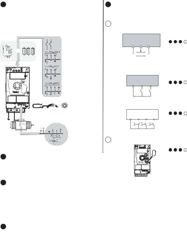
4Connect the drive: Power
•Wire the drive to the ground.
•Check circuit breaker rating or fuse rating.
•Check that the motor voltage is compatible with the drive voltage. Motor voltage ______Volts.
•Wire the drive to the motor.
•Wire the drive to the line supply.
or
ATV12 F1
ATV12 M2
ATV12 M3
0,8...1,2 N.m
7.1...10.6 lb.in
200...240V
6Apply power to the drive
•Check that used Logic Inputs are not active (see Li1, Li2, Lix ).
•Apply power to the drive.
•Drive displays bFr at first power up.
•On next start-ups, drive displays rdY .
7Set motor parameters
•See on the motor Nameplate to set the following parameters.
5 Connect the drive: Control choice
[REMOTE configuration]
5.1(Control by external reference)
•Wire the speed reference:
+5 v |
AI 1 |
COM |
Do: |
6 + 7 + 8 + 9.1 |
|
|
|
 2.2 KΩ
• Wire the command:
Control command 2-wire: Parameter tCC = 2C
LI1: forward |
ATV 12 |
|
|
LIx: reverse |
+24 V LI1 |
LIx |
Do: 6 + 7 + 8 + 9.1 |
|
Control command 3-wire:
Parameter tCC = 3C
LI1: stop |
ATV 12 |
|
|
|
|
|
Do: 6 + 7 + 8 + 9.1 |
||
LI2: forward |
+24 V LI1 |
|
LI2 |
|
|
||||
LIx: reverse |
|
LIx |
|
||||||
|
|
|
|
|
|
|
|
|
|
|
|
|
|
|
|
|
|
|
|
[LOCAL configuration]
5.2 (control by internal reference).
.
Do: 6 + 7 + 8 + 9.2
Menu |
Code |
Description |
Factory setting |
Customer |
|
setting |
|||||
|
|
|
|
||
|
bFr |
[Standard motor frequency]: |
50.0 |
|
|
COnF > FULL > |
Standard motor frequency (Hz) |
|
|||
|
|
|
|||
drC- |
nPr |
[Rated motor power]: |
drive rating |
|
|
[Motor control menu] |
Nominal motor power on motor nameplate |
|
|||
|
|
|
|||
|
nCr |
[Rated motor current]: |
drive rating |
|
|
|
Nominal motor current on motor nameplate (A) |
|
|||
|
|
|
|
8 Set basic parameters
Menu |
Code |
Description |
Factory setting |
Customer |
|
setting |
|||||
|
|
|
|
||
|
ACC |
[Acceleration]: |
3.0 |
|
|
|
Acceleration time (s) |
|
|||
|
|
|
|
||
|
dEC |
[Deceleration]: |
3.0 |
|
|
COnF |
Deceleration time (s) |
|
|||
|
|
|
|||
[CONFIGURATION] |
LSP |
[Low speed]: |
0.0 |
|
|
|
Motor frequency at minimum reference (Hz) |
|
|||
|
|
|
|
||
|
HSP |
[High speed]: |
50.0 |
|
|
|
Motor frequency at maximum reference (Hz) |
|
|||
|
|
|
|
||
www.schneider-electric.com |
|
2/4 |
S1A56146 - 05/2010 |
||
 Loading...