


Schneider Electric Powerchute Nutanix User Manual

User Guide
PowerChute™ Network Shutdown v4.3
Nutanix
990-4595F-001
01/2019

Table of Contents
Introduction ................................................................................................................................................................... 3
UPS Configuration ........................................................................................................................................................ 4
Network Configuration ............................................................................................................................................... 5
UPS Configuration Options ....................................................................................................................................... 6
Network Management Card Connection ................................................................................................................... 9
Advanced UPS Setups ............................................................................................................................................ 11
Outlet Group Registration ....................................................................................................................................... 13
Network Management Card Settings ...................................................................................................................... 14
Nutanix Configuration ................................................................................................................................................. 15
CVM/Cluster Details ................................................................................................................................................ 16
Nutanix Host Protection .......................................................................................................................................... 18
Advanced UPS configuration .................................................................................................................................. 19
Physical UPS Setup Power Protect ion .................................................................................................................... 20
Virtualization Settings .............................................................................................................................................. 22
Virtual Machine Shutdo wn and Start up ................................................................................................................... 24
Controller Virtual Machine Shutdown/Startup ......................................................................................................... 25
Acropolis File Services Shutdo wn/St ar tup .............................................................................................................. 26
Protection Domain Settings ..................................................................................................................................... 27
Cluster Shutdown/Startu p ....................................................................................................................................... 28
Virtual Machine Prioritization ................................................................................................................................... 29
Shutdown Settings ...................................................................................................................................................... 35
UPS Shutdown ........................................................................................................................................................ 36
Shutdown Command Files ...................................................................................................................................... 37
Shutdown Settings for Advanced UPS Configurations ........................................................................................... 38
SSH Settings ............................................................................................................................................................... 40
SNMP Configuration ................................................................................................................................................... 43
SNMPv1 Configuration ............................................................................................................................................ 44
SNMPv3 Configuration ............................................................................................................................................ 45
SNMP Trap Configuration ....................................................................................................................................... 46
SNMP Data Points .................................................................................................................................................. 48
Event Configuration .................................................................................................................................................... 54
Notifications ............................................................................................................................................................. 55
Event-Driven Command Files ................................................................................................................................. 56
Shutdown Actions.................................................................................................................................................... 57
Sequenced Server Shutdown ..................................................................................................................................... 58
Sample Shutdown Scenarios ...................................................................................................................................... 59
Nutanix AHV: UPS without Outlet Groups .............................................................................................................. 60
Nutanix AHV: UPS with Outlet Groups ................................................................................................................... 64

Nutanix Shutdown - Single UPS Configuration ....................................................................................................... 69
Nutanix AHV Shutdown - Advanced UPS Configuration ........................................................................................ 70
Nutanix Shutdown - VM Prioritization - Single UPS Configuration ......................................................................... 71
Nutanix Shutdown - VM Prioritization - Advanced UPS Configuration ................................................................... 72
PowerChute Events and Logging ............................................................................................................................... 73
Configurable Events ................................................................................................................................................ 74
Configurable Environmental Events ........................................................................................................................ 78
Non-Configurable Events ........................................................................................................................................ 79
Configuration (INI) File Events ................................................................................................................................ 83
SSH Action Events .................................................................................................................................................. 85
Java Update Events ................................................................................................................................................ 86
Nutanix Virtualization Events .................................................................................................................................. 87
Critical Events in a Redundant-UPS Configuration ................................................................................................. 90
General ....................................................................................................................................................................... 91
Communications Settings ....................................................................................................................................... 92
PowerChute Agents ................................................................................................................................................ 93
PowerChute Configuration File ............................................................................................................................... 94
Java Update ............................................................................................................................................................ 95
User Interface Session Timeout .............................................................................................................................. 96
Check for Updates................................................................................................................................................... 97
Customer Support ................................................................................................................................................... 98
Troubleshooting .......................................................................................................................................................... 99
Network Management Card Troubleshooting ....................................................................................................... 100
Nutanix Troubleshooting ....................................................................................................................................... 101
Browser Troubleshooting ...................................................................................................................................... 105
SSH Actions Troubleshooting ............................................................................................................................... 106
SNMP Troubleshooting ......................................................................................................................................... 107

Introduction
PowerChute Network Shutdown - Nutanix User Guide
3
TM
PowerChute
(NMC) to provide network-based shutdown of multiple computer systems.
In the case of a UPS critical event, the software performs a graceful, unattended system shutdown before the UPS
battery is exhausted. The number of protected systems is limited only by the capacity of the UPS.
View these Application Notes for detailed information on using PowerChute in specific environments.
Network Shutdown (PowerChute) works in conjunction with the UPS Network Management Card
After installation, it is essential to configure the software using the PowerChute Setup wizard.
This ensures that PowerChute is aware of UPS critical events in order to protect your system.

UPS Configuration
PowerChute Network Shutdown - Nutanix User Guide
4
This section contains information on the topics below:
• Network Configuration
• UPS Configuration Options
• Network Management Card Connection
• Advanced UPS Setups
• Outlet Group Registration
• Network Management Card Settings

Network Configuration
PowerChute Network Shutdown - Nutanix User Guide
5
PowerChute can use IPv4 or IPv6 to communicate with the Network Management Card(s).
IPv6 support is available only for Network Management Card firmware 6.0.X or higher.
Select IP
If your computer has more than one IPv4 address you will need to select one of the available addresses. The IP
address you select will be registered with the NMC and displayed in the NMC user interface under Configuration PowerChute Clients.
IPv6 Configuration
If you are using IPv6 to communicate with the NMC(s), each network adapter on your machine will typically have
several IP addresses assigned to it. Each adapter will have at least one link-local address and one global unicast
address assigned to it.
Use the Unicast IP Address drop-down box to specify which address to use. The address type selected in this
drop-down box must match the address type that you enter for the NMC(s) on the Network Management Card
Connection page. This unicast address will be registered on the NMC(s) and displayed on the PowerChute
Network Shutdown Clients page of the NMC.
fe80::88c8:3d95:bc02:74cc is an example of a link-local address.
2001:112:1:0:88c8:3d95:bc02:74cc is an example of a global unicast address.
Multicast Option
The NMC supports sending communication packets to an IPv6 Multicast address instead of sending unicast
packets to each PowerChute agent. To use this, enable the Multicast check box and enter an IPv6 Multicas t
address.
The multicast address that is entered here will be registered on the NMC(s) instead of the unicast address and
displayed on the PowerChute Network Shutdown Clients page of the NMC. The NMC(s) will send communication
packets to that multicast address.
FF02::1 is an example of a multicast address with link-local scope so that only nodes on the same
physical network segment will receive it. If using a link-local unicast address, you must use a multicast
address with link-local scope.
FF0E::1 is an example of a multicast address with global scope and the NMC will use its global unicast
address to send the packet. If using a global unicast address you must use a multicast address with global
scope.
For detailed information, please view "The Communications Process of PowerChute Network Shutdown" here.
UPS Configuration Options
PowerChute Network Shutdown - Nutanix User Guide
6
For a detailed overview of which UPS’s support each configuration, please view the “PowerChute Network
Shutdown Operating Modes and supported UPS Configurations” Application Note here.
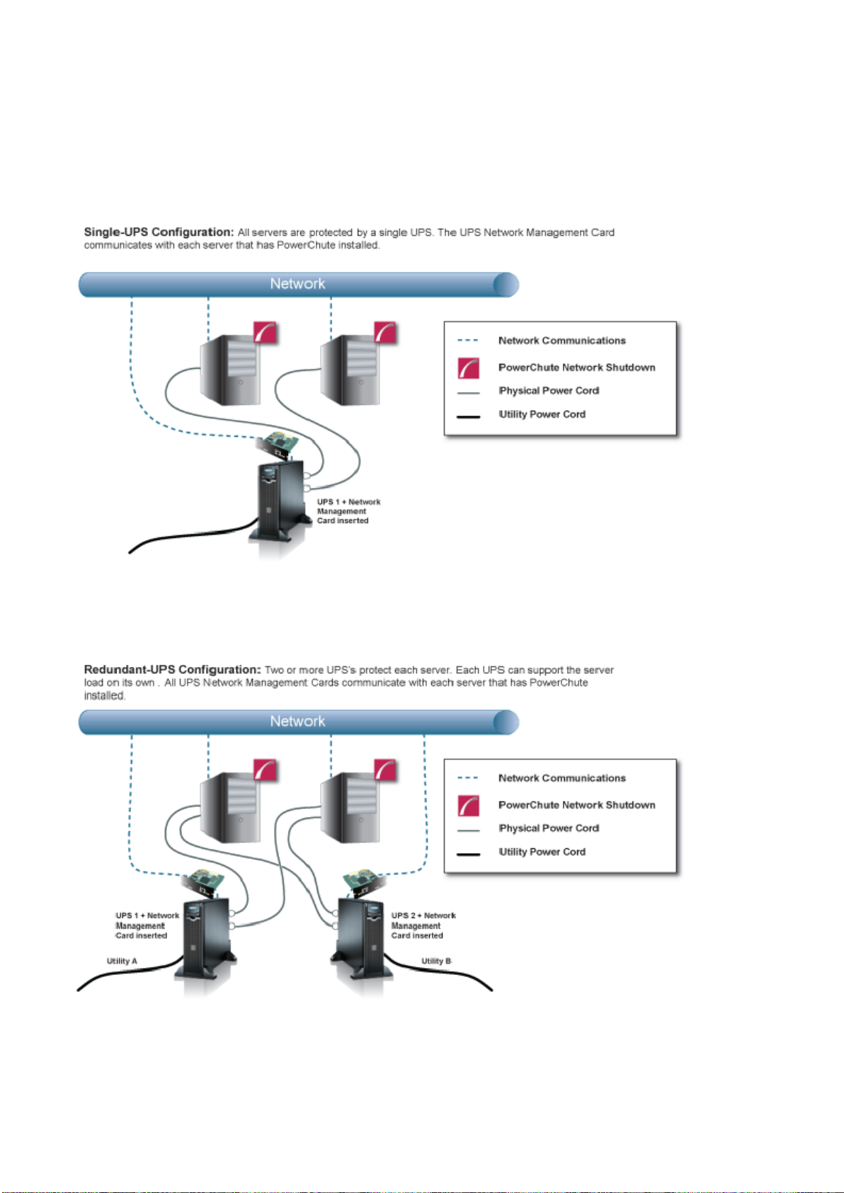
Single-UPS Configuration
Redundant-UPS Configuration
For detailed information, please view “Using PowerChute Network Shutdown in a Redundant-UPS Configuration”
Application Note here.
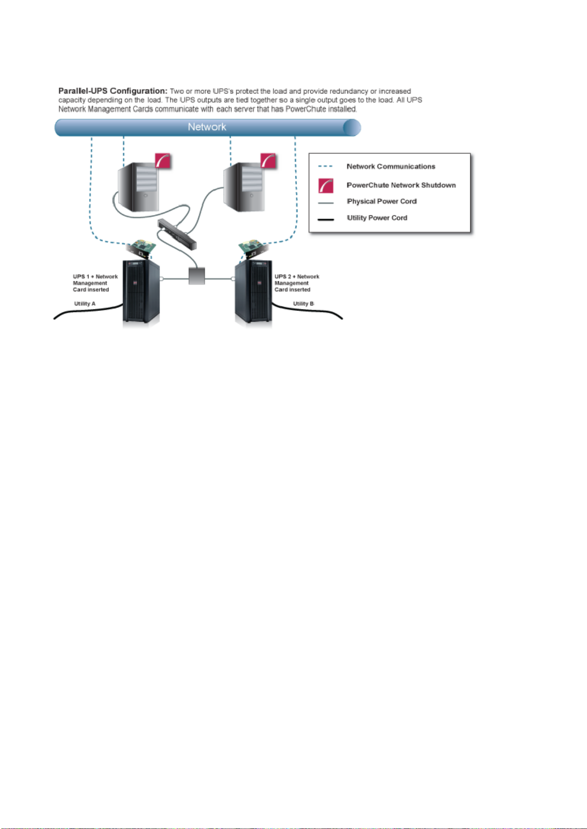
Parallel-UPS Configuration
PowerChute Network Shutdown - Nutanix User Guide
7
Note: To use the Parallel-UPS configuration, your UPS d evices must already be configured to o perate in parallel
mode.
For detailed information, please view “Using PowerChute Network Shutdown in a Parallel-UPS Configuration”
Application Note here.
PowerChute Network Shutdown - Nutanix User Guide
8
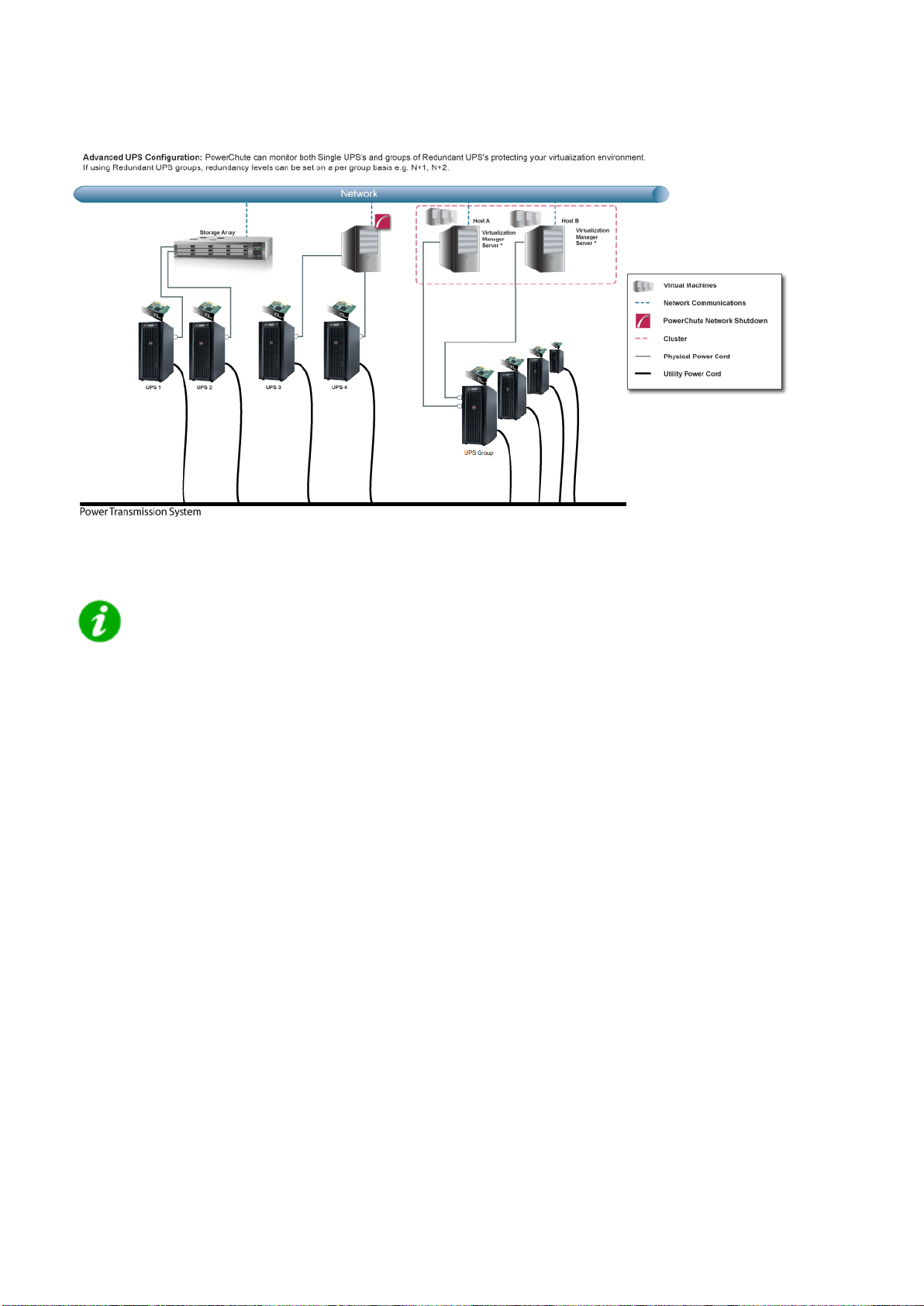
Advanced UPS Configuration
* Virtualization Manager Server is Nutanix Controller VM
In an advanced UPS configuration, all hosts in the Nutanix Cluster must be protected by the
same UPS or UPS group.
For detailed information, please view the “Using PowerChute Network Shutdown in an Advanced Redundant
Setup” Application Note here.
Network Management Card Connection
PowerChute Network Shutdown - Nutanix User Guide
9
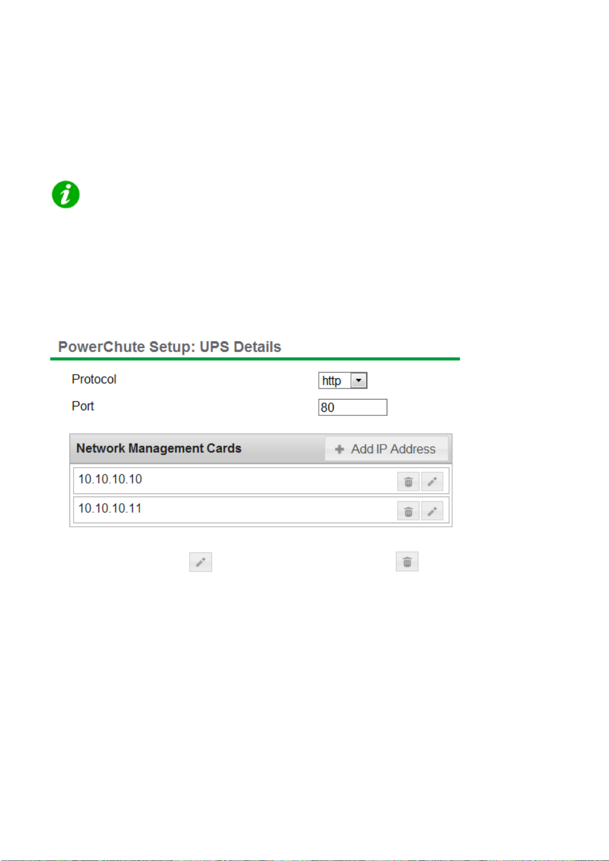
The Network Management Card uses the HTTP protocol by default. This can be changed to HTTPS through the
NMC user interface. Based on the NMC protocol used, you can select either HTTP or HTTPS in PowerChute.
The default port is 80 for HTTP, and 443 for HTTPS. Do not change this number unless you changed the port being
used by your NMC.
The NMC uses a self-signed SSL certificate by default when HTTPS is enabled. You need to
enable "Accept Untrusted SSL Certificates" to allow PowerChute to establish communication
with the NMC if a self-signed cert is being used by the NMC.
For Redundant and Parallel configurations, you need to enter more than one IP address to enable
communications with all the relevant NMCs.
For more information on UPS configurations and supported UPS models, view the Application Note "PowerChute
Network Shutdown Operating Modes and supported UPS Configurations" here.
Add each IP address using the + Add IP Address button. Enter the IP address of the NMC in the UPS. Click OK.
To edit an IP address, click the icon. To delete an IP address, click the icon.
Adding a Trusted Certificate to PowerChute for NMC communication
When using the HTTPS protocol to communicate with the NMC, you must select the Accept Untrusted SSL
Certificates? check box. However, it is possible to create a Trusted Certificate file and add it to the PowerChute
truststore.
Your NMC Security Handbook has details on the Security Wizard used to create the Trusted Certificate file with an
extension .CRT. This file is then used to create components that can be uploaded to the NMC to replace the default
self-signed certificate.
In order to facilitate the trusted SSL communication of PowerChute with the NMC, this Trusted Certificate file must
then be added to the system Java cacerts keystore or to the PowerChutekeystore file. (You can do this using the
Java keytool.exe; for details see the Java help documentation). Adding it to the cacerts keystore means it is
available to all your applications as distinct from just PowerChute.

By default the PowerChute-keystore file is located in APC\PowerChute\group1. Its password is “password”. If you
PowerChute Network Shutdown - Nutanix User Guide
10
add the Trusted Certificate and you subsequently get a connection error with the NMC, then it could be because a)
the certificate has expired, b) it is not yet valid, or c) it has been revoked. In any of these cases, you need to add a
new Trusted Certificate to the PowerChute server or to upload a new valid SSL certificate to the NMC.
The PowerChute-keystore file only exists after the first attempt is made to communicate with
the NMC using HTTPS (by using the configuration wizard for example). For this reason, for a
silent installation you must add the Trusted Certificate to the Java cacerts keystore.
PowerChute only checks the keystore when its service starts. After you add the Trusted
Certificate, you will need to re-start the PowerChute service if it’s already running.
Advanced UPS Setups
PowerChute Network Shutdown - Nutanix User Guide
11
Add UPS Setup
In an Advanced UPS configuration, a single instance of PowerChute Network Shutdown can monitor multiple UPS
setups and initiate graceful shutdown of equipment based on different redundancy levels. Each setup can be a
single UPS or a UPS group. A single UPS setup is represented by the icon. A UPS group is represented by the
icon.
For example, one setup may be a group of UPS's that are configured with N+2 redundancy. Another setup may be
a single UPS.
On the UPS Details page of the Setup Wizard, click the + Add UPS(s) button to create a new setup.
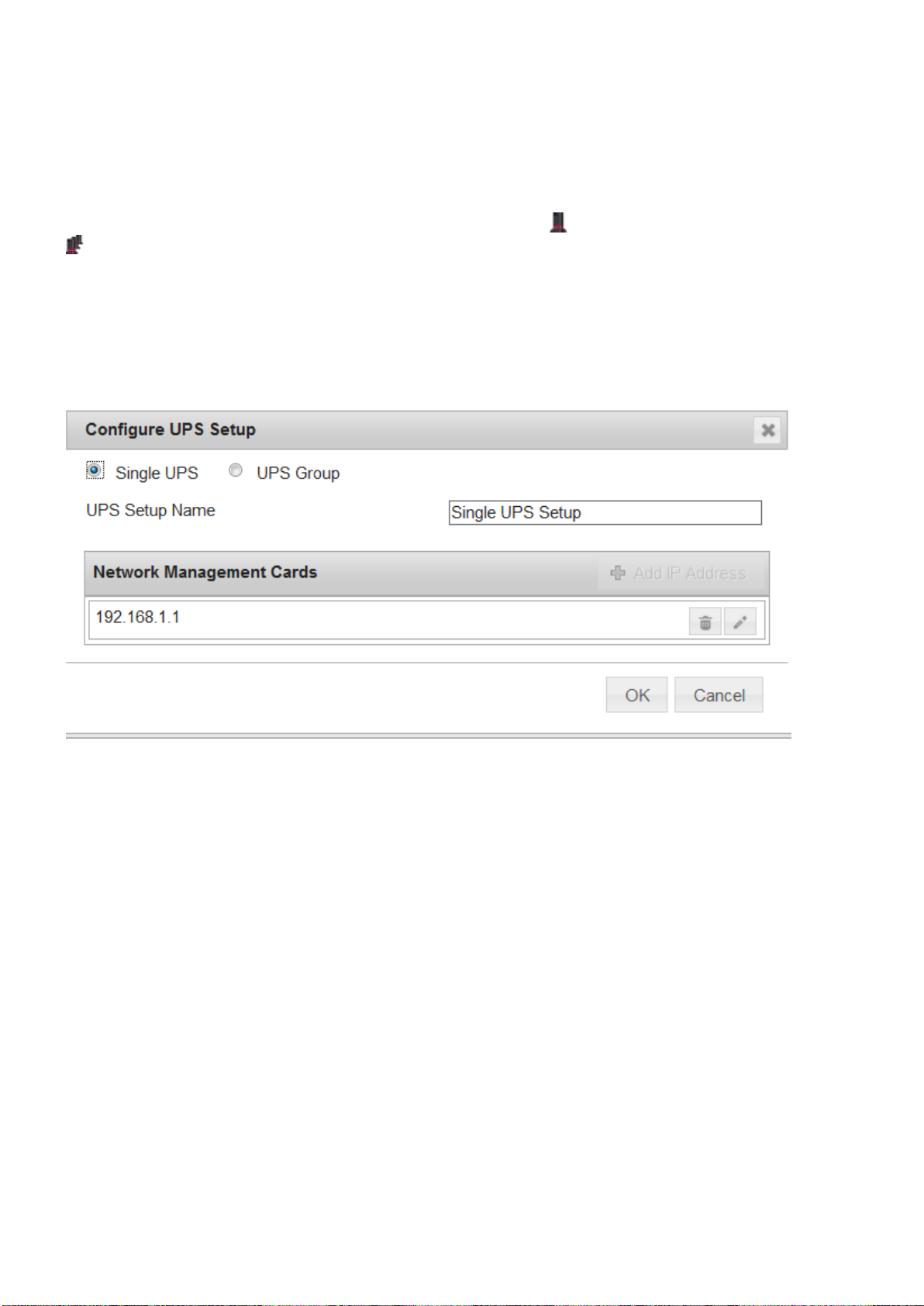
To create a setup with a single UPS, on the Configure UPS Setup dialog choose Single UPS:
1. Enter a UPS Setup Name (with a maximum of 20 ASCII characters)
2. Click the + Add IP Address button and enter the IP address of the Network Management card in the UPS.
Click OK.
3. Click OK to complete Single UPS Setup.
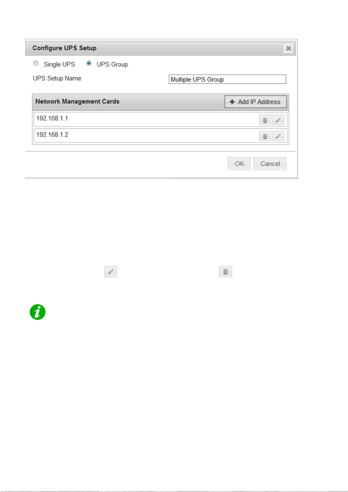
To create a setup with a group of UPS devices, choose UPS Group:
PowerChute Network Shutdown - Nutanix User Guide
12
1. Enter a UPS Setup Name (with a maximum of 20 ASCII characters)
2. Click the + Add IP Address button and enter the IP address of the Network Management card in the UPS.
Click OK.
3. Repeat for each of the UPS devices to be added to the UPS group. A minimum of 2 IP addresses is
required to set up a UPS Group.
4. Click OK to complete Group UPS Setup.
Repeat for each UPS setup required.
To edit a UPS Setup, click the icon. To delete a UPS setup, click the icon.
Click the Next button to go to the next step of the Setup Wizard.
PowerChute has been tested with a total of 16 NMCs in an advanced configuration. However it
is possible to configure for more than 16 NMCs in this configuration.
For detailed information, please view the “Using PowerChute Network Shutdown in an Advanced Redundant
Setup” Application Note here.

Outlet Group Registration
PowerChute Network Shutdown - Nutanix User Guide
13
If your UPS supports outlet groups you must specify which one the server is being powered by so that PowerChute
can monitor it for shutdown events and also issue turn-off commands to that outlet group.
It is not supported to map UPS outlet groups when PowerChute is configured with Nutanix.
UPS Shutdown Behavior in Mixed UPS Environments
If your servers are being powered by a mix of outlet-aware UPS’s (e.g. SMX/ SMT) and non-outlet-aware UPS’s
(e.g. SU/ SUA) in a Redundant UPS Configuration, PowerChute only provides the option to turn off the UPS and
not the outlet group.
Your servers are still protected if there is a UPS critical event or if the outlet group is commanded to shut down e.g.
via the NMC User Interface.
Network Management Card Settings
PowerChute Network Shutdown - Nutanix User Guide
14
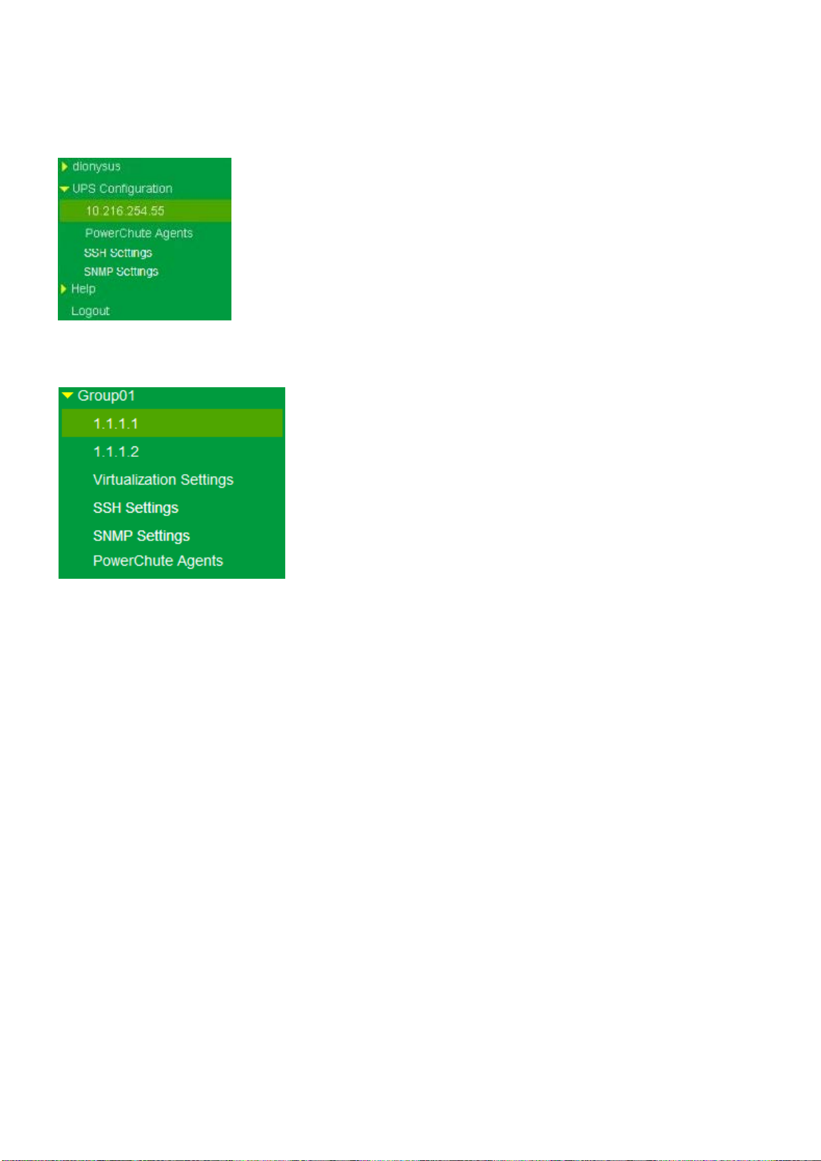
For Single, Redundant and Parallel UPS configurations, the IP address of each NMC that PowerChute is
communicating with is displayed under the UPS Configuration menu option.
For Advanced UPS configuration, each UPS Setup is displayed as a menu item and the IP address of the NMC(s)
with which PowerChute is communicating is displayed under each UPS setup.
Click on the IP address to view the UPS information specific to that NMC.
UPS information displayed includes:
• NMC IP Address
• UPS model name
• UPS configuration
The NMC Host Name from the NMC's DNS settings page under Network - DNS - Configur a tio n is also disp la yed .
This is not the same as the UPS name that can be set under Configuration - UPS General on the NMC.
Clicking the Launch button opens the NMC user interface.
Nutanix Configuration
PowerChute Network Shutdown - Nutanix User Guide
15
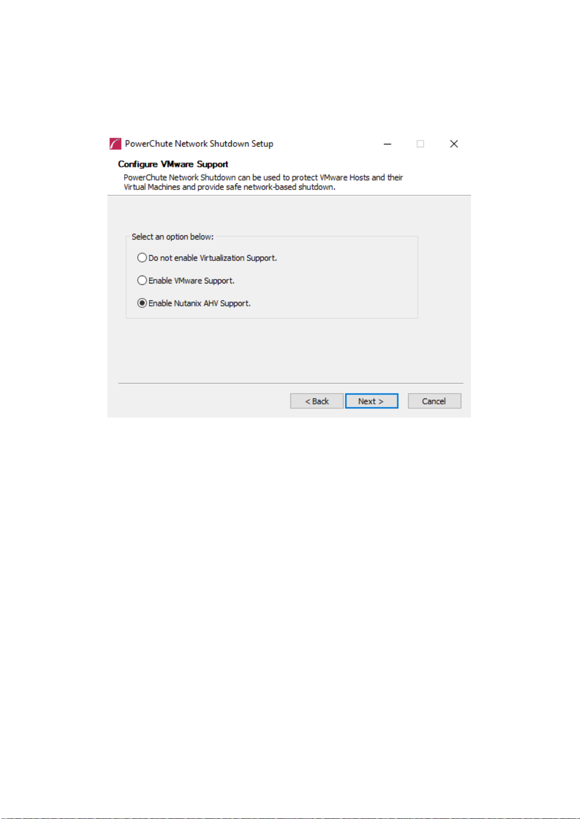
To enable Nutanix™ support configuration options in the PowerChute Setup wizard, Enable Nutanix AHV
Support must be selected during the installation.
For more information on configuring PowerChute with Nutanix, see the PowerChute Installation Guide, available on
the APC website.

CVM/Cluster Details
PowerChute Network Shutdown - Nutanix User Guide
16
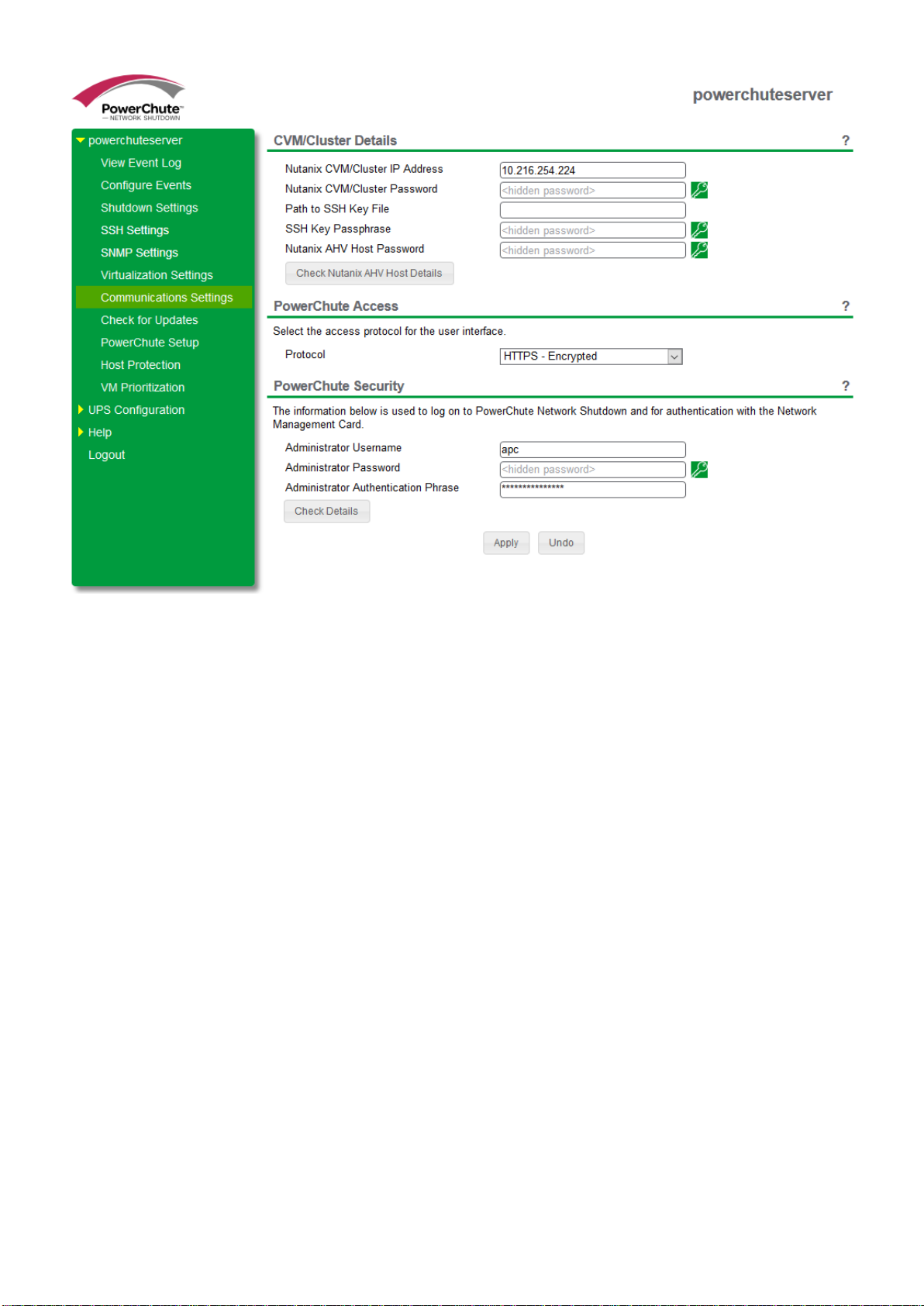
This screen appears in the PowerChute Setup wizard and the details entered here are used to connect to your
Nutanix Controller Virtual Machine (CVM) or Cluster. The recommended configuration is to connect to your Nutanix
Cluster.
You can authenticate the connection to your CVM or Cluster using the following options:
• Enter your CVM/Cluster IP address, CVM/Cluster password and AHV Host password. Both passwords
must be set to connect to your CVM/Cluster. If the Nutanix AHV Host Password field is left blank in the
PowerChute Setup wizard, the CVM/Cluster password specified will be copied to this field.
• Enter your CVM/Cluster IP address, the SSH key file path and its passphrase, if available.
These connection settings can be edited later through the PowerChute UI in the Communication Settings screen.
It may be necessary to install the Java Cryptography Extension Policy Files before you can
connect to a Nutanix Cluster that requires a 256-bit cipher.
For more information, see Knowledge Base article FA361427 available on the APC websi te.
If both authentication options are specified in the PowerChute Setup wizard, PowerChute will
use the passwords to connect to the CVM/Cluster.
NOTE: You must use the "nutanix" user account credentials to connect to the Cluster/CVM.
You cannot use the "admin" user account credentials to connect.
In the Communication Settings screen in the PowerChute UI, if you wish to change your authentication method,
PowerChute will erase your previous authentication details. For example, if you connected to your Nutanix Cluster
using the passwords option in the PowerChute Setup wizard and you want to use a SSH key file instead, when the
Path to SSH Key File field is edited and the changes are applied, PowerChute will erase your configured
passwords.
If you are authenticating the connection to your CVM/Cluster using passwords, you can use the Check Nutanix
AHV Host Details button in the UI to check if your AHV hosts are online and accessible.
NOTES:
• If you do not specify a Nutanix AHV Host Password in the PowerChute Setup wizard,
this field will be set to the password specified for Nutanix CVM/Cluster Password.
• If you specify a Nutanix AHV Host Password, you must click the Apply button before
you can check to see if your AHV hosts are online.
CV
PowerChute Network Shutdown - Nutanix User Guide
17
M/Cluster Details
Nutanix Host Protection
PowerChute Network Shutdown - Nutanix User Guide
18
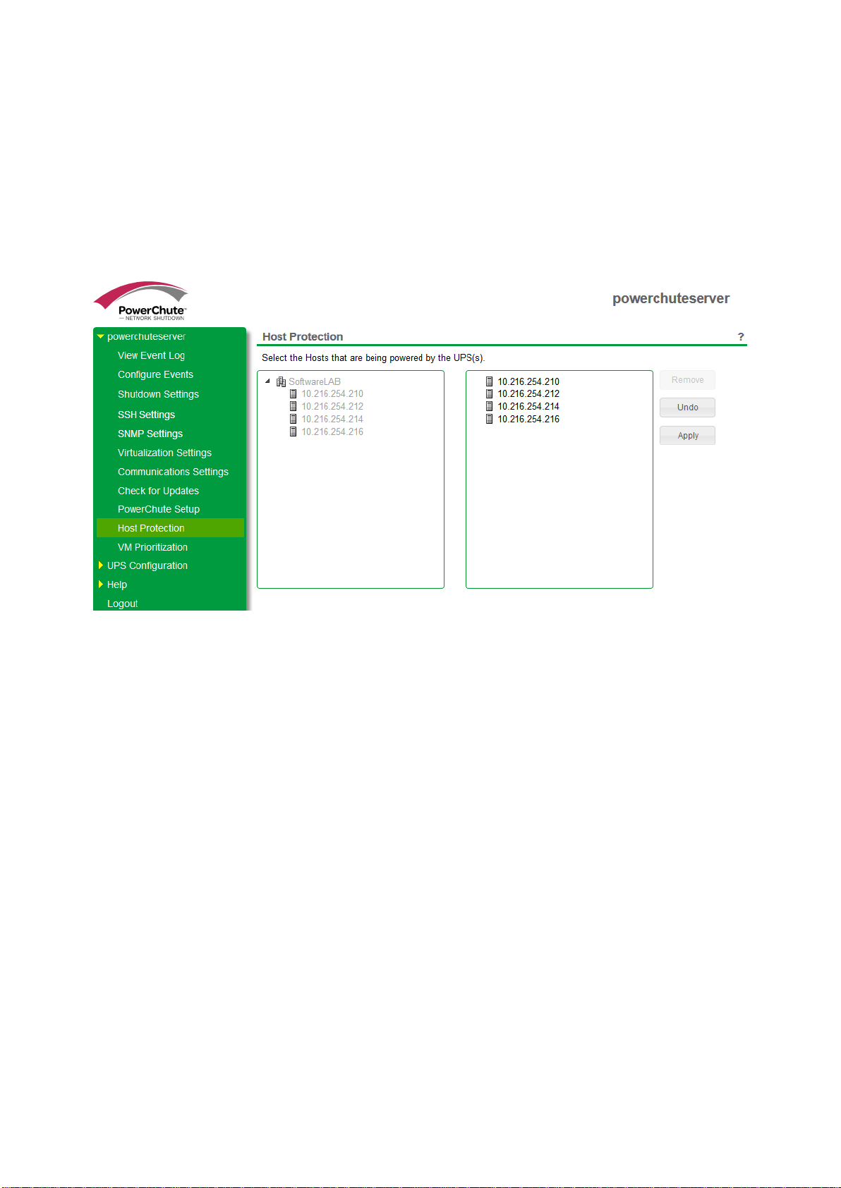
Once connected to the Nutanix Cluster, PowerChute displays all of the Nutanix hosts in the inventory in a tree view.
From this screen you can select the hosts that PowerChute should protect.
Single, Redundant, and Parallel-UPS configurations
Specify the hosts in the left-hand panel you want to protect by dragging them to the right-hand panel of this scr een.
Each host listed in the left-hand panel must be added to the right-hand panel of this screen before you can proceed
with your configuration.
When a critical UPS event occurs, PowerChute will shut down hosts in the order that they appear in the right-hand
panel. You can change this order by clicking on a host in the right-hand panel and dragging it up and down.
Advanced UPS configur a tio n
PowerChute Network Shutdown - Nutanix User Guide
19
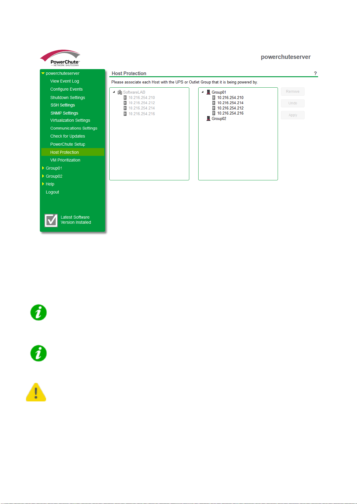
Advanced UPS configuration
In an advanced UPS configuration, the Nutanix hosts are powered separately by one or more UPS device(s) in a
UPS Setup. The right-hand panel shows the UPS Setups that have been configured and are monitored by
PowerChute. You need to associate each Nutanix host in the left-hand panel with the UPS by which it is powered.
To do this, drag each host to the UPS/UPS group in the right-hand panel.
In an advanced UPS configuration, all hosts in the Nutanix Cluster must be protected by the
same UPS or UPS group.
For this configuration, PowerChute must be installed on a physical Windows machine outside
the Cluster.
If the IP address/Hostname of any of the hosts are changed, it will be necessary to re-associate
the hosts with the UP S de vic es .
Physical UPS Setup Power Protection
PowerChute Network Shutdown - Nutanix User Guide
20
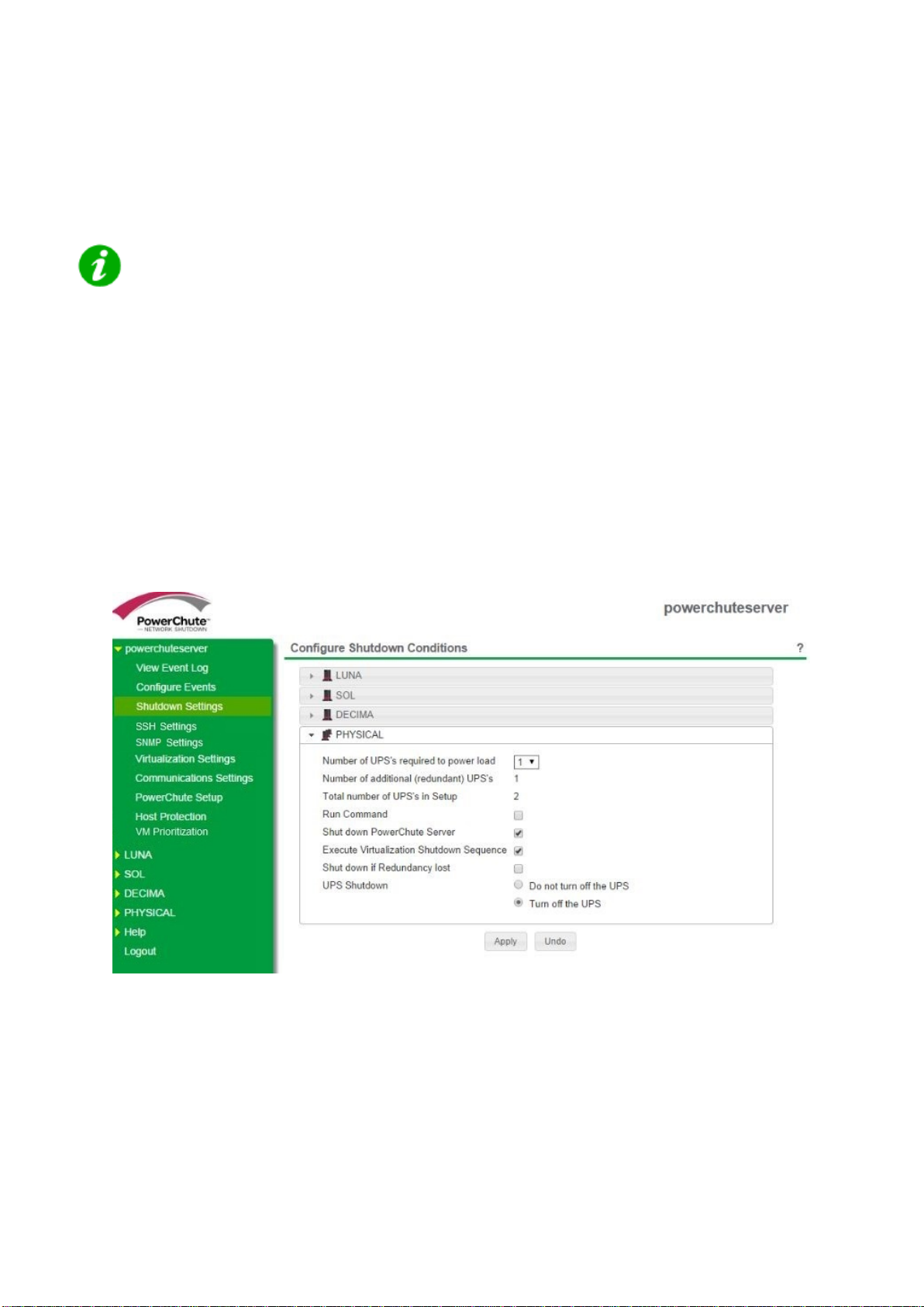
In Advanced UPS Setups, PowerC hut e can m onitor U PS de vices which ar e po wer ing equ ipment outside a Nutanix
Cluster (e.g. a Storage Array Device or a physical server machine running PowerChute).
For more information see Shutdown Settings for Advanced UPS Setups.
On the Host Protection page, do not link Nutanix hosts with the UPS devices that are
powering the physical equipment.
The following additional options will then be displayed on the Shutdown Settings page:
• Shutdown PowerChute Server - This is enabled by default and is used to gracefully shut down the
physical machine running PowerChute. This option can be disabled if the UPS is powering a Storage Array
Device.
• Execute Virtualization Shutdown Sequenc e - This triggers a shutdown sequence using the actions
configured on the Virtualization Settings page. This option should be enabled for all UPS Setups that are
powering physical equipment.
PowerChute User Interface - Configure Shutdown Conditions
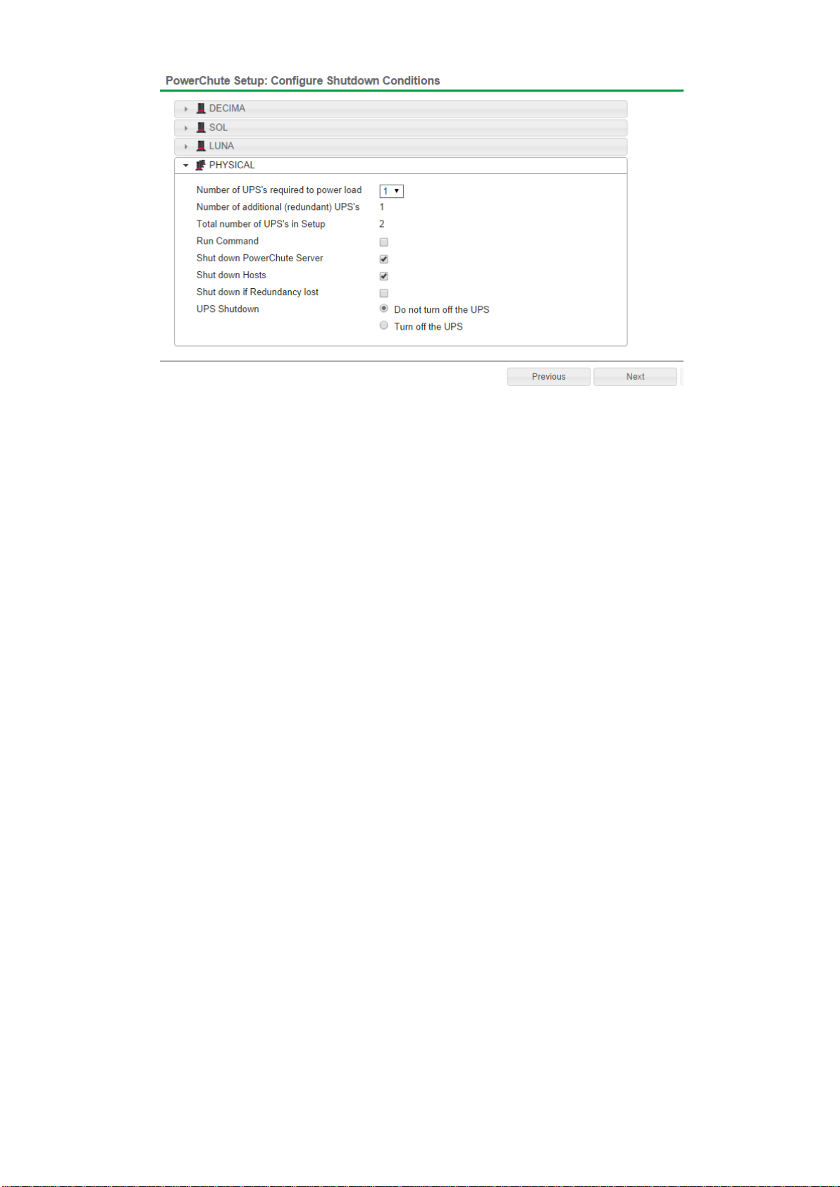
werChute Setup - Configure Shutdown Conditions
PowerChute Network Shutdown - Nutanix User Guide
21
Po
Virtualization Settings
PowerChute Network Shutdown - Nutanix User Guide
22
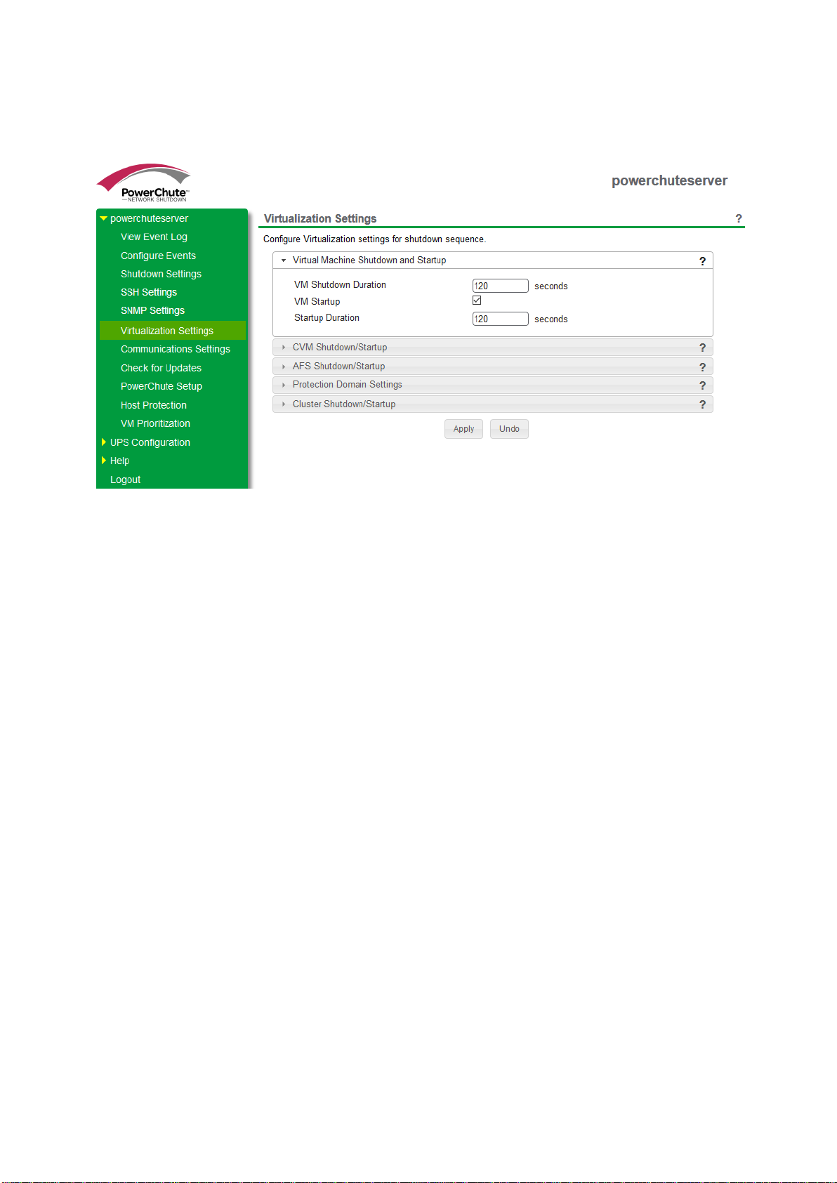
Virtual machine (VM) settings like VM Shutdown, Controller VM (CVM) Shutdown, and Cluster Shutdown can be
configured in the Virtualization Settings screen.
Virtualization Settings
For more information see:
• Virtual Machine Shutdown/Startup
• Controller Virtual Machine Shutdown/Startup
• Acropolis File Services Shutdo wn/St ar tup
• Cluster Shutdown/Startu p
Virtualization Settings in Advanced UPS Configuration
In an advanced UPS configuration, settings entered on this page will be applied to all UPS Setups if the Apply
Virtualization Settings to all UPS Setups checkbox is selected. This checkbox is enabled by default.
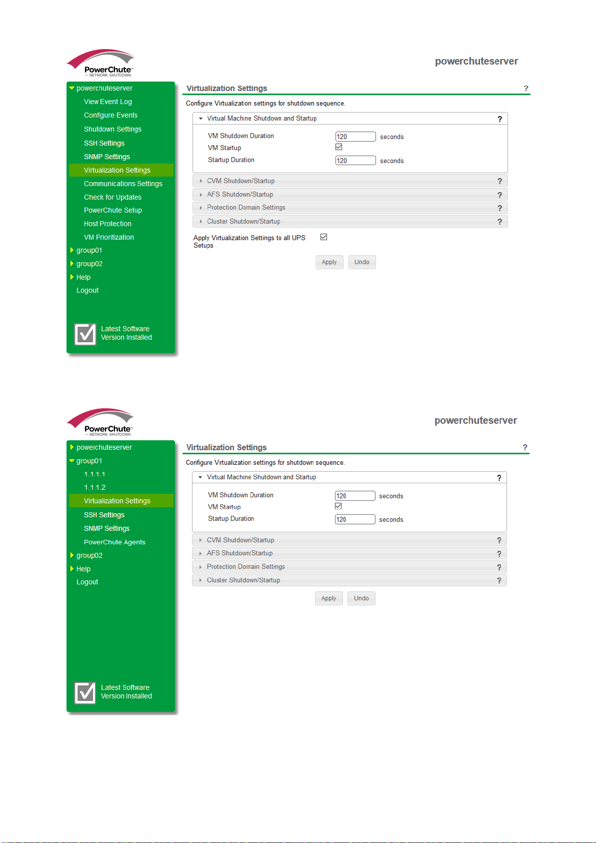
you have applied settings to individual UPS Setups, you should uncheck this option to prevent them from being
PowerChute Network Shutdown - Nutanix User Guide
23
If
overwritten.
Individual UPS Setup Settings applied
Virtual Machine Shutdown and Startup
PowerChute Network Shutdown - Nutanix User Guide
24
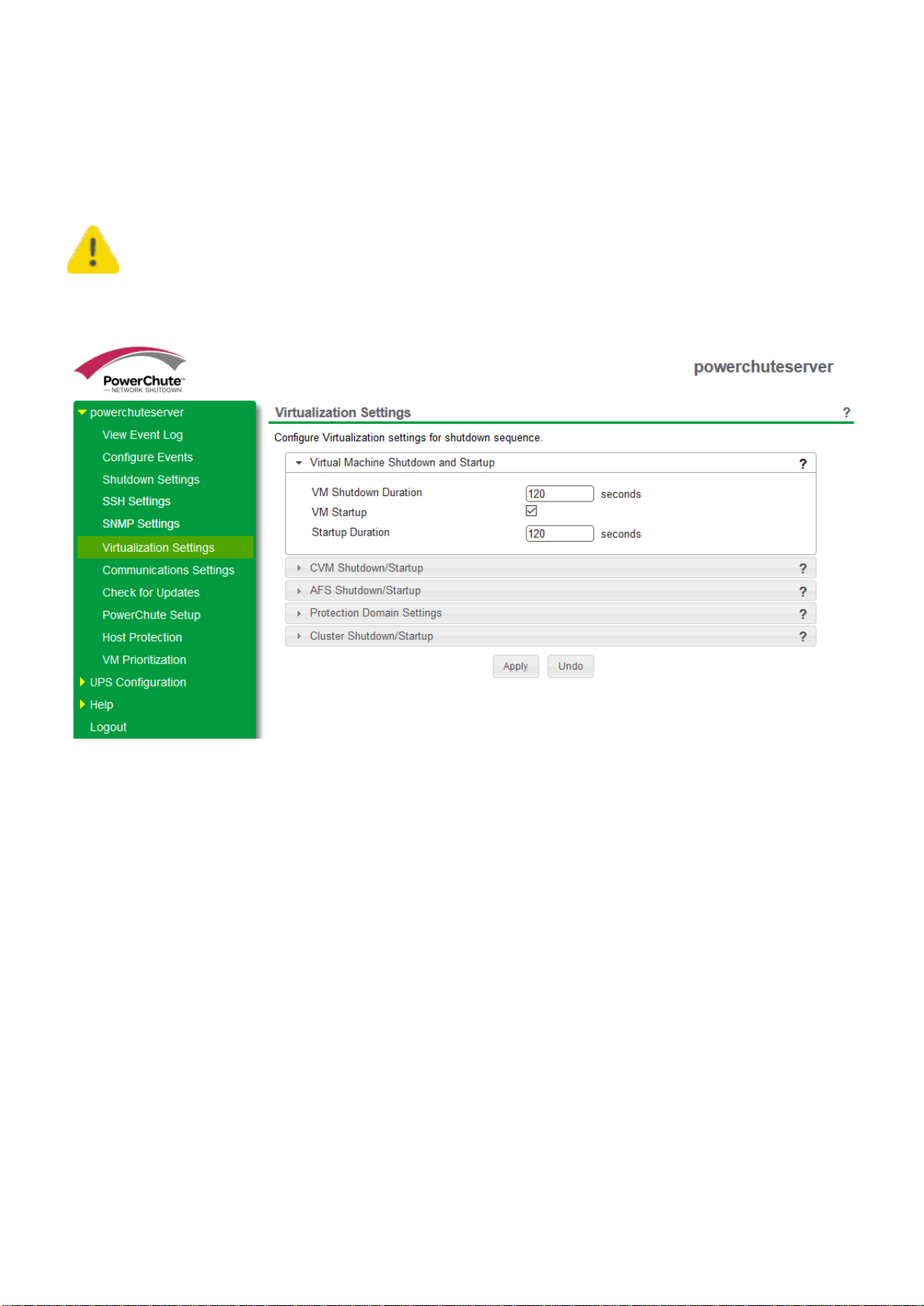
The Duration field is the time allowed for all the VMs to gracefully shut down (User VMs, AFS VMs and Controller
VMs are not included). If the VMs are shut down before the Duration time, PowerChute waits until this time has
elapsed before proceeding to the next step in the sequence.
Using the Duration field, you must allow sufficient time for all your VMs to gracefully shut down
before the hosts are commanded to shut down.
VM shutdown unsuccessful
When PowerChute issues a VM shutdown command, PowerChute will use the time specified in the Shutdown
Duration field to allow VMs to gracefully shut down. If VM shutdown is unsuccessful, PowerChute logs the
"Nutanix User VMs cannot be gracefully shut down. Powering off UVMs." event in the Event Log and will attempt to
power off the VMs. PowerChute will wait 15 seconds to power off the VMs, and if this is unsuccessful, they will be
forced off. PowerChute will wait an additional 15 seconds to force off the VMs, and if they cannot be forced off,
PowerChute logs the "Insufficient time configured to shut down VMs on Cluster [Cluster]." event.
The 15 seconds durations PowerChute uses to power off and force off your VMs are taken from the configuration
file.
Re-starting after a shutdown
Selecting the VM Startup checkbox re-starts any VMs that were shut down when a UPS critical event has been
resolved and the Nutanix Hosts are powered on. PowerChute first checks that all hosts are available, all CVMs are
running and the Cluster is available before starting the VMs.
If VMs are in the process of being started when a critical event occurs, PowerChute waits for the Duration time to
elapse before shutting down VMs. This is to ensure that the VMs are shut down gracefully.

Controller Virtual Machine Shutdown/Startup
PowerChute Network Shutdown - Nutanix User Guide
25
A Controller Virtual Machine (CVM) runs on each node in a Nutanix block and is responsible for running the
Nutanix Cluster. CVM Shutdown is enabled by default. In the PowerChute shutdown sequence, the CVM is shut
down after all other VMs in the Cluster, and the Nutanix Cluster itself are shut down.
The Duration field is the time allowed for all the CVMs to gracefully shut down. If the CVMs are shut down before
the Duration time, PowerChute waits until this time has elapsed before proceeding to the next step in the
sequence.
Using the Shutdown Duration field, you must allow sufficient time for all your CVMs to gracefully
shut down before the hosts are commanded to shut down.
CVM Shutdown/Startup
Re-starting after a shutdown
Selecting the CVM Startup checkbox re-starts any CVMs that were shut down when a UPS critical event has been
resolved and the Nutanix Hosts are powered on. PowerChute first checks that the host is available.
If CVMs are in the process of being started when a critical event occurs, PowerChute waits for the Duration time to
elapse before shutting down CVMs. This is to ensure that the CVMs are shut down gracefully.
It is recommended to wait at least 5 minutes after CVM startup to ensure all services are running
before re-starting the Cluster. You should account for this using the Startup Duration field.

Acropolis File Services Shutdown/Startup
PowerChute Network Shutdown - Nutanix User Guide
26
The AFS Shutdown checkbox is enabled by default, and this option should be left enabled to allow graceful
Cluster shutdown. In the event of a shutdown, PowerChute stops the AFS service, which shuts down the AFS VMs.
This step occurs after the User VMs are gracefully shut down.
The Duration field is the time allowed for the AFS service and VMs to gracefully shut down and start up following a
UPS critical event.
Using the Duration field, you must allow sufficient time for all your AFS VMs to gracefully shut
down. If the AFS VMs are not shut down, this may prevent the Cluster and CVMs from shutting
down.
AFS Shutdown/St ar tu p
Re-starting after a shutdown
Selecting the AFS Startup checkbox re-starts the AFS service, which also powers on any AFS VMs that were shut
down when a UPS critical event has been resolved and the Nutanix Hosts are powered on.
If the AFS VMs are in the process of being started when a critical event occurs, PowerChute waits for the Duration
time to elapse before shutting down the VMs. This is to ensure that the VMs are shut down gracefully.
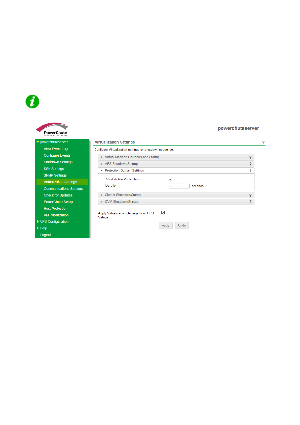
Protection Domain Settings
PowerChute Network Shutdown - Nutanix User Guide
27
A protection domain is a collection of VMs that are backed up or replicated on a schedule to recover data. The
Abort Active Replications checkbox is enabled by default, and this option should be enabled if your protection
domain is configured to replicate on a schedule.
If enabled, PowerChute will wait the time specified in the Duration field before aborting any active protection
domain replications in the event of a critical UPS event.
NOTE: The Duration field will only be taken into consideration if there are active replications
when PowerChute reaches this step in the shutdown sequence. If there are no active
replications this duration will not be included in the shutdown sequence.
Protection Domain Settings
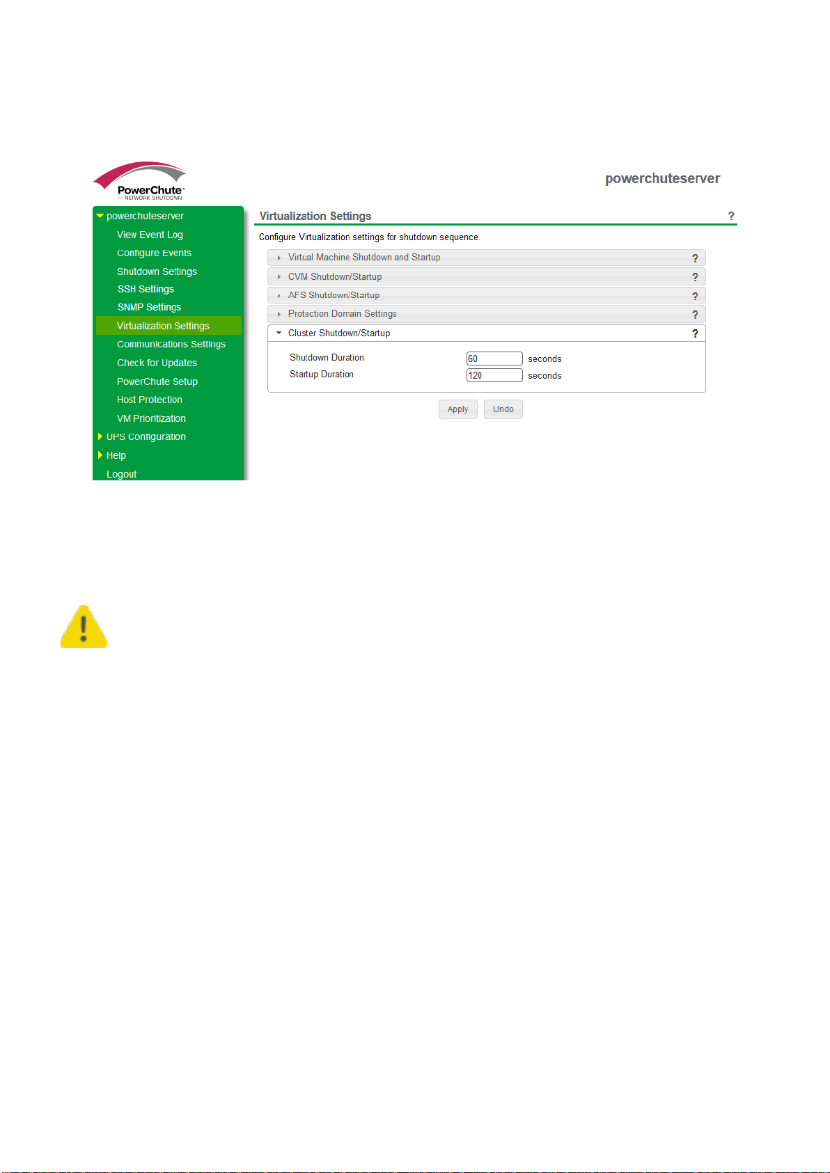
Cluster Shutdown/Startup
PowerChute Network Shutdown - Nutanix User Guide
28
Cluster Shutdown occurs after PowerChute has completed the previous steps in the shutdown sequence: User VM
Shutdown, AFS Shutdown, and abor t act ive re plic ati on s .
Cluster Shutdown/Startu p
If the Cluster is shut down before the Duration time, PowerChute waits until this time has elapsed before
proceeding to the next step in the sequence (shutting down the physical PowerChute hos t) .
Using the Shutdown Duration field, you must allow sufficient time for your Cluster to gracefully
shut down before the physical PowerChute host is commanded to shut down.
Re-starting after a shutdown
The time specified in the Startup Duration field will be the time, in seconds, PowerChute will wait after issuing the
Cluster start command before proceeding with the next steps in the startup sequence. The Cluster is re-started
after the CVMs are powered on.
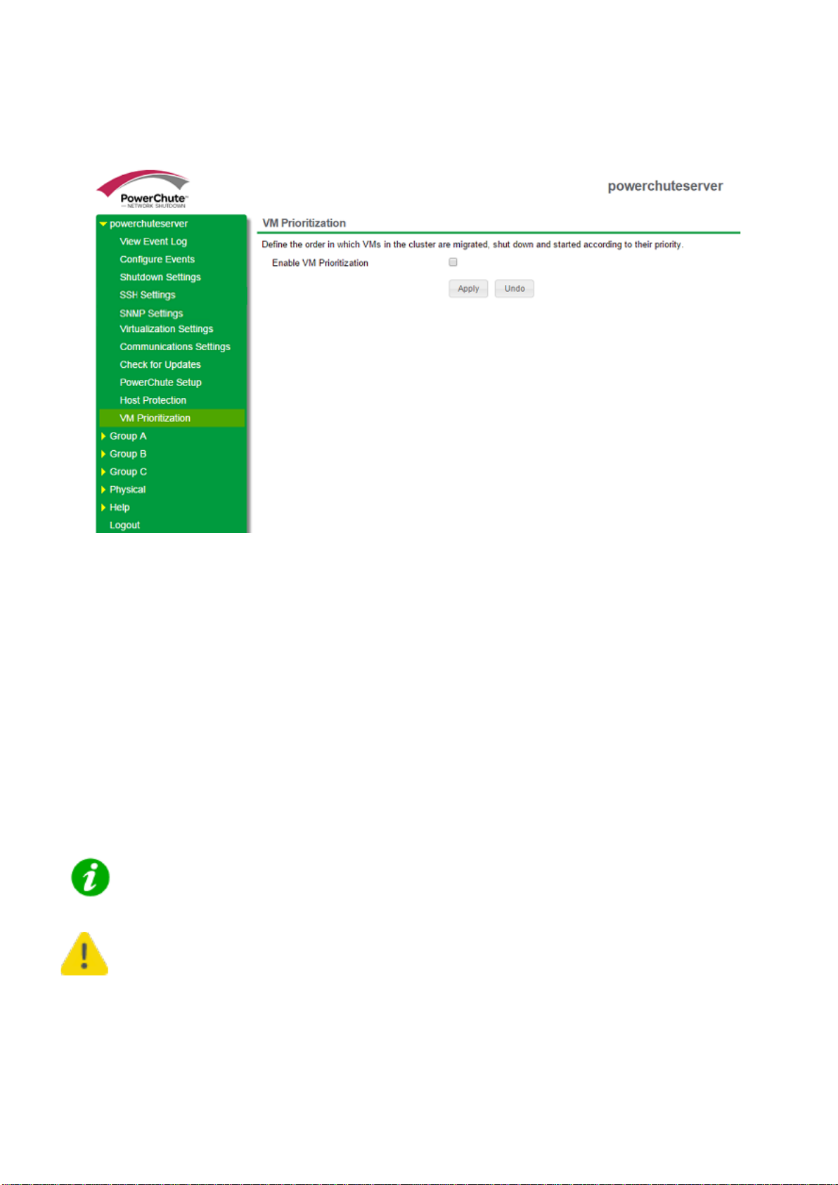
Virtual Machine Prioritization
PowerChute Network Shutdown - Nutanix User Guide
29
Use Virtual Machine Prioritization settings to specify the order in which VMs shut down and power on. VM
Prioritization is configured in the main PowerChute interface and is disabled by default.
Enable VM Prioritization screen
To enable VM Prioritization, select the Enable VM Prioritization checkbox. Three options display:
• Prioritize VMs
• Set VM Shutdown Duration
• Set VM Startup Duration
Prioritize VMs
Virtual Machines can be grouped into five priority groups – High, Medium, Low, Group 1 and Group 2. When VM
Prioritization is enabled, an inventory view of the datacenter, clusters, and VMs appears on the left. On the right,
the High, Medium, Low, Group 1 and Group 2 priority groups are listed.
NOTE: CVMs and AFS VMs are not displayed and cannot be added to a priority group.
For PowerChute to correctly identify Clusters and VMs, their names must be unique. It is not
supported to have more than one VM with the same VM name.
 Loading...