


 Loading...
Altivar 71
Communication parameters
User manual
Software V2.7
11/2009 |
1755861
www.schneider-electric.com

Contents
Document structure and directions for use __________________________________________________________________________ 5 Presentation _________________________________________________________________________________________________ 7 Software enhancements________________________________________________________________________________________ 9 Enhancements made to version V1.2 in comparison to V1.1 _____________________________________________________ 9 Enhancements made to version V1.6 in comparison to V1.2 ____________________________________________________ 10 Enhancements made to version V2.5 in comparison to V1.6 ____________________________________________________ 10 Enhancements made to version V2.7 in comparison to V2.5 ____________________________________________________ 10 Notations___________________________________________________________________________________________________ 11 Description of parameters _______________________________________________________________________________ 11 Drive terminal displays __________________________________________________________________________________ 11
Profiles ____________________________________________________________________________________________________ 12 What is a profile? ______________________________________________________________________________________ 12 Functional profiles supported by the Altivar 71 _______________________________________________________________ 13 I/O profile __________________________________________________________________________________________________ 14 Definition ____________________________________________________________________________________________ 14 Control word - run on state [2 wire] (2C) ____________________________________________________________________ 16 Control word - run on edge [3 wire] (3C) ___________________________________________________________________ 17 Status word (ETA) _____________________________________________________________________________________ 18 Example: I/O profile with positioning by sensors function _______________________________________________________ 19
CiA402 profile _______________________________________________________________________________________________ 21 Functional description __________________________________________________________________________________ 21 CiA402 state chart _____________________________________________________________________________________ 22 Description of states ___________________________________________________________________________________ 23 Control word (CMD) ____________________________________________________________________________________ 25 Status word (ETA) _____________________________________________________________________________________ 27 Starting sequence _____________________________________________________________________________________ 28 Sequence for a drive powered by the power section line supply __________________________________________________ 29 Sequence for a drive with separate control section ____________________________________________________________ 31 Sequence for a drive with line contactor control ______________________________________________________________ 34
Command/reference switching __________________________________________________________________________________ 37 Channels ____________________________________________________________________________________________ 37 Not separate mode ____________________________________________________________________________________ 38 Separate mode _______________________________________________________________________________________ 38 Switching in not separate mode ___________________________________________________________________________ 39 Switching in separate mode ______________________________________________________________________________ 39 Channel switching _____________________________________________________________________________________ 40 Reference switching principle ____________________________________________________________________________ 42 Command switching principle ____________________________________________________________________________ 43 Assigning control word bits ______________________________________________________________________________ 44 Example: I/O profile with positioning by sensors function _______________________________________________________ 47 Copy on switching _____________________________________________________________________________________ 49
Forced local ________________________________________________________________________________________________ 50 Definition ____________________________________________________________________________________________ 50 Forced local mode and reference switching _________________________________________________________________ 51 Forced local mode and command switching _________________________________________________________________ 52 Priority stops________________________________________________________________________________________________ 54 Priority stops on the graphic display terminal ________________________________________________________________ 54 Priority stops via the terminals or the network ________________________________________________________________ 54 Communication monitoring_____________________________________________________________________________________ 56 Principle _____________________________________________________________________________________________ 56 Network monitoring criteria ______________________________________________________________________________ 56 Behavior in the event of a network fault _____________________________________________________________________ 57 Detailed operation _____________________________________________________________________________________ 58 Assignment of setpoints from a network___________________________________________________________________________ 60 Setpoint parameters ___________________________________________________________________________________ 60 Without PID regulator __________________________________________________________________________________ 61 With PID regulator _____________________________________________________________________________________ 62
Configuration saving and switching ______________________________________________________________________________ 63 Saving the configuration ________________________________________________________________________________ 63 Restore configuration ___________________________________________________________________________________ 65 Configuration switching via control word ____________________________________________________________________ 66 Configuration switching by selection _______________________________________________________________________ 70
Parameter set switching _______________________________________________________________________________________ 72 Loading drive parameters______________________________________________________________________________________ 77 Requirement _________________________________________________________________________________________ 77 Procedure ___________________________________________________________________________________________ 77 Command parameters ________________________________________________________________________________________ 79 Setpoint parameters __________________________________________________________________________________________ 82
1755861 |
11/2009 |
3 |

Sommaire
Status parameters ___________________________________________________________________________________________ 84 Output value parameters ______________________________________________________________________________________ 92 Output values (speed) __________________________________________________________________________________ 92 Output values (torque) __________________________________________________________________________________ 93 Output values (motor) __________________________________________________________________________________ 94 Reference parameters ________________________________________________________________________________________ 96 References (speed) ____________________________________________________________________________________ 96 References (torque) ____________________________________________________________________________________ 97 Reference (regulator) ___________________________________________________________________________________ 98 Measurement parameters______________________________________________________________________________________ 99 Input measurements ___________________________________________________________________________________ 99 Thermal states ________________________________________________________________________________________ 99 Time _______________________________________________________________________________________________ 100
I/O parameters _____________________________________________________________________________________________ 102 Logic I/O ___________________________________________________________________________________________ 102 Analog inputs ________________________________________________________________________________________ 103 Analog outputs _______________________________________________________________________________________ 104 Encoder ____________________________________________________________________________________________ 105
Fault parameters____________________________________________________________________________________________ 106 Log parameters_____________________________________________________________________________________________ 113 Log of the following faults ______________________________________________________________________________ 117 Identification parameters _____________________________________________________________________________________ 121 CiA402 standard configuration and adjustment parameters___________________________________________________________ 124 ODVA standard configuration and adjustment parameters ___________________________________________________________ 128 Index of parameters codes ____________________________________________________________________________________ 129
4 |
1755861 |
11/2009 |

Document structure and directions for use
Installation Manual
This manual describes:
•Assembly
•How to connect the drive
Programming Manual
This manual describes:
•Functions
•Parameters
•How to use the drive's display terminal (integrated display terminal and graphic display terminal)
Communication Parameters Manual
This manual describes:
•The operating modes specific to communication (state chart)
•The interaction between communication and local control
•The control, reference and monitoring parameters, with specific information for use via a bus or communication network
It does not include the drive adjustment and configuration parameters, which are contained in the Excel file supplied as an appendix to this manual.
All the parameters are grouped together in an Excel file supplied as an appendix, with the following data:
-Code
-Name
-Addresses: logic, CANopen, INTERBUS, Device Net
-Category
-Read/write access
-Type: signed numerical, unsigned numerical, etc.
-Unit
-Factory setting
-Minimum value
-Maximum value
-Display on the graphic display terminal and the 7-segment integrated display terminal
-Relevant menu
This file offers the option of sorting and arranging the data according to any criterion chosen by the user.
Data relating to operation, interdependences and limits of use are described in the Programming Manual. The various documents are to be used as follows:
1.For information about the drive and its programming, refer to the Programming Manual.
2.For information about communication and its programming, refer to the Parameters Manual.
3.Use the Parameters file to define any addresses and values of the adjustment and configuration parameters to be modified through communication.
The section entitled "Loading drive parameters" on page 77 describes the recommended procedure for loading parameters through communication.
Modbus, CANopen, Ethernet, Profibus, INTERBUS, Uni-Telway, FIPIO, Modbus Plus and Device Net manuals
These manuals describe:
•Assembly
•Connection to the bus or network
•Diagnostics
•Configuration of the communication-specific parameters via the integrated display terminal or graphic display terminal
They describe the protocol communication services in detail.
"Controller Inside" Manual
This manual describes, for the "Controller Inside" card:
•Assembly
•Connection
•Functions
•Configuration
1755861 |
11/2009 |
5 |

Documentation structure
Altivar 58/58F Migration Manual
This manual describes the differences between the Altivar 71 and the Altivar 58/58F.
It explains how to replace an Altivar 58 or 58F, including how to replace drives communicating on a bus or network.
Note: This Parameters Manual describes the parameters of the Altivar 71 profiles. It does not describe the Altivar 58/58F compatibility parameters (SE8 profile).
These are detailed in the Altivar 58/58F Communication Variables Manual and the Migration Manual.
Altivar 78 Migration Manual
This manual describes the differences between the Altivar 71 and the Altivar 78.
It explains how to replace an Altivar 78.
6 |
1755861 |
11/2009 |
Presentation
Magelis XBT Premium
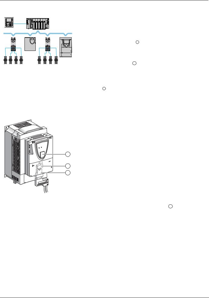
The Altivar 71 drive has been designed to meet all the configuration requirements encountered within the context of industrial communication installations.
It includes Modbus and CANopen communication protocols as standard.
FTM |
FTM |
Two integrated communication ports enable direct access to the Modbus protocol: |
|
• |
One RJ45 Modbus connector port 2 , located on the drive front panel, |
||
|
|
|
which is used to connect: |
|
ATV 31 |
|
• The remote graphic display terminal |
|
|
• A Magelis industrial HMI terminal |
|
|
ATV 71 |
|
|
|
|
• The PowerSuite software workshop |
|
Sensors |
Sensors |
• |
One RJ45 Modbus network port 1 , located on the drive’s control terminals, |
|
which is dedicated to control and signaling by a PLC or other type of controller. |
||
Example of configuration on the CANopen bus |
|
||
|
It can also be used to connect a display terminal or the PowerSuite software |
||
|
|
|
workshop. |
|
|
The CANopen protocol can be accessed from the Modbus network port via the |
|
|
|
CANopen adapter 3 (1). |
|
|
|
The Altivar 71 can also be connected to other networks and industrial communication |
|
|
|
buses by using one of the communication option cards: |
|
•Ethernet TCP/IP
•Modbus/Uni-Telway. This card provides access to additional functions, which complement those of the integrated ports: Modbus ASCII and 4-wire RS 485
•Fipio
|
• |
Modbus Plus |
|
• |
Profibus DP |
|
• |
DeviceNet |
|
• INTERBUS |
|
|
• etc. (Please refer to the catalog) |
|
|
The |
control section can be powered separately, thus allowing communication |
2 |
(monitoring, diagnostics) to be maintained even if the power supply section fails. |
|
|
The main communication functions of Altivar 58 and Altivar 58F drives are compatible |
|
1 |
with the Altivar 71 (2): |
|
3 |
- Connection |
|
- Communication services |
||
- Drive behavior (profile)
- Control and monitoring parameters - Basic adjustment parameters
The PowerSuite software workshop supports the transfer of configurations from
Altivar 58 and Altivar 58F drives to the Altivar 71.
(1) If the CANopen adapter is installed, Modbus will not be available on the network port 1 .
(2) Please refer to the ATV 58(F)/ATV 71 Migration Manual supplied on the documentation CD-ROM.
1755861 |
11/2009 |
7 |

Presentation
All the drive functions are accessible via the network:
•Control
•Monitoring
•Adjustment
•Configuration
If the "Controller Inside" programmable card is installed on the drive, its variables (%MW, etc.) can be accessed via the integrated Modbus ports or the Ethernet option card.
The speed/torque command and reference can come from different sources:
•The I/O terminals
•The communication network
•The "Controller Inside" programmable card
•The remote graphic display terminal
•The PowerSuite software workshop (for commissioning and maintenance)
The Altivar 71 drive's advanced functions can be used to manage switching of these command and reference sources according to application requirements.
The periodic communication variables can be selected via:
•The network configuration software (Sycon, etc.): CANopen, DeviceNet
•The Altivar 71’s communication scanner function: Profibus DP, Fipio, Modbus Plus
•The network's IO Scanner function: Ethernet TCP/IP
With the exception of DeviceNet, regardless of network type, the Altivar 71 can be controlled:
•In accordance with the Drivecom profile (CANopen CiA DSP 402)
•In accordance with the I/O profile, whereby control is as straightforward and flexible as control via the I/O terminals The DeviceNet card supports the ODVA standard profile.
Communication is monitored according to criteria specific to each protocol. Regardless of protocol type, the reaction of the drive to a communication fault can be configured:
•Drive fault involving: Freewheel stop, stop on ramp, fast stop or braked stop
•Stop without drive fault
•Maintain the last command received
•Fallback position at a predefined speed
•Ignore the fault
A command from the CANopen bus is handled with the same priority as an input from the drive terminals. This enables very good response times to be achieved on the network port via the CANopen adapter.
8 |
1755861 |
11/2009 |

Software enhancements
Since the Altivar ATV71 was first launched, it has benefited from the addition of several new functions. Software version has now been updated to V2.7. The new version can be substituted to the previous versions without making any changes.
Although this documentation relates to version V2.7, it can still be used with previous versions, as the updates merely involves the addition of new values and parameters. None of the previous versions parameters have been modified or removed.
The software version is indicated on the nameplate attached to the body of the drive.
Enhancements made to version V1.2 in comparison to V1.1
Factory setting
Note 1: In version V1.1, the analog input was 0 ± 10 V. For safety reasons, this input is configured as 0 + 10 V in the new version. Note 2: In version V1.1, the analog output AO1 was assigned to the motor frequency. In the new version, this output is not assigned.
Except for these two parameters, the factory setting of version V1.1 is retained in the new version. The new functions are inactive in the factory setting.
Motor frequency range
The maximum output frequency range is extended from 1000 to 1600 Hz (depending on rating and selected control profile).
New parameters and functions
[1.2 MONITORING] (SUP-) menu
Addition of states and internal values relating to the new functions described below.
[1.3 SETTINGS] (SEt-) menu
•[High torque thd.] (ttH)
•[Low torque thd.] (ttL)
•[Pulse warning thd.] (FqL)
•[Freewheel stop Thd] (FFt)
[1.4 MOTOR CONTROL] (drC-) menu
•[rpm increment] (InSP)
•Extension to all drive ratings of the following configurations, formerly limited to 45 kW for ATV71pppM3X and 75 kW for ATV71pppN4: synchronous motor [Sync. mot.] (SYn), sinus filter [Sinus filter] (OFI), noise reduction [Noise reduction] (nrd), braking balance [Braking balance] (bbA).
[1.5 INPUTS / OUTPUTS CFG] (I-O-) menu
•Input AI1 becomes configurable as 0 + 10 V or 0 ± 10 V using [AI1 Type] (AI1t).
•[AI net. channel] (AIC1)
•New options for assigning relays and logic outputs: rope slack, torque greater than high threshold, torque less than low threshold, motor rotating in forward direction, motor rotating in reverse, measured speed threshold attained, and load variation detection.
•Analog output AO1 becomes usable as a logic output and can be assigned to the relay and logic output functions.
•New option of modifying the scaling of the analog outputs using the parameters [Scaling AOx min] (ASLx) and [Scaling AOx max] (ASHx).
•New options for assigning analog outputs: signed motor torque and measured motor speed.
•New options for assigning alarm groups: rope slack, torque greater than high threshold, torque less than low threshold, measured speed threshold attained, and load variation detection.
1755861 |
11/2009 |
9 |

Software enhancements
[1.7 APPLICATION FUNCT.] (Fun-) menu
•The summing, subtraction and multiplier reference functions become assignable to the network analog input [Network AI] (AIU1)
•New parameter [Freewheel stop Thd] (FFt) used to adjust a threshold for switching to freewheel at the end of a stop on ramp or fast stop.
•New parameter: Brake engage at controlled zero speed [Brake engage at 0] (bECd).
•The weight sensor [Weight sensor ass.] (PES) becomes assignable to the network analog input [Network AI] (AIU1).
•New "rope slack" function, with the parameters [Rope slack config.] (rSd) and [Rope slack trq level] (rStL).
•Use of the ramp [Acceleration 2] (AC2) during PID function starts and wake-ups.
•Torque limitation [TORQUE LIMITATION] (tOL-) becomes configurable as a % or 0.1% using [Torque increment] (IntP) and can be assigned to the network analog input [Network AI] (AIU1).
•New "stop at calculated distance after end of slowdown travel" function, with the parameters [Stop distance] (Std), [Rated linear speed] (nLS) and [Stop corrector] (SFd).
•Positioning by sensor or limit switch [POSITIONING BY SENSORS] (LPO-) becomes configurable as positive or negative logic using [Stop limit config.] (SAL) and [Slowdown limit cfg.] (dAL).
•Parameter switching [PARAM.] (MLP-) becomes assignable to attained frequency thresholds [Freq. Th. attain.] (FtA) and [Freq. Th. 2 attain.] (F2A).
•New half floor function: [HALF FLOOR] (HFF-) menu.
[1.8 FAULT MANAGEMENT] (FLt-) menu
•Option of reinitializing the drive without switching it off, using [Product reset] (rP).
•Option of reinitializing the drive using a logic input without switching it off, using [Product reset assig.] (rPA).
•Option of configuring the "output phase loss" fault [Output Phase Loss] (OPL) to [Output cut] (OAC) is extended to all drive ratings (formerly limited to 45 kW for ATV71pppM3X and 75 kW for ATV71pppN4).
•The external fault [EXTERNAL FAULT] (EtF-) becomes configurable as positive or negative logic using [External fault config] (LEt).
•New monitoring function by speed measurement via the "Pulse input", using the [FREQUENCY METER] (FqF-) menu.
•New load variation detection function, using the [DYNAMIC LOAD DETECT.] (dLd-) menu.
•The braking unit short-circuit fault becomes configurable using [Brake res. fault Mgt] bUb).
[7 DISPLAY CONFIG.] menu
•Addition in [7.4 TERMINAL ADJUSTMENT] of the [CONTRAST] and [STANDBY] parameters for adjusting the contrast of the graphic display unit and setting it to standby.
Enhancements made to version V1.6 in comparison to V1.2
Extension of the range with addition of the drives ATV71pppY for network 500 to 690 V.
There are no new parameters, but the ranges of adjustment and factory settings of some parameters are adapted to the new voltage.
[1.5 INPUTS / OUTPUTS CFG] (I-O-) menu
Increase in adjustment range of delay parameters for relays and logic outputs : 0 to 60000 ms instead of 0 to 9999 ms.
Enhancements made to version V2.5 in comparison to V1.6
[1.3 SETTINGS] (SEt-) menu
•New parameters [Skip Frequency] (JPF), [Skip Frequency 2] (JF2) and [3rd Skip Frequency] (JF3) allow to avoid critical speed which generate resonances.
•New parameter [Skip.Freq.Hysteresis] (JFH) to adjust the range of skip frequency.
•Possibility to adjust the parameter [Torque ratio] (trt) (visible too in [TORQUE CONTROL] (tOr-) menu).
Important :
For V2.5 version, the behaviour of the following functions is different from the previous when type of stop "freewheel" is selected (factory value):
•[LIMIT SWITCHES] (LSt-) function,
•[POSITIONING BY SENSORS] (LPO-) function,
•"shutdown" command by communication (see CiA402 state chart in communication parameters manual). Actually, on previous versions, type of stop "freewheel" was not well done.
Enhancements made to version V2.7 in comparison to V2.5
[7 DISPLAY CONFIG.] menu
Addition in [7.4 KEYPAD PARAMETERS] of [Power up menu]. This parameter allows to choose the menu which displays on the drive on power up.
[1.3 SETTINGS] (SEt-) menu
The adjustment range of [Time to restart] (ttr) can now be configured between 0.00 and 15.00 seconds.
10 |
1755861 |
11/2009 |

Notations
Description of parameters
Identification
A parameter is defined by means of various character strings:
•Code: 4 characters max. The code makes it possible to identify the parameter on the integrated 7-segment display terminal (Examples: brt, tLIG)
•Name: Description in plain text (used by the PowerSuite software workshop)
•Terminal name: Character string in square brackets for the graphic display terminal [Gen. torque lim]
Addresses
There are 4 formats for specifying parameter addresses:
•Logic address: Address for the Modbus messaging (RS485 and Ethernet TCI/IP) and the PKW indexed periodic variables (Fipio, Profibus DP), in decimal and hexadecimal (preceded by 16#).
To optimize Modbus messaging performance, two addresses are given for the control word and the status word. The addresses annotated "speed" are for use in rpm; the addresses annotated "frequency" are for use in Hz.
•CANopen index: CANopen index/subindex in hexadecimal format, to be used for variable assignment of PDOs and SDO messaging
•INTERBUS index: Index/subindex in hexadecimal for PCP messaging
•DeviceNet path: Class/instance/attribute in hexadecimal
Read/write
•R: Read only
•R/W: Read and write
•R/WS: Read and write, but write only possible when motor is at standstill
Type
•WORD (bit register): Word where each bit represents an item of command, monitoring or configuration information
•WORD (listing): Word where each value represents a possible choice for a configuration or state
•INT: Signed integer
•UINT: Unsigned integer
•DINT: Signed double integer
•UDINT: Unsigned double integer
Format
Hexadecimal values are written as follows: 16#pppp
Drive terminal displays
The menus that appear on the graphic display terminal are shown in square brackets. Example: [1.9 COMMUNICATION].
The menus that appear on the integrated 7-segment display terminal always end with a dash and appear between round brackets. Example: (COM-).
Parameter names are displayed on the remote graphic display terminal in square brackets. Example: [Fallback speed].
The parameter codes displayed on the integrated 7-segment display terminal are shown in round brackets. Example: (LFF).
1755861 |
11/2009 |
11 |
Profiles
What is a profile?
There are three types of profile:
•Communication profiles
•Functional profiles
•Application profiles
Communication profiles
A communication profile describes the characteristics of the bus or network:
•Cables
•Connectors
•Electrical characteristics
•Access protocol
•Addressing system
•Periodic exchange service
•Messaging service
•...
A communication profile is unique to a type of network (Fipio, Profibus DP, etc.) and is used by various different types of device.
Functional profiles
A functional profile describes the behavior of a type of device. It defines:
•Functions
•Parameters (name, format, unit, type, etc.)
•Periodic I/O variables
•State chart(s)
•...
A functional profile is common to all members of a device family (variable speed drives, encoders, I/O modules, displays, etc.).
Ideally, functional profiles should be network-independent, but in reality they are not. They can feature common or similar parts. The standardized (IEC 61800-7) functional profiles of variable speed drives are:
•CiA402
•PROFIDRIVE
•CIP
DRIVECOM has been available since 1991.
CiA402 "Device profile for drives and motion control" represents the next stage of this standard’s development and is maintained by Can In Automation.
Some protocols also support the ODVA (Open DeviceNet Vendor Association) profile.
Application profiles
Application profiles define in their entirety the services to be provided by the devices on a machine. For example, "CiA DSP 417-2 V 1.01 part 2: CANopen application profile for lift control systems - virtual device definitions".
Interchangeability
The aim of communication and functional profiles is to achieve interchangeability of the devices connected via the network. Although this aim is not always achieved, the profiles facilitate free competition.
12 |
1755861 |
11/2009 |

Profiles
Functional profiles supported by the Altivar 71
I/O profile
Using the I/O profile simplifies PLC programming.
When controlling via the terminals or the display terminal, the I/O profile is used without knowing it.
With an Altivar 71, the I/O profile can also be used when controlling via a network.
The drive starts up as soon as the run command is sent.
The 16 bits of the control word can be assigned to a function or a terminal input.
This profile can be developed for simultaneous control of the drive via:
•The terminals
•The Modbus control word
•The CANopen control word
•The network card control word
•The "Controller Inside" control word
The I/O profile is supported by the drive itself and therefore in turn by all the communication ports (integrated Modbus, CANopen and the Ethernet, Fipio, ModbusPlus, Modbus, Uni-Telway, Profibus DP, DeviceNet, and INTERBUS communication cards).
CiA402 profile
The drive only starts up following a command sequence. The control word is standardized.
5 bits of the control word (bits 11 to 15) can be assigned to a function or a terminal input.
The CiA402 profile is supported by the drive itself and therefore in turn by all the communication ports (integrated Modbus, CANopen and the Ethernet, Fipio, ModbusPlus, Modbus, Uni-Telway, Profibus DP, DeviceNet, and INTERBUS communication cards).
The Altivar 71 supports the CiA402 profile’s "Velocity mode".
In the CiA402 profile, there are two modes that are specific to the Altivar 71 and characterize command and reference management (see section “Command/reference switching”, page 37):
•Separate mode [Separate] (SEP)
•Not separate mode [Not separ.] (SIM)
ODVA profile
The drive starts up as soon as the run command is sent.
The control word is standardized.
The ODVA profile is supported by the DeviceNet communication card.
1755861 |
11/2009 |
13 |
I/O profile
Definition
The behavior of the drive is identical whether via the network or via the terminals.
The I/O profile is achieved via the following configuration:
Menu |
Parameter |
Value |
|
|
|
[1.6 - COMMAND] (CtL-) |
[Profile] (CHCF) |
[I/O profile] (IO) |
|
|
|
As well as to logic inputs of the terminals, drive functions can be assigned to control word bits. A function input can be assigned to:
•A terminal input (LI2 to LI14)
•A Modbus control word bit (C101 to C115)
•A CANopen control word bit (C201 to C215)
•A network card control word bit (C301 to C315)
•A Controller Inside control word bit (C401 to C415)
•A switched bit (Cd00 to Cd15): See "Command/reference switching" section.
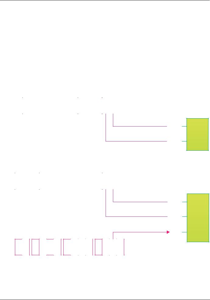
Schematic diagrams:
Fixed assignment on CANopen:
CANopen control word
bit 15 |
bit 14 |
bit 13 |
bit 12 |
|
bit 11 |
bit 10 |
bit 9 |
bit 8 |
|
bit 7 |
bit 6 |
bit 5 |
bit 4 |
|
bit 3 |
bit 2 |
bit 1 |
bit 0 |
|
|
|
|
|
|
|
|
|
|
|
|
|
|
|
|
|
|
|
Function
 C201 A
 C202 B
Fixed assignment to terminals and on CANopen: :
CANopen control word
bit 15 |
bit 14 |
bit 13 |
bit 12 |
|
bit 11 |
bit 10 |
bit 9 |
bit 8 |
|
bit 7 |
bit 6 |
bit 5 |
bit 4 |
|
bit 3 |
bit 2 |
bit 1 |
bit 0 |
|
|
|
|
|
|
|
|
|
|
|
|
|
|
|
|
|
|
|
Function
|
|
|
|
|
|
Terminals |
|
|
|
|
|
|
|
LI14 |
LI13 |
LI12 |
LI11 |
LI10 |
LI9 |
LI8 |
LI7 |
LI6 |
LI5 |
LI4 |
LI3 |
LI2 |
LI1 |
 C201 A
 C202 B
LI2 C
14 |
1755861 |
11/2009 |
I/O profile
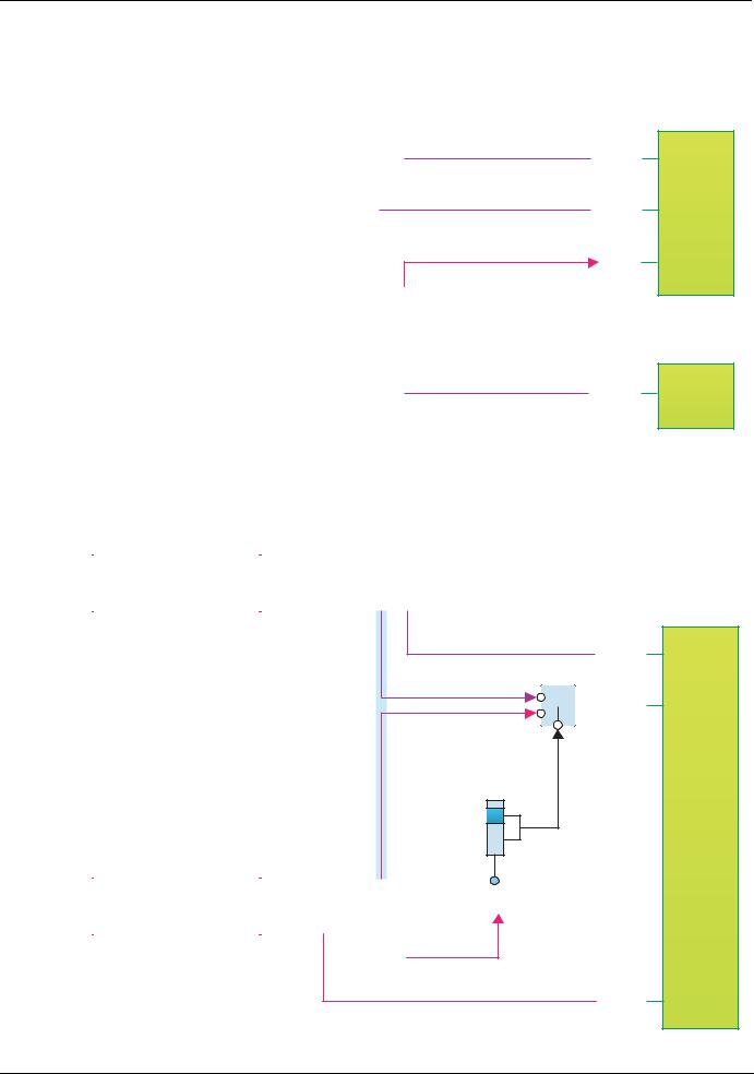
Fixed assignment to terminals, on CANopen and on "Controller Inside" card:
CANopen control word
bit 15 |
bit 14 |
bit 13 |
bit 12 |
|
bit 11 |
bit 10 |
bit 9 |
bit 8 |
|
bit 7 |
bit 6 |
bit 5 |
bit 4 |
|
bit 3 |
bit 2 |
bit 1 |
bit 0 |
||
|
|
|
|
|
|
|
|
|
|
|
|
|
|
|
|
|
|
|
|
|
|
|
|
|
|
|
|
|
|
|
|
|
|
|
|
|
|
|
|
|
|
|
|
|
|
|
|
|
|
|
|
|
|
|
|
|
|
|
|
|
|
|
Terminals
|
|
LI14 |
LI13 |
|
LI12 |
LI11 |
LI10 |
LI9 |
|
LI8 |
LI7 |
LI6 |
LI5 |
|
|
LI4 |
LI3 |
LI2 |
LI1 |
|
|
|
|
|
|
|
|
|
|
|
|
|
|
|
|
|
|
|
|
|
|
|
|
|
|
"Controller Inside" control word |
|
|
|
|
|
|||||||||||
|
|
|
|
|
|
|
|
|
||||||||||||
|
|
|
|
|
|
|
|
|
|
|
|
|
|
|
|
|
|
|
|
|
bit 15 |
bit 14 |
bit 13 |
bit 12 |
|
bit 11 |
bit 10 |
bit 9 |
bit 8 |
|
bit 7 |
bit 6 |
bit 5 |
bit 4 |
|
|
bit 3 |
bit 2 |
bit 1 |
bit 0 |
|
|
|
|
|
|
|
|
|
|
|
|
|
|
|
|
|
|
|
|
|
|
Function
 C201 A
 C202 B
LI2 C
Fast stop
 C401 Stop
Fixed assignment to terminals and on CANopen with command switching :
CANopen control word
bit 15 |
bit 14 |
bit 13 |
bit 12 |
|
bit 11 |
bit 10 |
bit 9 |
bit 8 |
|
bit 7 |
bit 6 |
bit 5 |
bit 4 |
|
bit 3 |
bit 2 |
bit 1 |
bit 0 |
|
|
|
|
|
|
|
|
|
|
|
|
|
|
|
|
|
|
|
Function
 C201 A


 Cd02 B
Command
switching
CCS
CANopen
Terminals
Terminals
LI14 |
LI13 |
|
LI12 |
LI11 |
LI10 |
LI9 |
|
LI8 |
LI7 |
LI6 |
LI5 |
|
LI4 |
LI3 |
LI2 |
LI1 |
|
|
|
|
|
|
|
|
|
|
|
|
|
|
|
|
|
|
|
|
|
|
|
|
|
|
|
|
|
|
|
|
|
|
|
|
|
LI2
 LI5 C
LI5 C
1755861 |
11/2009 |
15 |

I/O profile
Control word - run on state [2 wire] (2C)
Please refer to the [1.5 INPUTS / OUTPUTS CFG] (I-O-) section of the Programming Manual.
The forward run command is automatically assigned to input LI1 and to bit 0 of the various control words. This assignment cannot be modified.
The run command is active on state 1:
•Of input LI1, if the terminals are active
•Of bit 0 of the control word, if the network is active
Bits 1 to 15 of the control words can be assigned to drive functions.
bit 7 |
bit 6 |
bit 5 |
bit 4 |
|
|
|
|
Configurable |
Configurable |
Configurable |
Configurable |
|
|
|
|
|
|
|
|
bit 15 |
bit 14 |
bit 13 |
bit 12 |
|
|
|
|
Configurable |
Configurable |
Configurable |
Configurable |
|
|
|
|
bit 3 |
bit 2 |
bit 1 |
bit 0 |
|
|
|
|
Configurable |
Configurable |
Configurable |
Forward |
|
|
|
|
|
|
|
|
bit 11 |
bit 10 |
bit 9 |
bit 8 |
|
|
|
|
Configurable |
Configurable |
Configurable |
Configurable |
|
|
|
|
In the case of a [2 wire] (2C) run on state command and I/O profile, fixed assignment of a function input is possible using the following codes:
|
|
|
|
|
Fixed assignments |
|
|
|
||
Bit |
|
|
|
|
|
|
|
|
|
|
Drive terminals |
Logic I/O card |
Extended I/O |
|
Modbus |
|
CANopen |
Network card |
"ControllerInside" |
||
|
|
card |
|
|
card |
|||||
|
|
|
|
|
|
|
|
|
||
|
|
|
|
|
|
|
|
|
|
|
bit |
0 |
|
|
|
|
Forward |
|
|
|
|
|
|
|
|
|
|
|
|
|
|
|
bit |
1 |
LI2 |
- |
- |
|
C101 |
|
C201 |
C301 |
C401 |
|
|
|
|
|
|
|
|
|
|
|
bit |
2 |
LI3 |
- |
- |
|
C102 |
|
C202 |
C302 |
C402 |
|
|
|
|
|
|
|
|
|
|
|
bit |
3 |
LI4 |
- |
- |
|
C103 |
|
C203 |
C303 |
C403 |
|
|
|
|
|
|
|
|
|
|
|
bit |
4 |
LI5 |
- |
- |
|
C104 |
|
C204 |
C304 |
C404 |
|
|
|
|
|
|
|
|
|
|
|
bit |
5 |
LI6 |
- |
- |
|
C105 |
|
C205 |
C305 |
C405 |
|
|
|
|
|
|
|
|
|
|
|
bit |
6 |
- |
LI7 |
- |
|
C106 |
|
C206 |
C306 |
C406 |
|
|
|
|
|
|
|
|
|
|
|
bit |
7 |
- |
LI8 |
- |
|
C107 |
|
C207 |
C307 |
C407 |
|
|
|
|
|
|
|
|
|
|
|
bit |
8 |
- |
LI9 |
- |
|
C108 |
|
C208 |
C308 |
C408 |
|
|
|
|
|
|
|
|
|
|
|
bit |
9 |
- |
LI10 |
- |
|
C109 |
|
C209 |
C309 |
C409 |
|
|
|
|
|
|
|
|
|
|
|
bit 10 |
- |
- |
LI11 |
|
C110 |
|
C210 |
C310 |
C410 |
|
|
|
|
|
|
|
|
|
|
|
|
bit 11 |
- |
- |
LI12 |
|
C111 |
|
C211 |
C311 |
C411 |
|
|
|
|
|
|
|
|
|
|
|
|
bit 12 |
- |
- |
LI13 |
|
C112 |
|
C212 |
C312 |
C412 |
|
|
|
|
|
|
|
|
|
|
|
|
bit 13 |
- |
- |
LI14 |
|
C113 |
|
C213 |
C313 |
C413 |
|
|
|
|
|
|
|
|
|
|
|
|
bit 14 |
- |
- |
- |
|
C114 |
|
C214 |
C314 |
C414 |
|
|
|
|
|
|
|
|
|
|
|
|
bit 15 |
- |
- |
- |
|
C115 |
|
C215 |
C315 |
C415 |
|
|
|
|
|
|
|
|
|
|
|
|
For example, to assign the operating direction command to bit 1 of CANopen, simply configure the [Reverse assign.] (rrS) parameter with the value [C201] (C201).
16 |
1755861 |
11/2009 |

I/O profile
Control word - run on edge [3 wire] (3C)
Please refer to the [1.5 INPUTS / OUTPUTS CFG] (I-O-) section of the Programming Manual.
The stop command is automatically assigned to input LI1 and to bit 0 of the control words.
This assignment cannot be modified.
This command enables running on state 1:
•Of input LI1, if the terminals are active
•Of bit 0 of the control word, if the network is active
The forward run command is automatically assigned to input LI2 and to bit 1 of the control words.
This assignment cannot be modified.
The forward run command is active if the stop command is at 1 and on a rising edge (0 V 1):
•Of input LI2, if the terminals are active
•Of bit 1 of the control word, if the network is active
Bits 2 to 15 of the control words can be assigned to drive functions.
bit 7 |
bit 6 |
bit 5 |
bit 4 |
|
bit 3 |
bit 2 |
bit 1 |
bit 0 |
|
|
|
|
|
|
|
|
|
Configurable |
Configurable |
Configurable |
Configurable |
|
Configurable |
Configurable |
Forward |
Stop |
|
|
|
|
|
|
|
|
|
|
|
|
|
|
|
|
|
|
bit 15 |
bit 14 |
bit 13 |
bit 12 |
|
bit 11 |
bit 10 |
bit 9 |
bit 8 |
|
|
|
|
|
|
|
|
|
Configurable |
Configurable |
Configurable |
Configurable |
|
Configurable |
Configurable |
Configurable |
Configurable |
|
|
|
|
|
|
|
|
|
In the case of a [3 wire] (3C) run on state command and I/O profile, fixed assignment of a function input is possible using the following codes:
|
|
|
|
|
Fixed assignments |
|
|
|
||
Bit |
|
|
|
|
|
|
|
|
|
|
Drive terminals |
Logic I/O card |
Extended |
|
Modbus |
|
CANopen |
Network card |
"ControllerInside" |
||
|
|
I/O card |
|
|
card |
|||||
|
|
|
|
|
|
|
|
|
||
|
|
|
|
|
|
|
|
|
|
|
bit |
0 |
|
|
|
Authorization to run (Stop) |
|
|
|
||
|
|
|
|
|
|
|
|
|
|
|
bit |
1 |
|
|
|
|
Forward |
|
|
|
|
|
|
|
|
|
|
|
|
|
|
|
bit |
2 |
LI3 |
- |
- |
|
C102 |
|
C202 |
C302 |
C402 |
|
|
|
|
|
|
|
|
|
|
|
bit |
3 |
LI4 |
- |
- |
|
C103 |
|
C203 |
C303 |
C403 |
|
|
|
|
|
|
|
|
|
|
|
bit |
4 |
LI5 |
- |
- |
|
C104 |
|
C204 |
C304 |
C404 |
|
|
|
|
|
|
|
|
|
|
|
bit |
5 |
LI6 |
- |
- |
|
C105 |
|
C205 |
C305 |
C405 |
|
|
|
|
|
|
|
|
|
|
|
bit |
6 |
- |
LI7 |
- |
|
C106 |
|
C206 |
C306 |
C406 |
|
|
|
|
|
|
|
|
|
|
|
bit |
7 |
- |
LI8 |
- |
|
C107 |
|
C207 |
C307 |
C407 |
|
|
|
|
|
|
|
|
|
|
|
bit |
8 |
- |
LI9 |
- |
|
C108 |
|
C208 |
C308 |
C408 |
|
|
|
|
|
|
|
|
|
|
|
bit |
9 |
- |
LI10 |
- |
|
C109 |
|
C209 |
C309 |
C409 |
|
|
|
|
|
|
|
|
|
|
|
bit 10 |
- |
- |
LI11 |
|
C110 |
|
C210 |
C310 |
C410 |
|
|
|
|
|
|
|
|
|
|
|
|
bit 11 |
- |
- |
LI12 |
|
C111 |
|
C211 |
C311 |
C411 |
|
|
|
|
|
|
|
|
|
|
|
|
bit 12 |
- |
- |
LI13 |
|
C112 |
|
C212 |
C312 |
C412 |
|
|
|
|
|
|
|
|
|
|
|
|
bit 13 |
- |
- |
LI14 |
|
C113 |
|
C213 |
C313 |
C413 |
|
|
|
|
|
|
|
|
|
|
|
|
bit 14 |
- |
- |
- |
|
C114 |
|
C214 |
C314 |
C414 |
|
|
|
|
|
|
|
|
|
|
|
|
bit 15 |
- |
- |
- |
|
C115 |
|
C215 |
C315 |
C415 |
|
|
|
|
|
|
|
|
|
|
|
|
For example, to assign the operating direction command to bit 2 of CANopen, simply configure the [Reverse assign.] (rrS) parameter with the value [C202] (C202).
1755861 |
11/2009 |
17 |

I/O profile
Status word (ETA)
bit 7 |
bit 6 |
bit 5 |
bit 4 |
|
|
|
|
|
|
|
Reserved |
|
Power section |
|
Alarm |
Reserved (=1) |
line supply |
||
(= 0 or 1) |
||||
|
|
present |
||
|
|
|
||
|
|
|
|
bit 3 |
bit 2 |
bit 1 |
bit 0 |
|
|
|
|
|
|
Fault |
Running |
Ready |
Reserved |
|
(= 0 or 1) |
||||
|
|
|
||
|
|
|
|
bit 15 |
bit 14 |
bit 13 |
bit 12 |
|
bit 11 |
bit 10 |
bit 9 |
bit 8 |
|
|
|
|
|
|
|
|
|
Direction of |
Stop via STOP |
|
|
|
Reference |
Reference |
Command or |
|
Reserved (=0) |
Reserved (=0) |
|
reference via |
Reserved (=0) |
||||
rotation |
key |
|
outside limits |
reached |
||||
|
|
|
network |
|
||||
|
|
|
|
|
|
|
|
|
|
|
|
|
|
|
|
|
|
The status word is identical in the I/O profile and the CiA402 profile. For more information, see section “CiA402 profile”, page 21.
18 |
1755861 |
11/2009 |
I/O profile
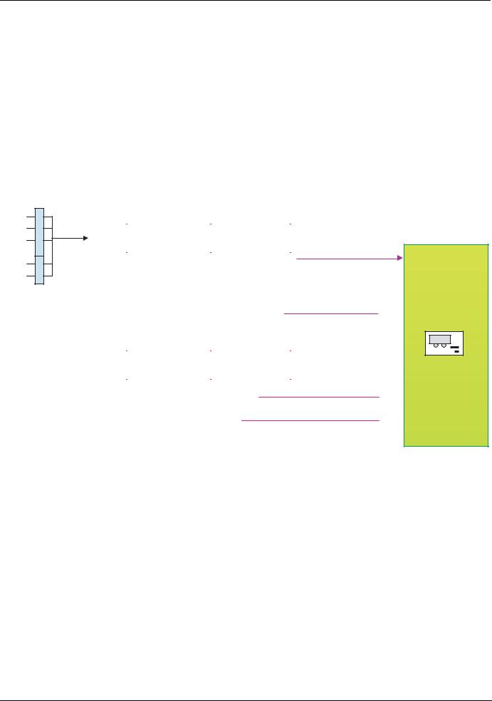
Example: I/O profile with positioning by sensors function
Please refer to the [1.7 APPLICATION FUNCT.] (FUn-) section of the Programming Manual, under "Positioning by sensors".
In this example, a PLC is used to control the transfer of parts on a conveyor composed of transfer tables. Each table is controlled by a variable speed drive. The PLC and the drives are connected via a CANopen network.
The PLC controls the operation of the installation via the CANopen bus.
The drive uses the stop sensor to inhibit transfer of the part if the next table is unavailable. In this case, the PLC enables the sensors. If the next table is free, the drive transfers the part without stopping. In this case, the PLC disables the sensors.
The stop sensor is directly connected to the drive terminals.
The slowdown sensor, which is also directly connected (to the drive) enables a more precise stop.
Configuration schematic diagram:
Command channel 1
Cd1
tEr
LCC
Mdb
CAn 
 nEt
nEt
APP
CANopen control word
bit 15 |
bit 14 |
bit 13 |
bit 12 |
|
bit 11 |
bit 10 |
bit 9 |
bit 8 |
|
bit 7 |
bit 6 |
bit 5 |
bit 4 |
|
bit 3 |
bit 2 |
bit 1 |
bit 0 |
||
|
|
|
|
|
|
|
|
|
|
|
|
|
|
|
|
|
|
|
|
|
|
|
|
|
|
|
|
|
|
|
|
|
|
|
|
|
|
|
|
|
|
|
|
|
|
|
|
|
|
|
|
|
|
|
|
|
|
|
|
|
|
|
Terminals
LI14 |
LI13 |
|
LI12 |
LI11 |
LI10 |
LI9 |
|
LI8 |
LI7 |
LI6 |
LI5 |
|
LI4 |
LI3 |
LI2 |
LI1 |
||
|
|
|
|
|
|
|
|
|
|
|
|
|
|
|
|
|
|
|
|
|
|
|
|
|
|
|
|
|
|
|
|
|
|
|
|
|
|
|
|
|
|
|
|
|
|
|
|
|
|
|
|
|
|
|
|
|
 C201
C201
 LI4
LI4
LI6
 LI5
LI5
LI8
Positioning
by sensors
Forward
Reverse
Disabling of sensors
Forward stop sensor Reverse stop sensor Forward slowdown sensor Reverse slowdown sensor
1755861 |
11/2009 |
19 |

I/O profile
Configure the following parameters:
Parameter |
Value |
Comment |
|
|
|
|
|
Type of command |
On state (2 wire) |
The run command is obtained via bit 0 of the CANopen control |
|
|
|
word. |
|
Profile |
I/O profile |
||
|
|||
|
|
|
|
Reference 1 configuration |
CANopen |
The reference comes from the CANopen card. |
|
|
|
|
|
Command 1 configuration |
CANopen |
The command comes from the CANopen card. |
|
|
|
|
|
Assignment of stop sensor |
Input LI4 |
|
|
|
|
|
|
Assignment of slowdown sensor |
Input LI5 |
|
|
|
|
|
|
Assignment of sensor disable command |
Bit 1 of CANopen control |
|
|
|
word |
|
|
|
|
|
Configuration via the remote graphic display terminal:
Menu |
Parameter |
Value |
|
|
|
|
|
[1.5 INPUTS / OUTPUTS CFG] (I-O-) |
[2/3 wire control] (tCC) |
[2 wire] (2C) |
|
|
|
|
|
[1.6 - COMMAND] (CtL-) |
[Profile] (CHCF) |
[I/O profile] (IO) |
|
|
|
|
|
|
[Ref. 1 channel] (Fr1) |
[CANopen] (CAn) |
|
|
|
|
|
|
[Cmd channel 1] (Cd1) |
[CANopen] (CAn) |
|
|
|
|
|
[1.7 APPLICATION FUNCT.] (FUn-) |
[Stop FW limit sw.] (SAF) |
[LI4] (LI4) |
|
[POSITIONING BY SENSORS] (LPO-) |
|
|
|
[Slowdown forward] (dAF) |
[LI5] (LI5) |
||
|
|||
|
|
|
|
|
[Disable limit sw.] (CLS) |
[C201] (C201) |
|
|
|
|
Note: On a [2 wire] (2C) state command, the forward command is automatically assigned to bit 0 of the CANopen control word.
20 |
1755861 |
11/2009 |
CiA402 profile
Functional description
bDrive operation involves two main functions, which are illustrated in the two diagrams below (the values in brackets are the CANopen addresses of the parameters):
•Control diagram:
Controlword |
Statemachine |
|
||||||||||||||
|
|
|
|
|
|
|
|
|
|
|
|
|
Statusword |
|||
(6040) |
|
|
|
|
|
|
|
|
|
|
|
|
|
|
|
(6041) |
|
|
|
|
|
|
|
|
|
|
|
|
|
|
|
|
|
|
|
|
|
|
|
|
|
|
|
|
|
|
|
|
|
|
|
|
|
|
|
|
|
|
|
|
|
|
|
|
|
|
|
• Simplified diagram of speed control in "Velocity" mode:
|
|
|
|
|
|
|
|
|
|
|
|
|
|
|
|
|
Power device |
|
|
||
vl_target_velocity |
|
|
Limit |
|
|
Ramp |
|
vl_velocity_demand |
|
|
|||||||||||
|
|
|
|
|
|
|
|
|
|
|
|
||||||||||
|
|
|
|
|
|
|
|
|
|
|
|
|
|
|
|
|
|
|
|
||
(6042) |
|
|
|
|
|
|
|
|
|
|
|
|
|
(6043) |
|
|
|
3 |
|
|
M |
|
|
|
|
|
|
|
|
|
|
|
|
|
|
|
|
|
|
|
|
|
|
|
|
|
|
|
|
|
|
|
|
|
|
|
|
|
|
|
|
|
|
|
|
|
|
|
vl_velocity_min_max amount (6046) |
|
|
vl_velocity_acceleration (6048) |
|
|
|
|
|
|
|
|
|
||||||
|
|
|
|
|
|
|
|
|
|
vl_velocity_acceleration (6049) |
|
|
|
|
|
|
|
|
|
||
|
|
|
|
|
|
|
|
|
|
|
|
|
|
|
|
|
|
|
|
|
|
|
|
|
|
|
|
|
|
|
|
|
|
|
|
|
|
|
|
|
|
|
|
|
|
|
|
|
|
|
|
|
|
|
|
|
|
|
|
|
|
|
|
|
|
|
|
|
|
|
|
|
|
|
|
|
|
|
|
|
|
|
|
vl_control_effort |
|
||
|
|
|
|
|
|
|
|
|
|
|
|
|
|
|
(6044) |
|
|
||||
bThe main parameters are shown with their CiA402 name and their CiA402/Drivecom index (the values in brackets are the parameter codes).
These diagrams translate as follows for the Altivar system:
• Control diagram:
Control word |
State machine |
|
|||||||||||||||
|
|
|
|
|
|
|
|
|
|
|
|
|
|
Status word |
|||
(CMD) |
|
|
|
|
|
|
|
|
|
|
|
|
|
|
|
|
(ETA) |
|
|
|
|
|
|
|
|
|
|
|
|
|
|
|
|
|
|
|
|
|
|
|
|
|
|
|
|
|
|
|
|
|
|
|
|
• Simplified diagram of speed regulation in "Velocity" mode:
Speed reference |
Reference limit |
|
|
Ramp |
|
||||||||
|
|
|
|
|
|
|
|
|
|
|
|||
(LFRD) |
|
|
|
|
|
|
|
|
|
|
|
|
|
|
|
|
|
|
|
|
|
|
|
|
|
||
|
|
|
|
|
|
|
|
|
|
|
|
|
|
|
|
|
|
|
|
|
|
|
|
|
|
|
|
|
|
|
|
|
|
|
|
|
|
Acceleration delta speed (SPAL) |
|
||
|
|
|
Velocity min amount (SMIL) |
|
|
Acceleration delta time (SPAT) |
|
||||||
|
|
|
Velocity max amount (SMAL) |
|
|
Deceleration delta speed (SPDL) |
|
||||||
|
|
|
|
|
|
|
|
|
|
Deceleration delta time (SPDT) |
|
||
|
|
|
|
|
|
|
|
|
|
|
|
|
|
Speed reference |
|
|
Power |
|
|
|
|
|
module |
|
|
||
after ramp |
|
|
|
3 |
|
|
(FRHD) |
|
|
|
|
M |
|
|
|
|
|
|
|
|
|
|
|
|
|
|
|
|
|
|
|
|
|
|
|
|
|
|
|
|
|
|
|
|
|
|
|
|
Output speed (RFRD)
1755861 |
11/2009 |
21 |

CiA402 profile
CiA402 state chart
Power section line supply present or absent |
Fault |
|||||||
|
|
|
|
|
|
|
|
|
|
Entry into |
|
From all states |
|||||
|
state chart |
|
|
|||||
|
|
|
|
|
|
|||
|
|
|
|
|
|
|
|
|
|
|
|
|
|
|
|
|
Fault |
|
|
|
|
|
|
|
|
|
|
|
|
|
|
|
|
|
|
|
|
|
|
|
|
|
|
|
|
Not ready to switch on |
Fault reaction active |
||||||
Fault disappeared and faults reset CMD=16#0080
Switch on disabled |
Fault |
or |
|
|
Disable voltage |
|
|
|
|
|
|
|
Disable |
|
|
|
|
||||
|
CMD=16#0000 |
|
|
|
|
|
|
|
voltage |
|
Disable |
|
|
||||
|
or |
|
|
|
|
|
|
|
CMD=16#0000 |
|
|
|
|||||
|
|
|
|
|
|
|
|
|
voltage |
|
|
||||||
|
STOP key |
|
|
|
Shutdown |
|
or |
|
|
|
|||||||
|
or |
|
CMD=16#0006 |
|
Quick stop |
|
CMD=16#0000 |
If Quick stop option code |
|||||||||
|
freewheel stop at |
|
|
|
|
|
|
|
CMD=16#0002 |
|
or |
= 2: |
|||||
|
the terminals |
|
|
|
|
|
|
|
or |
|
Quick stop |
transition after stop. |
|||||
|
or |
|
|
|
|
|
|
|
STOP key |
|
CMD=16#0002 |
If Quick stop option code |
|||||
|
Power Removal |
|
|
|
|
|
|
|
|
|
|
|
|
or |
= 6: |
||
|
|
|
|
|
|
|
|
|
|
|
|
|
|
|
STOP key |
|
Disable voltage |
|
|
|
|
|
|
|
|
|
|
|
|
|
|
|
or |
|
CMD=16#0000 |
|
|
|
|
|
|
|
Ready to switch on |
|
|
|
freewheel stop |
|
or |
||||
|
|
|
|
|
|
|
|
|
|
at the terminals |
|
||||||
|
|
|
|
|
|
|
|
|
|
|
|
|
|
|
|
STOP key |
|
|
|
|
|
|
|
|
|
|
|
|
|
|
|
|
or |
|
or |
|
|
|
|
|
|
|
|
|
|
|
|
|
|
|
modification |
|
freewheel stop at |
|
|
|
|
|
|
|
|
|
|
|
|
|
|
|
of a configuration |
|
terminals |
|
|
|
|
|
|
or |
|
|
|
|
|
|
|
parameter |
|
|
|
|
|
|
|
|
|
|
|
|
|
|
|
|
|
|
|||
|
|
|
|
|
|
|
|
|
|
|
|
|
|
|
|
||
|
|
|
|
|
|
|
|
|
|
|
|
|
|
|
|
|
|
|
|
|
|
|
|
|
|
|
|
|
|
|
|
|
|
|
|
|
|
|
|
|
|
Switch on |
|
Shutdown |
|
|
|
|
|||||
|
|
|
|
CMD=16#0007 |
|
CMD=16#0006 |
|
|
|
|
|||||||
|
|
|
|
|
|
|
|
|
|
|
|
|
|
|
|
|
|
|
|
|
|
|
|
|
|
|
|
|
|
|
|
|
|
||
|
|
Shutdown |
|
|
|
|
|
Switched on |
|
|
|
|
|
|
|||
|
|
|
|
|
|
|
|
|
|
|
|||||||
|
|
CMD=16#0006 |
|
|
|
|
|
|
|
|
|
|
|
|
|
|
|
|
|
|
|
|
|
|
|
|
|
|
|
|
|
|
|
|
|
|
|
|
|
|
|
|
|
|
|
|
|
|
|
|
|
|
|
|
|
|
|
|
|
|
|
|
|
|
|
|
|
|
|
|
|
|
|
|
|
|
|
|
|
|
|
|
|
|
|
|
|
|
|
|
|
|
|
|
|
|
|
|
|
Disable |
|
|
|
|
|
|
|
|
|
Switch on |
|
|
|
|
Enable |
|
operation |
|
|
|
|
||||
|
|
CMD=16#xxxF |
|
|
|
operation |
|
CMD=16#0007 |
|
|
|
|
|||||
|
|
|
|
CMD=16#xxxF |
|
or |
|
|
|
|
|||||||
|
|
|
|
|
|
|
|
|
|
fast stop |
|
|
|
|
|||
Operation enabled |
Quick stop |
Quick stop active |
|
CMD=16#0002 |
|||
|
|
Examples:
ETA=16#0637: Stop or forward, speed reached
ETA=16#8637: Stop or reverse, speed reached
ETA=16#0237: Forward, accelerating or decelerating
ETA=16#8237: Reverse, accelerating or decelerating
Power section line supply present
Key: |
State |
Value of |
|||||||
|
|
|
|
|
|
|
|
|
status word |
|
|
|
|
|
|
|
|
|
|
|
|
|
|
Switched on |
|
||||
|
|
|
|
|
|
|
|
|
|
|
|
|
|
|
|
|
|
|
|
|
|
|
|
|
|
|
|
|
|
|
|
|
|
|
|
|
|
|
|
|
|
|
|
Enable |
|
|
|
|
|
|
|
operation |
|
|
|
|
|
||
|
CMD=16#xxxF |
|
|
|
|
|
|||
|
|
|
|
||||||
Power |
absent |
Power |
present |
Power absent |
or present |
Transition condition |
Status display on |
with example of command |
graphic display terminal |
22 |
1755861 |
11/2009 |

CiA402 profile
Description of states
Each state represents an internal reaction by the drive.
This chart will change depending on whether the control word is sent (CMD) or an event occurs (a fault, for example). The drive state can be identified by the value of the status word (ETA).
1 - Not ready to switch on
Initialization starts. This is a transient state invisible to the communication network.
2 - Switch on disabled
The drive is inactive.
The drive is locked, no power is supplied to the motor.
For a separate control section, it is not necessary to supply AC power to the power section. For a separate control section with line contactor, the contactor is not controlled.
The configuration and adjustment parameters can be modified.
3 - Ready to switch on
Awaiting power section line supply.
For a separate control section, it is not necessary to supply AC power to the power section, but the system will expect it in order to change to state "4 - Switched on".
For a separate control section with line contactor, the contactor is not controlled.
The drive is locked, no power is supplied to the motor.
The configuration and adjustment parameters can be modified.
4 - Switched on
The drive is supplied with AC power but is stationary.
For a separate control section, the power section line supply must be present. For a separate control section with line contactor, the contactor is controlled.
The drive is locked, no power is supplied to the motor.
The power stage of the drive is ready to operate, but voltage has not yet been applied to the output.
The adjustment parameters can be modified.
Modification of a configuration parameter returns the drive to state "2 - Switch on disabled".
5 - Operation enabled
The drive is running.
For a separate control section, the power section line supply must be present. For a separate control section with line contactor, the contactor is controlled.
The drive is unlocked, power is supplied to the motor.
The drive functions are activated and voltage is applied to the motor terminals.
However, in the case of an open-loop drive, if the reference is zero or the "Halt" command is applied, no power is supplied to the motor and no torque is applied.
Auto-tuning (tUn) requires an injection of current into the motor. The drive must therefore be in state "5 - Operation enabled" for this command.
The adjustment parameters can be modified.
The configuration parameters cannot be modified.
Note: The command "4 - Enable operation" must be taken into consideration only if the channel is valid (see Communication monitoring page 56). In particular, if the channel is involved in the command and the reference, transition 4 will take place only after the reference has been received for the first time.
The reaction of the drive to a "Disable operation" command depends on the value of the "Disable operation option code" (DOTD) parameter:
•If the "Disable operation option code" parameter has the value 0, the drive changes to "4 - Switched on" and stops in freewheel stop.
•If the "Disable operation option code" parameter has the value 1, the drive stops on ramp and then changes to "4 - Switched on".
1755861 |
11/2009 |
23 |

CiA402 profile
6 - Quick stop active
Emergency stop
The drive performs a fast stop, after which restarting will only be possible once the drive has changed to the "Switch on disabled" state. During fast stop, the drive is unlocked and power is supplied to the motor.
The configuration parameters cannot be modified.
The condition for transition 12 to state "2 - Switch on disabled" depends on the value of the parameter "Quick stop option code" (QSTD):
•If the "Quick stop option code" parameter has the value 2, the drive stops according to the fast stop ramp and then changes to state "2 - Switch on disabled".
•If the "Quick stop option code" parameter has the value 6, the drive stops according to the fast stop ramp and then remains in state "6 - Quick stop active" until:
-A "Disable voltage" command is received
-Or the STOP key is pressed
-Or there is a freewheel stop command via the terminals
7 - Fault reaction active
Transient state during which the drive performs an action appropriate to the type of fault.
The drive function is activated or deactivated according to the type of reaction configured in the fault management parameters.
8 - Fault
Drive faulty.
The drive is locked, no power is supplied to the motor.
Summary
State |
Power section line supply for |
Power supplied to motor |
Modification of configuration |
|
separate control section |
parameters |
|||
|
|
|||
|
|
|
|
|
1 - Not ready to switch on |
Not required |
No |
Yes |
|
|
|
|
|
|
2 - Switch on disabled |
Not required |
No |
Yes |
|
|
|
|
|
|
3 - Ready to switch on |
Not required |
No |
Yes |
|
|
|
|
|
|
4 - Switched on |
Required |
No |
Yes, return to "2 - Switch on |
|
disabled" state |
||||
|
|
|
||
|
|
|
|
|
|
|
Yes, apart from an open-loop |
|
|
5 - Operation enabled |
Required |
drive with a zero reference or in |
No |
|
the event of a "Halt" command |
||||
|
|
|
||
|
|
for an open-loop drive. |
|
|
|
|
|
|
|
6 - Quick stop active |
Required |
Yes, during fast stop |
No |
|
|
|
|
|
|
7 - Fault reaction active |
Depends on fault management |
Depends on fault management |
- |
|
configuration |
configuration |
|||
|
|
|||
|
|
|
|
|
8 - Fault |
Not required |
No |
Yes |
|
|
|
|
|
24 |
1755861 |
11/2009 |

CiA402 profile
Control word (CMD)
bit 7 |
bit 6 |
bit 5 |
bit 4 |
|
|
|
|
|
|
Fault reset |
|
|
|
|
|
Reserved (=0) |
Reserved (=0) |
Reserved (=0) |
|
Ack. fault |
||||
|
|
|
||
|
|
|
|
|
|
|
|
|
|
bit 15 |
bit 14 |
bit 13 |
bit 12 |
|
|
|
|
|
|
Assignable |
Assignable |
Assignable |
Assignable |
|
|
|
|
|
bit 3 |
bit 2 |
bit 1 |
bit 0 |
|
|
|
|
|
|
Enable operation |
Quick stop |
Enable voltage |
Switch on |
|
|
||||
|
|
|
|
|
|
Emergency |
Authorization |
Contactor |
|
Run command |
to supply AC |
|||
stop |
control |
|||
|
power |
|||
|
|
|
||
|
|
|
|
bit 11 |
bit 10 |
bit 9 |
bit 8 |
|
|
|
|
|
|
By default, |
|
|
Halt |
|
direction of |
|
|
||
Reserved (=0) |
Reserved (=0) |
|
||
rotation |
Halt |
|||
|
|
|||
command. |
|
|
||
|
|
|
||
|
|
|
|
|
Transition |
|
bit 7 |
bit 3 |
bit 2 |
bit 1 |
bit 0 |
|
||
Command |
Final state |
|
|
|
|
|
|
Example value |
||
Fault |
Enable |
Quick |
Enable |
|
||||||
address |
Switch on |
|||||||||
|
|
|
||||||||
|
|
|
reset |
operation |
stop |
voltage |
|
|
||
Shutdown |
2, 6, 8 |
3 - Ready to |
|
x |
x |
1 |
1 |
0 |
16#0006 |
|
switch on |
|
|||||||||
|
|
|
|
|
|
|
|
|
||
|
|
|
|
|
|
|
|
|
|
|
Switch on |
3 |
4 - Switched on |
|
x |
x |
1 |
1 |
1 |
16#0007 |
|
|
|
|
|
|
|
|
|
|
|
|
Enable |
4 |
5 - Operation |
|
x |
1 |
1 |
1 |
1 |
16#000F |
|
operation |
enabled |
|
||||||||
|
|
|
|
|
|
|
|
|||
|
|
|
|
|
|
|
|
|
|
|
Disable |
5 |
4 - Switched on |
|
x |
0 |
1 |
1 |
1 |
16#0007 |
|
operation |
|
|||||||||
|
|
|
|
|
|
|
|
|
||
|
|
|
|
|
|
|
|
|
|
|
Disable voltage |
7, 9, 10, 12 |
2 - Switch on |
|
x |
x |
x |
0 |
x |
16#0000 |
|
disabled |
|
|||||||||
|
|
|
|
|
|
|
|
|
||
|
|
|
|
|
|
|
|
|
|
|
|
11 |
6 - Quick stop |
|
|
|
|
|
|
|
|
|
active |
|
|
|
|
|
|
|
||
Quick stop |
|
|
x |
x |
0 |
1 |
x |
16#0002 |
||
|
|
|
||||||||
7, 10 |
2 - Switch on |
|
||||||||
|
|
|
|
|
|
|
|
|||
|
disabled |
|
|
|
|
|
|
|
||
|
|
|
|
|
|
|
|
|
||
|
|
|
|
|
|
|
|
|
|
|
Fault reset |
15 |
2 - Switch on |
0 |
V 1 |
x |
x |
x |
x |
16#0080 |
|
disabled |
||||||||||
|
|
|
|
|
|
|
|
|
||
|
|
|
|
|
|
|
|
|
|
|
x: Value is of no significance for this command.
0 V 1: Command on rising edge.
1755861 |
11/2009 |
25 |

CiA402 profile
Stop commands:
The "Halt" command enables movement to be interrupted without having to leave the "5 - Operation enabled" state. The stop is performed in accordance with the [Type of stop] (Stt) parameter.
In the case of an open-loop drive, if the "Halt" command is active, no power is supplied to the motor and no torque is applied.
In the case of a closed-loop drive, if the "Halt" command is active, power continues to be supplied to the motor and torque is applied during stopping.
Regardless of the assignment of the [Type of stop] (Stt) parameter ([Fast stop] (FSt), [Ramp stop] (rMP), [Freewheel] (nSt), or [DC injection] (dCI)), the drive remains in the "5 - Operation enabled" state.
A Fast Stop command at the terminals or using a bit of the control word assigned to Fast Stop causes a change to the "4 - Switched on" state. A "Halt" command does not cause this transition.
A Freewheel Stop command at the terminals or using a bit of the control word assigned to Freewheel Stop causes a change to the "2 - Switch on disabled" state.
 WARNING
RISK OF EQUIPMENT DAMAGE
When the braking loop is configured, it is necessary to use the "Halt" command (bit 8 of CMD command word) to stop.
Failure to follow these instructions can result in death, serious injury or equipment damage.
Assigning control word bits
In the CiA402 profile, fixed assignment of a function input is possible using the following codes:
Bit |
Integrated Modbus |
CANopen |
Network card |
"Controller Inside" card |
|
|
|
|
|
bit 11 |
C111 |
C211 |
C311 |
C411 |
|
|
|
|
|
bit 12 |
C112 |
C212 |
C312 |
C412 |
|
|
|
|
|
bit 13 |
C113 |
C213 |
C313 |
C413 |
|
|
|
|
|
bit 14 |
C114 |
C214 |
C314 |
C414 |
|
|
|
|
|
bit 15 |
C115 |
C215 |
C315 |
C415 |
|
|
|
|
|
For example, to assign the DC injection braking to bit 13 of CANopen, simply configure the [DC injection assign.] (dCI) parameter with the [C213] (C213) value.
Bit 11 is assigned by default to the operating direction command [Reverse assign.] (rrS).
26 |
1755861 |
11/2009 |

CiA402 profile
Status word (ETA)
bit 7 |
bit 6 |
bit 5 |
bit 4 |
|
|
|
|
|
|
Warning |
Switch on |
Quick stop |
Voltage |
|
disabled |
enabled |
|||
|
|
|||
|
|
|
|
|
|
Power section |
Emergency |
Power section |
|
Alarm |
line supply |
line supply |
||
stop |
||||
|
disabled |
present |
||
|
|
|||
|
|
|
|
|
|
|
|
|
|
bit 15 |
bit 14 |
bit 13 |
bit 12 |
|
|
|
|
|
|
Direction of |
Stop via |
Reserved (=0) |
Reserved (=0) |
|
rotation |
STOP key |
|||
|
|
|||
|
|
|
|
bit 3 |
bit 2 |
bit 1 |
bit 0 |
|
|
|
|
|
|
Fault |
Operation |
Switched on |
Ready to |
|
enabled |
switch on |
|||
|
|
|||
|
|
|
|
|
|
|
|
Awaiting |
|
Fault |
Running |
Ready |
power section |
|
|
|
|
line supply |
|
|
|
|
|
bit 11 |
bit 10 |
bit 9 |
bit 8 |
|
|
|
|
Internal limit |
Target |
Remote |
|
active |
reached |
|
|
|
|
||
|
|
|
Reserved (=0) |
Reference |
Reference |
Command or |
|
reference via |
|
||
outside limits |
reached |
|
|
network |
|
||
|
|
|
|
|
|
|
|
|
|
bit 6 |
bit 5 |
bit 4 |
bit 3 |
bit 2 |
bit 1 |
bit 0 |
|
ETA |
|
|
Status |
Switch on |
Quick |
Voltage |
Fault |
Operation |
Switched |
Ready to |
|
masked by |
|
|
|
disabled |
stop |
enabled |
enabled |
on |
switch on |
|
16#006F (1) |
||
1 |
- Not ready to |
0 |
x |
x |
0 |
0 |
0 |
0 |
|
- |
|
|
switch on |
|
|||||||||
|
|
|
|
|
|
|
|
|
|
||
|
|
|
|
|
|
|
|
|
|
|
|
2 |
- Switch on |
1 |
x |
x |
0 |
0 |
0 |
0 |
|
16#0040 |
|
|
disabled |
|
|||||||||
|
|
|
|
|
|
|
|
|
|
||
|
|
|
|
|
|
|
|
|
|
|
|
3 |
- Ready to |
0 |
1 |
x |
0 |
0 |
0 |
1 |
|
16#0021 |
|
|
switch on |
|
|||||||||
|
|
|
|
|
|
|
|
|
|
||
|
|
|
|
|
|
|
|
|
|
|
|
4 |
- Switched on |
0 |
1 |
1 |
0 |
0 |
1 |
1 |
|
16#0023 |
|
|
|
|
|
|
|
|
|
|
|
|
|
5 |
- Operation |
0 |
1 |
1 |
0 |
1 |
1 |
1 |
|
16#0027 |
|
|
enabled |
|
|||||||||
|
|
|
|
|
|
|
|
|
|
||
|
|
|
|
|
|
|
|
|
|
|
|
6 |
- Quick stop |
0 |
0 |
1 |
0 |
1 |
1 |
1 |
|
16#0007 |
|
|
active |
|
|||||||||
|
|
|
|
|
|
|
|
|
|
||
|
|
|
|
|
|
|
|
|
|
||
7 - Fault reaction |
0 |
x |
x |
1 |
1 |
1 |
1 |
|
- |
||
|
active |
|
|||||||||
|
|
|
|
|
|
|
|
|
|
||
|
|
|
|
|
|
|
|
|
|
|
|
8 |
- Fault |
0 |
x |
x |
1 |
0 |
0 |
0 |
|
16#0008 (2) |
|
or |
16#0028 |
||||||||||
|
|
|
|
|
|
|
|
|
|||
|
|
|
|
|
|
|
|
|
|
|
|
x: In this state, the value of the bit can be 0 or 1.
(1)This mask can be used by the PLC program to test the chart state.
(2)Fault following state "6 - Quick stop active".
1755861 |
11/2009 |
27 |
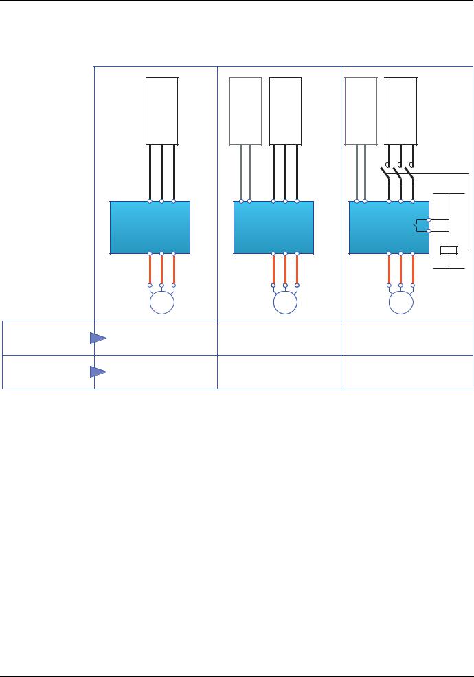
CiA402 profile
Starting sequence
The command sequence in the state chart depends on how power is being supplied to the drive.
There are three possible scenarios:
|
Power section line supply |
Control section |
power supply |
Power section line supply |
Control section |
power supply |
Power section line supply |
|
DRIVE |
|
|
DRIVE |
|
|
DRIVE |
|
M |
|
|
M |
|
|
M |
Power section |
|
|
|
|
|
|
Line contactor |
Direct |
|
|
Direct |
|
|
controlled by the drive |
|
line supply |
|
|
|
|
|||
|
|
|
|
|
|||
Control section |
Not separate (1) |
|
|
Separate |
|
|
Separate |
power supply |
|
|
|
|
(1) The power section supplies the control section.
28 |
1755861 |
11/2009 |
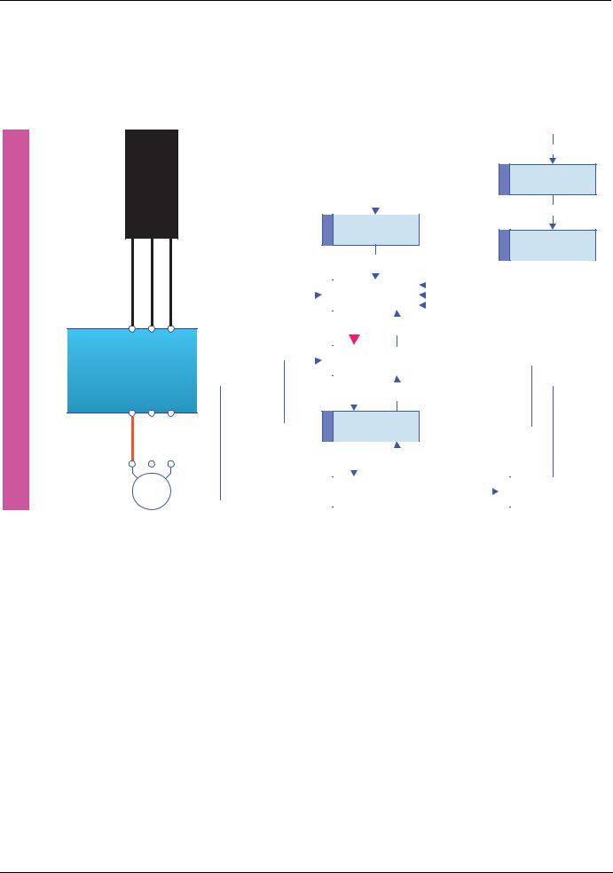
CiA402 profile
Sequence for a drive powered by the power section line supply
Both the power and control sections are powered by the power section line supply.
If power is supplied to the control section, it has to be supplied to the power section as well. The following sequence must be applied:
bStep 1
•Send the "2 - Shutdown" command
Powersection linesupply |
|
|
Not ready to |
||
|
Entry into state chart |
||||
|
|
|
0 |
|
|
|
|
|
|
|
|
|
|
|
|
|
|
|
1 |
switch on |
|||
From all states
13

Fault reaction
7active
14

8Fault
Bus or network
|
|
|
|
|
|
|
|
|
|
1 |
|
|
|
|
|
|
|
|
|
|
|
|
|
|
|
|
|
|
|
|
|
|
|
|
|
|
|
15 |
|
|
|
|
|||
|
|
|
|
|
|
|
|
|
|
|
|
|
|
|
|
|
|
|
|
|||
|
|
|
|
|
|
|
|
|
|
|
|
|
|
|
||||||||
|
|
|
|
|
|
2 |
Switch on |
|
|
|
|
|
|
|
|
|||||||
|
|
|
|
|
|
|
|
|
|
|
|
|
|
|
||||||||
|
|
|
|
|
|
disabled |
|
|
|
|
|
|
|
|
|
|
||||||
|
|
|
|
|
|
|
|
|
|
|
|
|
|
|
|
|
||||||
|
|
|
|
|
|
|
|
|
|
|
|
|
|
|
|
|
|
|
||||
|
|
|
Shutdown |
|
|
|
|
|
Disable voltage |
|
|
|
||||||||||
|
|
|
|
|
|
|
|
|
||||||||||||||
|
|
|
2 |
|
|
|
|
|
|
|||||||||||||
|
|
|
|
|
|
|
|
|
||||||||||||||
|
|
|
|
|
|
|
|
|
|
|
7 or Quick stop |
|
|
|
||||||||
|
|
|
|
|
|
|
|
|
|
|
|
|
|
|||||||||
|
|
|
|
|
|
|
Ready to |
|
|
|
Disable voltage |
|
|
|
||||||||
|
|
|
|
|
|
3 |
|
|
|
10 |
|
|||||||||||
DRIVE |
|
Disable |
|
|
|
switch on |
|
|
|
or Quick stop |
|
|||||||||||
|
9voltage |
|
|
|
|
|
|
|
|
|
|
|
|
|
|
|
12 |
|||||
|
|
Switch on 3 |
|
|
|
Shutdown |
||||||||||||||||
|
6 |
|
|
|
||||||||||||||||||
|
|
|
|
|
|
|
|
|
|
|
|
|
||||||||||
|
|
|
|
|
|
|
|
|
|
|
|
|
|
|
|
|
|
|
|
|
|
|
|
|
|
Shutdown 8 |
4 |
Switched on |
|
|
|
|
|
|
||||||||
|
|
|
|
|
|
|
|
|
|||||||||||
|
|
|
|
|
|
|
|
|
|
|
|
|
|
|
|
|
|
|
|
|
|
|
|
|
Enable |
|
|
|
|
Disable |
|
|
|
|
|||||
|
|
|
|
|
|
|
|
|
|
|
|
|
|||||||
|
|
|
|
|
4 |
|
|
|
|
|
|
||||||||
|
|
|
|
|
operation |
5 |
|
|
|
|
|||||||||
|
|
|
|
|
|
|
operation |
|
|
|
|
||||||||
|
|
|
|
|
|
|
|
|
|
|
|
|
|
|
|
||||
|
|
|
|
|
|
|
|
|
|
|
|
|
|
|
|
|
|
||
|
|
|
|
|
|
|
|
Operation |
|
|
|
|
|
|
Quick stop |
||||
M |
|
5 |
|
|
|
11 |
|
|
6 |
||||||||||
|
|
|
enabled |
|
|
|
|
|
|
|
active |
||||||||
|
|
|
|
|
|
|
|||||||||||||
|
|
|
|
|
|
|
|
|
|
|
|
Quick stop |
|
|
|
||||
|
|
|
|
|
|
|
|
|
|
|
|
|
|
|
|
|
|||
1755861 |
11/2009 |
29 |
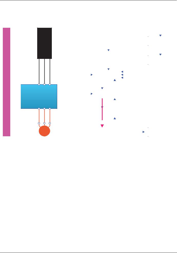
CiA402 profile
bStep 2
•Check that the drive is in the "3 - Ready to switch on" state.
•Then send the "4 - Enable operation" command.
•The motor can be controlled (send a reference not equal to zero).
From all states
Bus or network
Power section line supply
DRIVE
M
|
|
|
|
|
|
|
|
|
|
|
|
|
|
|
|
|
|
|
|
|
|
|
|
|
|
|
|
|
|
|
|
|
|
|
|
|
|
|
|
|
|
|
|
|
|
|
13 |
||
|
|
|
|
|
|
|
|
|
|
|
|
|
|
|
|
|
|
|
|
|
|
|
|
|
|
|
|
|
|
|
|
|
|
|
|
|
|
|
|
|
|
|
|
|
|
|
|
|
|
|
|
|
|
|
|
Entry into state chart |
|
7 |
Fault reaction |
|||||||||||||||
|
|
|
|
|
|
|
|
|
|
|
|
|
|
|
|
|
|
|
|
|
|
active |
||
|
|
|
|
|
|
|
|
|
|
|
|
|
|
|
|
|
|
|
|
|
|
|
||
|
|
|
|
|
|
|
|
|
|
0 |
|
|
|
|
|
|
|
|
|
|
|
|
|
|
|
|
|
|
|
|
|
|
|
|
|
|
|
|
|
|
|
|
|
|
|
|
14 |
||
|
|
|
|
|
|
|
|
|
|
|
|
|
|
|
|
|
|
|
|
|
|
|||
|
|
|
|
|
|
1 |
Not ready to |
|
|
|
|
|
|
|
|
|
|
|||||||
|
|
|
|
|
|
|
|
|
|
|
|
|
|
|
|
|||||||||
|
|
|
|
|
|
switch on |
|
|
|
|
|
|
8 |
|
|
Fault |
||||||||
|
|
|
|
|
|
|
|
|
|
|
|
|
|
|
|
|||||||||
|
|
|
|
|
|
|
|
|
|
|
|
|
|
|
|
|
|
|
|
|
|
|||
|
|
|
|
|
|
|
|
|
|
1 |
|
|
|
|
|
|
|
|
|
|
|
|
|
|
|
|
|
|
|
|
|
|
|
|
|
|
|
|
|
|
|
|
|
|
|
||||
|
|
|
|
|
|
|
|
|
|
|
|
|
|
|
|
|
|
|
|
|
|
|
|
|
|
|
|
|
|
|
|
|
|
|
|
|
|
|
|
|
|
|
|
|
15 |
|
|
|
|
|
|
|
|
|
|
2 |
|
Switch on |
|
|
|
|
|
|
|
|
|
|||||||
|
|
|
|
|
|
|
|
|
|
|
|
|
|
|
|
|
||||||||
|
|
|
|
|
|
|
|
|
|
|
|
|
|
|
|
|
|
|||||||
|
|
|
|
|
|
|
|
disabled |
|
|
|
|
|
|
|
|
|
|
|
|||||
|
|
|
|
|
|
|
|
|
|
|
|
|
|
|
|
|
|
|
|
|||||
|
|
|
|
|
|
|
|
|
|
|
|
|
|
|
|
|
|
|
|
|||||
|
|
|
|
|
|
|
|
|
|
|
|
|
|
|
|
|
|
|
|
|
|
|
||
|
|
|
|
|
|
|
|
|
|
|
|
|
|
|
|
|
|
|
|
|
|
|
|
|
|
|
|
|
Switch on 2 |
|
|
|
|
Disable voltage |
|
|
|
|
|
|
|||||||||
|
|
|
|
7 |
|
|
|
|
|
|
||||||||||||||
|
|
|
|
|
|
|
|
|
|
or Quick stop |
|
|
|
|
|
|
||||||||
|
|
|
|
|
|
|
|
|
|
|
|
|
|
|
|
|
|
|
|
|||||
|
|
|
|
|
|
|
|
|
|
|
|
|
|
|
|
|
|
|
|
|||||
|
|
|
|
|
|
3 |
|
|
Ready to |
|
|
|
Disable voltage |
|
|
|
||||||||
|
|
|
|
|
|
|
|
10 |
|
|||||||||||||||
|
|
Disable |
|
|
|
|
|
switch on |
|
|
|
or Quick stop |
|
|
|
|||||||||
9 |
|
|
|
|
|
|
|
|
|
|
|
|
|
|
|
|
|
|
|
|
12 |
|||
|
|
voltage |
|
|
|
|
|
|
|
|
|
|
|
|
|
|
|
|
|
|
|
|||
|
|
|
Switch on |
3 |
|
|
|
|
|
|
|
|
|
|
|
|
|
|
|
|||||
|
|
|
|
6 Shutdown |
|
|
|
|
|
|
||||||||||||||
|
|
|
|
|
|
|
|
|
|
|
|
|
|
|
|
|
|
|||||||
|
|
|
|
|
|
|
|
|
|
|
|
|
|
|
|
|
|
|
|
|
|
|||
|
|
|
|
|
|
|
|
|
|
|
|
|
|
|
|
|
|
|
|
|
|
|||
|
|
|
|
|
|
4 |
|
|
Switched on |
|
|
|
|
|
|
|
|
|
|
|||||
|
|
Shutdown8 |
|
|
|
|
|
|
|
|
|
|
|
|||||||||||
|
|
|
|
|
|
|
|
|
|
|
|
|||||||||||||
|
|
|
|
|
|
|
|
|
|
|
|
|
|
|
|
|
|
|
|
|
|
|
|
|
|
|
|
|
Enable |
|
4 |
|
|
|
|
Disable |
|
|
|
|
|
|
|||||||
|
|
|
|
|
|
|
|
|
|
|
|
|
|
|
||||||||||
|
|
|
|
5 |
|
|
|
|
|
|
||||||||||||||
|
|
|
|
operation |
|
|
operation |
|
|
|
|
|
|
|||||||||||
|
|
|
|
|
|
|
|
|
|
|
|
|||||||||||||
|
|
|
|
|
|
|
|
|
|
|
|
|
|
|
|
|||||||||
|
|
|
|
|
|
5 |
|
|
Operation |
|
|
|
11 |
|
|
6 |
|
Quick stop |
||||||
|
|
|
|
|
|
|
|
|
|
|
|
|
||||||||||||
|
|
|
|
|
|
|
|
|
enabled |
|
|
|
|
|
|
active |
||||||||
|
|
|
|
|
|
|
|
|
|
|
|
Quick stop |
|
|
|
|
||||||||
|
|
|
|
|
|
|
|
|
|
|
|
|
|
|
|
|
|
|
|
|
|
|||
Note: It is possible, but not necessary, to send the "3 - Switch on" command followed by the "4 - Enable Operation" command to switch successively into the states "3 - Ready to Switch on", "4 - Switched on" and then "5 - Operation Enabled".
The "4 - Enable operation" command is sufficient.
30 |
1755861 |
11/2009 |
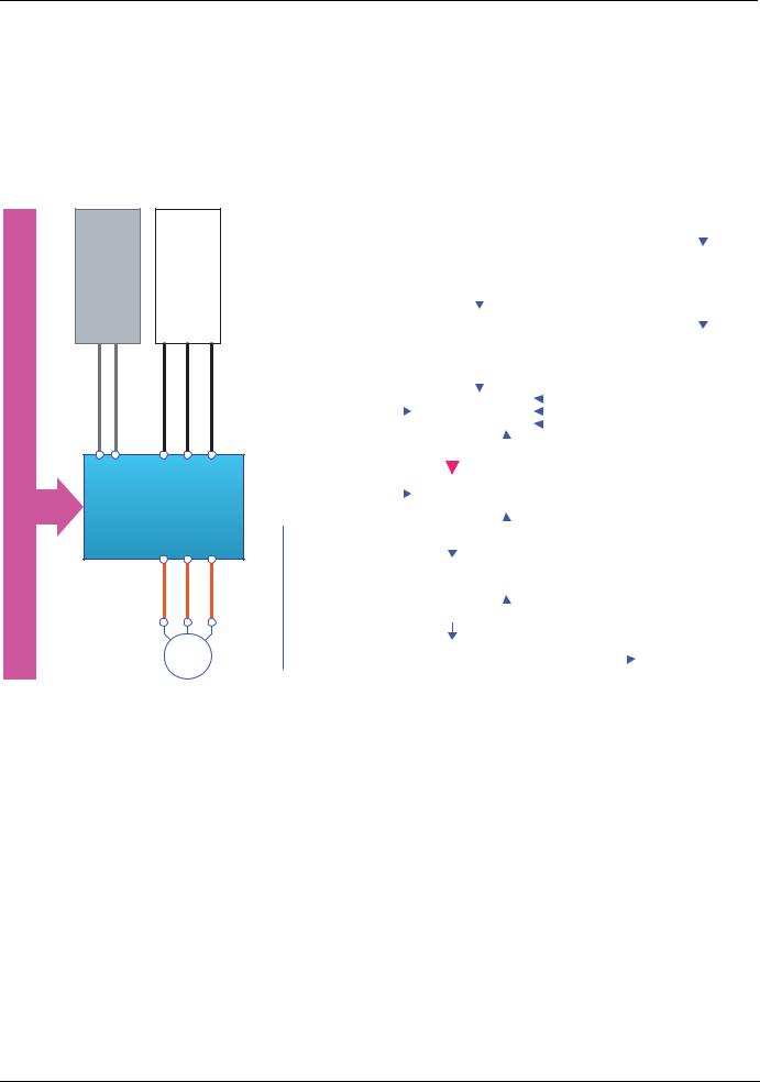
CiA402 profile
Sequence for a drive with separate control section
Power is supplied separately to the power and control sections.
If power is supplied to the control section, it does not have to be supplied to the power section as well. The following sequence must be applied:
bStep 1
•The power section line supply is not necessarily present.
•Send the "2 - Shutdown" command
From all states
Control section power supply |
Power section line supply |
Bus or network |
DRIVE |
M
|
|
|
|
|
|
|
|
|
|
|
|
|
|
|
|
|
|
|
|
|
|
|
|
|
|
|
|
|
|
|
|
|
|
|
|
|
|
|
|
|
|
|
|
|
|
|
|
|
13 |
||
|
|
|
|
|
|
|
|
|
|
|
|
|
|
|
|
|
|
|
|
|
|
|
|
|
|
|
|
|
|
|
|
|
|
|
|
|
|
|
|
|
|
|
|
|
|
|
|
|
|
|
|
|
|
|
|
|
Entry into state chart |
|
7 |
Fault reaction |
|||||||||||||||||
|
|
|
|
|
|
|
|
|
|
|
|
|
|
|
|
|
|
|
|
|
|
|
active |
||
|
|
|
|
|
|
|
|
|
|
|
|
|
|
|
|
|
|
|
|
|
|
|
|
||
|
|
|
|
|
|
|
|
|
|
0 |
|
|
|
|
|
|
|
|
|
|
|
|
|
|
|
|
|
|
|
|
|
|
|
|
|
|
|
|
|
|
|
|
|
|
|
|
|
|
14 |
||
|
|
|
|
|
|
|
|
|
|
|
|
|
|
|
|
|
|
|
|
|
|
|
|||
|
|
|
|
|
1 |
Not ready to |
|
|
|
|
|
|
|
|
|
|
|
||||||||
|
|
|
|
|
|
|
|
|
|
|
|
|
|
|
|
||||||||||
|
|
|
|
switch on |
|
|
|
|
|
|
|
|
|
|
|
|
|||||||||
|
|
|
|
|
|
|
|
|
|
8 |
|
|
Fault |
||||||||||||
|
|
|
|
|
|
|
|
|
|
|
|
|
|
|
|||||||||||
|
|
|
|
|
|
|
|
|
|
|
|
|
|
|
|
|
|
|
|
|
|
|
|||
|
|
|
|
|
|
|
|
|
|
1 |
|
|
|
|
|
|
|
|
|
|
|
|
|
|
|
|
|
|
|
|
|
|
|
|
|
|
|
|
|
|
|
|
|
|
|
|
|
||||
|
|
|
|
|
|
|
|
|
|
|
|
|
|
|
|
|
|
|
|
|
|
|
|
|
|
|
|
|
|
|
|
|
|
|
|
|
|
|
|
|
15 |
|
|
|
|
||||||
|
|
|
|
|
2 |
Switch on |
|
|
|
|
|
|
|
|
|
|
|
||||||||
|
|
|
|
|
|
|
|
|
|
|
|
|
|
|
|
||||||||||
|
|
|
|
|
|
|
disabled |
|
|
|
|
|
|
|
|
|
|
|
|
||||||
|
|
|
|
|
|
|
|
|
|
|
|
|
|
|
|
|
|
|
|
||||||
|
|
|
|
|
|
|
|
|
|
|
|
|
|
|
|
|
|
|
|
|
|
||||
|
|
Shutdown |
|
|
|
|
|
|
|
Disable voltage |
|
|
|
|
|
|
|||||||||
|
|
|
|
|
|
|
|
|
|
|
|
|
|
||||||||||||
|
|
2 |
|
|
|
|
|
|
|
|
|
|
|||||||||||||
7 |
|
|
|
|
|
|
|||||||||||||||||||
|
|
|
|
|
|
|
|
|
|
or Quick stop |
|
|
|
|
|
|
|||||||||
|
|
|
|
|
|
|
|
|
|
|
|
|
|
|
|
||||||||||
|
|
|
|
|
|
|
|
|
|
|
|
|
|
|
|
|
|
|
|||||||
|
|
|
|
|
|
|
|
|
|
|
|
|
|
|
|
|
|
|
|
||||||
|
|
|
|
|
3 |
|
Ready to |
|
|
|
|
Disable voltage |
|
|
|
||||||||||
|
|
|
|
|
|
|
|
|
10 |
|
|||||||||||||||
|
Disable |
|
|
|
switch on |
|
|
|
|
|
or Quick stop |
|
|||||||||||||
|
|
|
|
|
|
|
|
|
|
|
|||||||||||||||
9 voltage |
|
|
|
|
|
|
|
|
|
|
|
|
|
|
|
|
|
|
|
|
12 |
||||
|
Switch on 3 |
|
|
|
|
Shutdown |
|
|
|
|
|
|
|||||||||||||
6 |
|
|
|
|
|
|
|||||||||||||||||||
|
|
|
|
|
|
|
|
|
|
|
|
|
|
|
|
||||||||||
|
|
|
|
|
|
|
|
|
|
|
|
|
|
|
|
|
|
|
|
|
|
|
|
|
|
|
|
|
|
|
|
|
|
|
|
|
|
|
|
|
|
||||||||||
|
|
|
|
|
|
Switched on |
|
|
|
|
|
|
|
|
|||||||||||
|
Shutdown 8 |
|
4 |
|
|
|
|
|
|
||||||||||||||||
|
|
|
|
|
|
|
|
|
|||||||||||||||||
|
|
|
|
|
|
|
|
|
|
|
|
|
|
|
|
|
|
|
|
|
|
||||
|
|
|
Enable |
|
|
|
|
|
|
Disable |
|
|
|
|
|
|
|||||||||
|
|
|
|
|
|
|
|
|
|
|
|
|
|||||||||||||
|
|
|
|
|
|
|
|
|
|
|
|
|
|
||||||||||||
|
|
|
operation 4 |
5 |
|
|
|
|
|
|
|||||||||||||||
|
|
|
operation |
|
|
|
|
|
|
||||||||||||||||
|
|
|
|
|
|
|
|
|
|
|
|
||||||||||||||
|
|
|
|
|
|
|
|
|
|
|
|
|
|
|
|
|
|
|
|
||||||
|
|
|
|
|
|
|
|
|
|
|
|
|
|
|
|
|
|
|
|
||||||
|
|
|
|
|
5 |
Operation |
|
|
|
|
11 |
|
|
6 |
|
Quick stop |
|||||||||
|
|
|
|
|
|
|
|
|
|
|
|
||||||||||||||
|
|
|
|
|
|
|
enabled |
|
|
|
|
|
|
active |
|||||||||||
|
|
|
|
|
|
|
|
|
|
||||||||||||||||
|
|
|
|
|
|
|
|
|
|
|
|
Quick stop |
|
|
|
|
|||||||||
|
|
|
|
|
|
|
|
|
|
|
|
|
|
|
|
||||||||||
|
|
|
|
|
|
|
|
|
|
|
|
|
|
|
|
|
|
|
|
|
|
|
|
|
|
1755861 |
11/2009 |
31 |
Loading...