Schneider Electric HC-201 Installation Instructions

HC-201
Electric Duct Humidistat, Two-Position
General Instructions
APPLICATION
For low or line voltage on-off control of humidifiers, dehumidifiers, valves, solenoid valves, compressors, relay, etc.
SPECIFICATIONS
Control Dial Settings: 15 to 95% R.H. Humidity Sensing Element: Nylon ribbon Differential: 5% R.H.
Environment:
Ambient Temperature Limits,
Shipping & Storage, -40 to 140°F (-40 to 60°C). Operating, 40 to 125°F (4 to 52°C).
Humidity, 5 to 95% R.H., non-condensing. Location, NEMA 1, indoor location only.
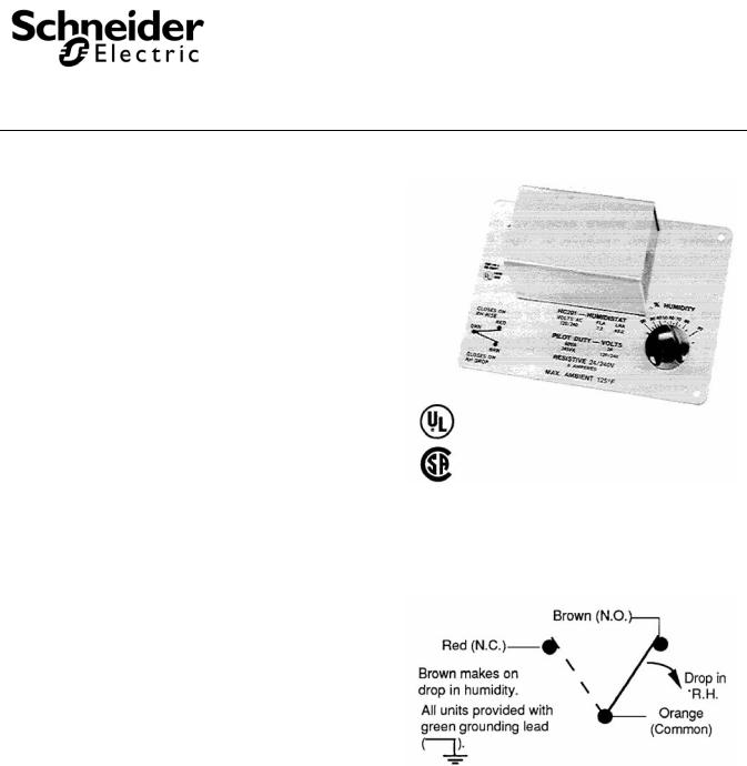
Electrical Switch: Snap-acting SPDT (See Figure 1). Ratings, See Table 1.
Connections: Coded screw terminal.
Cover: Metal.
Mounting: The outside surface of return air duct. Mounting template and five mounting screws provided.
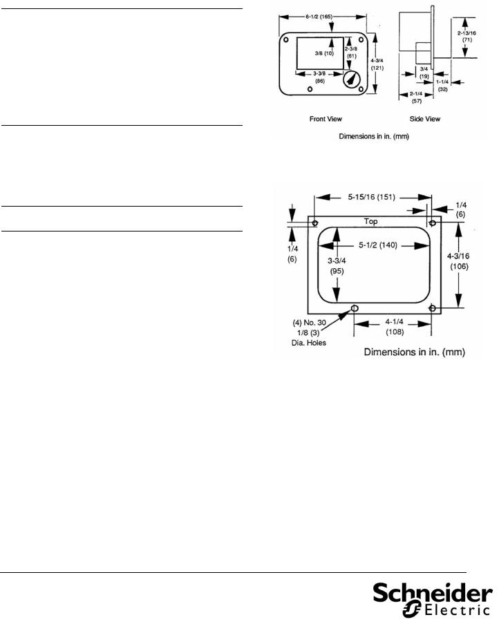
Dimensions: 4-3/4" x 6-1/2" x 3-1/2" (121 x 165 x 89). See Figure 2.
Table-1 Maximum Electrical Ratings.
AC Volt |
FLA |
LRA |
Resistive |
Pilot Duty |
|
50/60 Hz |
Amps |
VA |
|||
|
|
||||
24 |
- |
- |
8 |
60 |
|
120 |
7.2 |
43.2 |
8 |
345 |
|
240 |
3.6 |
21.6 |
8 |
345 |
PRE-INSTALLATION
Inspection
Inspect the carton for damage, if damaged notify the
appropriate carrier immediately. Inspect the device for Figure-1 Switch Action and Terminal Identification. obvious damage due to shipping. Return damaged products.
Required Installation Items
•Wiring Diagrams
•Tools (not provided):
DVM (digital volt-ohm meter)
Appropriate screwdriver for terminal connections and mounting screws
Appropriate drill bit for mounting screws
•(5) Mounting screws (provided)
•(1) Cover screw (provided)
Printed in U.S.A. 4/10 |
© Copyright 2010 Schneider Electric All Rights Reserved. |
F-24213-3 |

INSTALLATION
Caution:
•Installer must be a qualified, experienced technician
•Disconnect power before installation to prevent electrical shock and equipment damage.
•Make all connections in accordance with electrical wiring diagram and in accordance with national and local electrical codes. Use copper conductors only.
•NEMA Type 1 covers are intended for indoor use primarily to provide a degree of protection against contact with the enclosed components.
MOUNTING PROCEDURE
Mount the HC-201 on the outside surface of the return air duct in a horizontal position where it is exposed to freely circulating air (other mounting positions are possible but not preferred).
Caution: Avoid locations where excessive moisture, corrosive fumes, vibration or high ambient temperatures are present.
See Figure 3 for template dimensions for mounting.
1.Remove adhesive from the back of mounting template and press template to desired mounting location on duct.
2.Drill the four mounting holes as indicated on template, using No. 30, 1/8-inch (3 mm) diameter drill.
3.Cut out center portion of duct as outlined on template.
4.Using four (4) of the provided mounting screws, mount humidistat to the duct.
5.Remove the cover and make all electrical connections in accordance with job wiring diagram and in compliance with national and local electrical codes.
6.Replace the cover and install cover screw provided.
7.Turn dial knob to desired setting. If locked dial setting is desired, remove dial knob, tighten the dial lock screw and replace knob.
FIELD REPAIR
The HC-201 Humidistat is not field repairable.
Figure-1 HC-201 Dimensions.
Figure-2 Template Dimensions.
On October 1st, 2009, TAC became the Buildings business of its parent company Schneider Electric. This document reflects the visual identity of Schneider Elect however there remains references to TAC as a corporate brand in the body copy. As each document is updated, the body copy will be changed to reflect appropr corporate brand changes.
Copyright 2010, Schneider Electric
All brand names, trademarks and registered trademarks are the property of their respective owners. Information contained within this document is subject to change without notice.
F-24213-3
 Loading...