


Schneider Electric ACF402, ACF400 User Manual
Installation and
Operation
Rack Air Removal
Unit SX
ACF400, ACF402

This manual is available in English on the enclosed CD.
Dieses Handbuch ist in Deutsch auf der beiliegenden CD-ROM verfügbar.
Deze handleiding staat in het Nederlands op de bijgevoegde cd.
Este manual está disponible en español en el CD-ROM adjunto.
Ce manuel est disponible en français sur le CD-ROM ci-inclus.
Questo manuale è disponibile in italiano nel CD-ROM allegato.
本マニュアルの日本語版は同梱の CD-ROM からご覧になれます。
Instrukcja Obs
O manual em Português está disponível no CD-ROM em anexo.
Данное руководство на русском языке имеется на прилагаемом компакт-диске.
您可以从包含的 CD 上获得本手册的中文版本。
您可以从付属的CD上获得本手册的中文版本。
ługi w jezyku polskim jest dostepna na CD.
동봉된 CD 안에 한국어 매뉴얼이 있습니다 .

American Power Conversion Legal Disclaimer
The information presented in this manual is not warranted by the American Power Conversion Corporation to be authoritative, error free, or complete. This publication is not meant to be a substitute for a
detailed operational and site specific development plan. Therefore, American Power Conversion Corporation assumes no liability for damages, violations of codes, improper installation, system failures, or any
other problems that could arise based on the use of this Publication.
The information contained in this Publication is provided as is and has been prepared solely for the purpose of evaluating data center design and construction. This Publication has been compiled in good faith
by American Power Conversion Corporation. However, no representation is made or warranty given,
either express or implied, as to the completeness or accuracy of the information this Publication contains.
IN NO EVENT SHALL AMERICAN POWER CONVERSION CORPORATION, OR ANY PARENT, AFFILIATE OR SUBSIDIARY COMPANY OF AMERICAN POWER CONVERSION
CORPORATION OR THEIR RESPECTIVE OFFICERS, DIRECTORS, OR EMPLOYEES BE
LIABLE FOR ANY DIRECT, INDIRECT, CONSEQUENTIAL, PUNITIVE, SPECIAL, OR
INCIDENTAL DAMAGES (INCLUDING, WITHOUT LIMITATION, DAMAGES FOR LOSS
OF BUSINESS, CONTRACT, REVENUE, DATA, INFORMATION, OR BUSINESS INTERRUPTION) RESULTING FROM, ARISING OUT, OR IN CONNECTION WITH THE USE OF,
OR INABILITY TO USE THIS PUBLICATION OR THE CONTENT, EVEN IF AMERICAN
POWER CONVERSION CORPORATION HAS BEEN EXPRESSLY ADVISED OF THE POSSIBILITY OF SUCH DAMAGES. AMERICAN POWER CONVERSION CORPORATION
RESERVES THE RIGHT TO MAKE CHANGES OR UPDATES WITH RESPECT TO OR IN
THE CONTENT OF THE PUBLICATION OR THE FORMAT THEREOF AT ANY TIME
WITHOUT NOTICE.
Copyright, intellectual, and all other proprietary rights in the content (including but not limited to software, audio, video, text, and photographs) rests with American Power Conversion Corporation or its
licensors. All rights in the content not expressly granted herein are reserved. No rights of any kind are
licensed or assigned or shall otherwise pass to persons accessing this information.
This Publication shall not be for resale in whole or in part.


Contents
General Information ........................................................ 1
Overview . . . . . . . . . . . . . . . . . . . . . . . . . . . . . . . . . . . . . . . . . . . . . . . . 1
Product description . . . . . . . . . . . . . . . . . . . . . . . . . . . . . . . . . . . 1
Safety Information. . . . . . . . . . . . . . . . . . . . . . . . . . . . . . . . . . . . . . . . . 2
Inventory . . . . . . . . . . . . . . . . . . . . . . . . . . . . . . . . . . . . . . . . . . . . . . . . 3
Tools required (not provided) . . . . . . . . . . . . . . . . . . . . . . . . . . . . 3
Receiving inspection . . . . . . . . . . . . . . . . . . . . . . . . . . . . . . . . . . 3
Installation ....................................................................... 4
Attach the Mounting Frame . . . . . . . . . . . . . . . . . . . . . . . . . . . . . . . . . 4
Remove the doors . . . . . . . . . . . . . . . . . . . . . . . . . . . . . . . . . . . . . . . . 4
Secure the mounting frame to the enclosure . . . . . . . . . . . . . . . . 6
Extend and attach the mounting frame . . . . . . . . . . . . . . . . . . . . . 8
Install the fan assembly . . . . . . . . . . . . . . . . . . . . . . . . . . . . . . . 9
Install the anti-tip strap . . . . . . . . . . . . . . . . . . . . . . . . . . . . . . . 10
Connect the ground wire . . . . . . . . . . . . . . . . . . . . . . . . . . . . . . 10
Fan Assembly Extension . . . . . . . . . . . . . . . . . . . . . . . . . . . . . . . . . . 11
Adjust the fan assembly extension . . . . . . . . . . . . . . . . . . . . . . . 11
Attach the fan assembly extension . . . . . . . . . . . . . . . . . . . . . . . 12
Connect the Power Supply. . . . . . . . . . . . . . . . . . . . . . . . . . . . . . . . . 13
Optional Items . . . . . . . . . . . . . . . . . . . . . . . . . . . . . . . . . . . . . . . . . . . 14
Operation ....................................................................... 15
Display Interface . . . . . . . . . . . . . . . . . . . . . . . . . . . . . . . . . . . . . . . . . 15
Navigating the interface . . . . . . . . . . . . . . . . . . . . . . . . . . . . . . . 16
Password entry . . . . . . . . . . . . . . . . . . . . . . . . . . . . . . . . . . . . . 16
Set Points. . . . . . . . . . . . . . . . . . . . . . . . . . . . . . . . . . . . . . . . . . . . . . . 17
Master Control . . . . . . . . . . . . . . . . . . . . . . . . . . . . . . . . . . . . . 17
Mode . . . . . . . . . . . . . . . . . . . . . . . . . . . . . . . . . . . . . . . . . . . . . 17
Total Flow . . . . . . . . . . . . . . . . . . . . . . . . . . . . . . . . . . . . . . . . . 17
kW Support . . . . . . . . . . . . . . . . . . . . . . . . . . . . . . . . . . . . . . . . 17
Rack Air Removal Unit
i

Fan Status . . . . . . . . . . . . . . . . . . . . . . . . . . . . . . . . . . . . . . . . . . . . . . 18
ARU Fan . . . . . . . . . . . . . . . . . . . . . . . . . . . . . . . . . . . . . . . . . .18
Status . . . . . . . . . . . . . . . . . . . . . . . . . . . . . . . . . . . . . . . . . . . .18
Speed . . . . . . . . . . . . . . . . . . . . . . . . . . . . . . . . . . . . . . . . . . . .18
Flow . . . . . . . . . . . . . . . . . . . . . . . . . . . . . . . . . . . . . . . . . . . . . .18
Exhaust . . . . . . . . . . . . . . . . . . . . . . . . . . . . . . . . . . . . . . . . . . . . . . . . 18
Upper Plenum . . . . . . . . . . . . . . . . . . . . . . . . . . . . . . . . . . . . . .18
Lower Plenum . . . . . . . . . . . . . . . . . . . . . . . . . . . . . . . . . . . . . .18
Override . . . . . . . . . . . . . . . . . . . . . . . . . . . . . . . . . . . . . . . . . . .18
Environment . . . . . . . . . . . . . . . . . . . . . . . . . . . . . . . . . . . . . . . . . . . . 19
Remote Sensor . . . . . . . . . . . . . . . . . . . . . . . . . . . . . . . . . . . . .19
Temperature . . . . . . . . . . . . . . . . . . . . . . . . . . . . . . . . . . . . . . . .19
Status . . . . . . . . . . . . . . . . . . . . . . . . . . . . . . . . . . . . . . . . . . . .19
Sensor Config. . . . . . . . . . . . . . . . . . . . . . . . . . . . . . . . . . . . . . .19
Maintenance . . . . . . . . . . . . . . . . . . . . . . . . . . . . . . . . . . . . . . . . . . . . 19
Fan History . . . . . . . . . . . . . . . . . . . . . . . . . . . . . . . . . . . . . . . .19
Fan Runtime . . . . . . . . . . . . . . . . . . . . . . . . . . . . . . . . . . . . . . . .19
Alarms . . . . . . . . . . . . . . . . . . . . . . . . . . . . . . . . . . . . . . . . . . . . . . . . . 20
View Active Alarms . . . . . . . . . . . . . . . . . . . . . . . . . . . . . . . . . .20
Alarm/Event Log . . . . . . . . . . . . . . . . . . . . . . . . . . . . . . . . . . . .20
Alarm Beacon . . . . . . . . . . . . . . . . . . . . . . . . . . . . . . . . . . . . . .20
Alarm Beeper . . . . . . . . . . . . . . . . . . . . . . . . . . . . . . . . . . . . . . .20
Config . . . . . . . . . . . . . . . . . . . . . . . . . . . . . . . . . . . . . . . . . . . . . . . . . 21
Device/Network . . . . . . . . . . . . . . . . . . . . . . . . . . . . . . . . . . . . .21
Units/Log Lamp/Etc . . . . . . . . . . . . . . . . . . . . . . . . . . . . . . . . . .21
Manufacturer Data . . . . . . . . . . . . . . . . . . . . . . . . . . . . . . . . . . .22
Factory Defaults . . . . . . . . . . . . . . . . . . . . . . . . . . . . . . . . . . . . .22
Device ID . . . . . . . . . . . . . . . . . . . . . . . . . . . . . . . . . . . . . . . . . .22
Input . . . . . . . . . . . . . . . . . . . . . . . . . . . . . . . . . . . . . . . . . . . . . . . . . . . 22
AC Input A . . . . . . . . . . . . . . . . . . . . . . . . . . . . . . . . . . . . . . . .22
AC Input B . . . . . . . . . . . . . . . . . . . . . . . . . . . . . . . . . . . . . . . . .22
Redundant Pwr . . . . . . . . . . . . . . . . . . . . . . . . . . . . . . . . . . . . .22
Troubleshooting ............................................................ 23
Specifications ............................................................... 24
ii
Rack Air Removal Unit

General Information
Overview
Product description
The American Power Conversion (APC®) Rack Air Removal Unit SX (ARU) removes heat generated
by the equipment contained in a NetShelter
(ACF115) and a mounting frame (ACF136 or ACF137). Four fans provide airflow to remove hot exhaust
from densely packed equipment and allow air to overcome resistance of power and data cables in the rear
of the enclosure. A ducting kit, sold separately, connects to a ceiling plenum and removes the heat
entirely from the room.
ACF400. Features of the Rack Air Removal Unit SX include the following:
• Fault tolerant fan system
• Dual A-B power inputs
• Integrated network management card
• Integrated LCD display
Additional items sold separately:
• Duct kit (ACF126, ACF127) - Connects fan box to ceiling plenum (Recommended)
• Alarm beacon (AP9324) - flashes when alarm condition exists (Optional)
• Remote temperature sensor (AP9335T) - connect up to three sensors (Optional)
®
SX or VX enclosure. The ARU consists of a fan box
See: Application Note AN-109Rack Air Removal Unit SX Application Guidelines for more
information.
1Rack Air Removal Unit
Safety Information
HAZARD OF ELECTRIC SHOCK
• Connect the Rack Air Removal Unit SX to a three-wire, grounded outlet. The outlet
must be connected to appropriate branch circuit or mains protection (fuse or circuit
breaker). Connection to any other type of outlet may result in a shock hazard.
• This equipment contains potentially hazardous voltages. Do not attempt to
disassemble the unit.
Failure to follow these instructions can result in death or serious injury.
DAMAGE HAZARD
• Install the Rack Air Removal Unit SX only on an enclosure that is loaded with
equipment, counter-weighted, or stabilized to avoid tipping of the enclosure.
• Inspect the Rack Air Removal Unit SX for damage before installation.
• Do not apply power to the unit until the installation is complete. The Rack Air
Removal Unit SX contains moving parts, which are potentially hazardous when
operated outside of the enclosure.
• Do not allow loose hair or clothing near the fans because the fans create suction.
• Check that the power cord plugs and sockets are in good condition before
installation.
• Always install and operate the Rack Air Removal Unit SX only as shown in this
manual.
• There are no customer-serviceable items on the Rack Air Removal Unit SX. Do not
attempt to open or repair the Rack Air Removal Unit SX.
DANGER
WARNING
Failure to follow these instructions can result in death, serious injury, or
equipment damage.
CAUTION
INJURY HAZARD
Do not attempt to install the Rack Air Removal Unit SX by yourself. Doing so
introduces the risk of injury. The Rack Air Removal Unit SX requires at least two
people to install it safely..
Failure to follow these instructions can result in injury or equipment damage.
Rack Air Removal Unit2
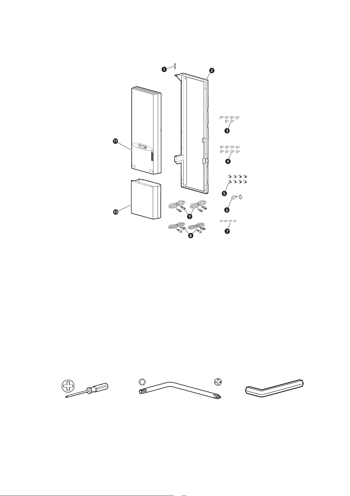
Inventory
na1511a
Item Description Quantity
Hinge pin 1
1
Fan assembly mounting frame
2
NOTE: Narrow frame shown; your frame may differ.
NetShelter SX M6 Phillips rack-mounting screws 6
3
NetShelter VX M6 Phillips rack-mounting screws 8
4
5 Hole plugs 8
6 M6 shoulder hex screw with lock washer 1
7 Fan assembly extension M4 Phillips mounting screws 4
8 Power cords—NEMA 5-15 2
9 Power cords—CEE22 2
: Fan assembly extension 1
; Fan assembly 1
1
Tools required (not provided)
#2 Phillips screwdriver M5 Torx®/Phillips Hex wrench
Receiving inspection
Inspect the package and contents for shipping damage, and make sure that all parts were sent. Report any
damage immediately to the shipping agent. Report missing contents, damage, or other problems
immediately to APC or your APC reseller.
3Rack Air Removal Unit
Installation
ns0617a
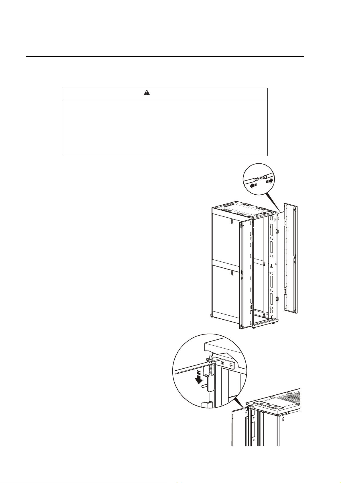
Attach the Mounting Frame
Remove the doors
WARNING
TIPPING OR DAMAGE HAZARD
• To avoid personal injury or damage to the enclosure, one person should support
the door while another person removes it from the frame.
• If the enclosure is not joined to other enclosures, ensure it contains sufficient
weight or has adequate support to prevent it tipping during ARU installation.
Failure to follow these instructions can result in serious injury, or
equipment damage.
1. If necessary, move the enclosure to allow at least 762 mm
(30 in) of clearance at the rear of the enclosure to install
the ARU.
2. Disconnect the grounding wires from each door.
3. Remove the grounding wires from the rack to enable the
ARU to fit properly.
4. Remove the rear doors from the enclosure.
Removing doors from an SX enclosure. Open the door 90
degrees and lift it up and off its hinges.
Removing doors from a VX enclosure.
1. Open the rear doors and pull down on the
spring-loaded hinge pin. Lift the doors
from their frame.
ns026 6a
Rack Air Removal Unit4
 Loading...