


Schneider Electric CL-60E, CL-60A User Manual
CL-60E CL-60A
Conext™ CL-60 PV Inverter
Owner’s Guide
975-0768-01-01 Revision B
03-2017
http://solar.schneider-electric.com


Conext™ CL-60 PV Inverter
Owner’s Guide
http://solar.schneider-electric.com

Copyright © 2017 Schneider Electric. All Rights Reserved. All trademarks are owned by Schneider Electric Industries SAS
or its affiliated companies. Other 3rd party trademarks are owned by their respective companies.
Exclusion for Documentation
U
NLESS SPECIFICALLY AGREED TO IN WRITING, SELLER
(A) MAKES NO WARRANTY AS TO THE ACCURACY, SUFFICIENCY OR SUITABILITY OF ANY TECHNICAL OR OTHER INFORMATION PROVIDED
IN ITS MANUALS OR OTHER DOCUMENTATION;
(
B) ASSUMES NO RESPONSIBILITY OR LIABILITY FOR LOSSES, DAMAGES, COSTS OR EXPENSES, WHETHER SPECIAL, DIRECT, INDIRECT,
CONSEQUENTIAL OR INCIDENTAL, WHICH MIGHT ARISE OUT OF THE USE OF SUCH INFORMATION. THE USE OF ANY SUCH INFORMATION
WILL BE ENTIRELY AT THE USER’S RISK; AND
(C) REMINDS YOU THAT IF THIS MANUAL IS IN ANY LANGUAGE OTHER THAN ENGLISH, ALTHOUGH STEPS HAVE BEEN TAKEN TO
MAINTAIN THE ACCURACY OF THE TRANSLATION, THE ACCURACY CANNOT BE GUARANTEED. APPROVED CONTENT IS CONTAINED WITH
THE ENGLISH LANGUAGE VERSION WHICH IS POSTED AT SOLAR.SCHNEIDER-ELECTRIC.COM.
Document Number: 975-0768-01-01 Revision: Revision B Date: 03-2017
Product Part Numbers: PVSCL60A (CL-60A—North American version)
PVSCL60E (CL-60E—IEC version)
Contact Information: http://solar.schneider-electric.com
Please contact your local Schneider Electric Sales Representative or visit our website at:
http://solar.schneider-electric.com/tech-support/

About This Guide
Purpose
The purpose of this Owner’s Guide is to explain the procedures for operating,
configuring, maintaining, and troubleshooting the Conext CL-60 PV Inverter.
Scope
The Guide provides safety guidelines and general information for installing and
operating the Conext CL-60, as well as information about configuring,
monitoring, and troubleshooting the unit. It does not include information on how
to use other Schneider Electric and third-party products.
Audience
The Guide is intended for use by anyone who plans to design, construct, install,
or operate a system involving the CL-60. The installation information in this guide
is intended for qualified personnel. Qualified personnel have training,
knowledge, and experience in:
• Installing electrical equipment and PV power systems (up to 1000 volts)
• Applying all applicable installation codes
• Analyzing and reducing the hazards involved in performing electrical work
• Selecting and using Personal Protective Equipment (PPE)
975-0768-01-01 Revision B v
About This Guide
Organization
This Guide is organized into:
Chapter 1, “Introduction”
Chapter 2, “Installation”
Chapter 3, “Electrical Connections”
Chapter 4, “Commissioning”
Chapter 5, “LCD Display Operation”
Chapter 6, “Troubleshooting”
Chapter 7, “Disconnecting, Dismantling, and Disposing the CL-60”
Chapter 8, “Specifications”
Abbreviations and Acronyms
Related Information
AFD
EMI
G
GND
HMI
IGBT
LAN / WAN
LCD
LED
NFPA
PE
PPE
PV
SPD
You can find more information about Schneider Electric, as well as its products
and services at http://solar.schneider-electric.com.
Arc Fault Detection device
Electromagnetic Interference
Ground (also referred as Protective Earth)
Human-Machine Interface
Insulated Gate Bipolar Transistor
Local Area Network / Wide Area Network
Liquid Crystal Display (used for HMI displays)
Light Emitting Diode (used for indicator lights)
National Fire Protection Association
Protective Earth (also referred as Ground)
Personal Protective Equipment
Photovoltaic (or Solar)
Surge Protection Device
vi 975-0768-01-01 Revision B
Important Safety Instructions
DANGER
WARNING
CAUTION
NOTICE
READ AND SAVE THESE INSTRUCTIONS - DO NOT DISCARD
This document contains important safety instructions that must be followed
during installation procedures (if applicable). Read and keep this Owner’s Guide
for future reference.
Read these instructions carefully and look at the equipment (if applicable) to
become familiar with the device before trying to install, operate, service or
maintain it. The following special messages may appear throughout this bulletin
or on the equipment to warn of potential hazards or to call attention to information
that clarifies or simplifies a procedure.
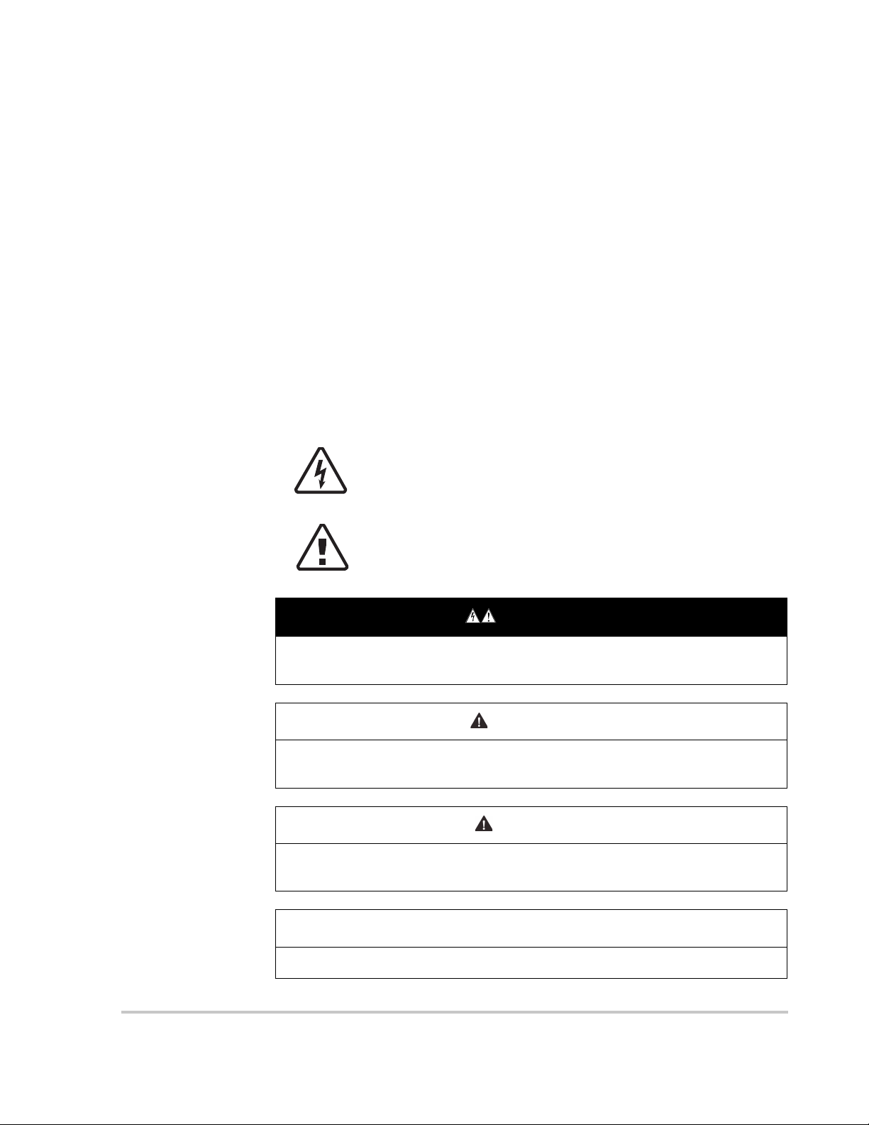
The addition of either symbol to a “Danger” or “Warning” safety
label indicates that an electrical hazard exists which will result
in personal injury if the instructions are not followed.
This is the safety alert symbol. It is used to alert you to potential
personal injury hazards. Obey all safety messages that follow
this symbol to avoid possible injury or death.
DANGER indicates an imminently hazardous situation, which, if not avoided,
will result in death or serious injury.
WARNING indicates a potentially hazardous situation, which, if not avoided,
can result in death or serious injury.
CAUTION indicates a potentially hazardous situation, which, if not avoided,
can result in moderate or minor injury.
NOTICE indicates important information that you need to read carefully.
975-0768-01-01 Revision B vii

Safety
Please Note
Electrical equipment must be installed, operated, serviced, and maintained only
by qualified personnel. No responsibility is assumed by Schneider Electric for
any consequences arising out of the use of this material.
A qualified person is one who has skills and knowledge related to the
construction, installation, and operation of electrical equipment and has received
safety training to recognize and avoid the hazards involved.
Safety Information
1. Before using this product, read all instructions and cautionary markings on
the unit and all appropriate sections of this manual.
2. Use of accessories not recommended or sold by the manufacturer may result
in a risk of fire, electric shock, or injury to persons.
3. The manufacturer recommends that all wiring be done by a certified
technician or electrician to ensure adherence to the local and national
electrical codes applicable in your jurisdiction.
4. To avoid a risk of fire and electric shock, make sure that existing wiring is in
good condition and that wire is not undersized. Do not operate the
equipment with damaged or substandard wiring.
5. Do not operate the equipment if it has been damaged in any way.
6. Do not disassemble the Conext CL-60 except where noted for connecting
wiring and cabling. See your warranty for instructions on obtaining service.
Attempting to service the unit yourself may result in a risk of electrical shock
or fire.
7. To reduce the risk of electrical shock, disconnect the power supply from the
equipment before attempting installation, and any maintenance (including
cleaning or working on any components connected to the equipment).
Internal capacitors remain charged for ten minutes after all power is
disconnected.
8. The equipment must be grounded. Use the protective grounding conductor
provided with the AC input conductors.
9. This product is designed for outdoor use and is rated IP65 and Type 4X.
10. To reduce the chance of short-circuits, always use insulated tools when
installing or working with this equipment. Do not leave tools inside.
11. Remove personal metal items such as rings, bracelets, necklaces, and
watches when working with electrical equipment.
12. Do not open nor disassemble the top half of the unit. There are no userserviceable parts inside.
13. To disconnect the unit from DC power, turn the DC switch to OFF and then
remove all PV string connectors from the DC terminals.
viii 975-0768-01-01 Revision B
Safety
DANGER
NOTICE
ELECTRIC SHOCK, EXPLOSION, OR ARC FLASH HAZARDS
• Apply appropriate personal protective equipment (PPE) and follow safe
electrical work practices.
• This equipment must only be installed and serviced by qualified electrical
personnel.
• Never energize the inverter with the covers removed.
• Do not open fuse holders under load. The fuse must be de-energized from
all sources before servicing.
• The inverter is energized from multiple sources. Before removing covers
identify all source, de-energize, lock-out, and tag-out and wait 10 minutes.
• Always use a properly rated voltage sensing device to confirm all circuits
are de-energized.
• Replace all devices and covers before turning on power to this equipment.
• The DC conductors of this photovoltaic system are ungrounded and may
be energized.
Failure to follow these instructions will result in death or serious injury.
Access to live parts shall be limited to suitably qualified electrical personnel. See
installation instructions before connecting to the supply.
EQUIPMENT DAMAGE
• All cables connected to the CL-60 must run through the cable glands on
the unit.
• This unit is susceptible to damage from EMI and nearby lightning strikes
unless a surge protection device (a lightning arrestor) is installed.
• Turn Off all devices before connecting cables.
• Use the CL-60’s DC switch as its On/Off switch.
• To isolate the CL-60, follow “Lock-Out Tag-Out (LOTO) Procedure” on
page xi.
Failure to follow these instructions can damage equipment or affect
network performance.
975-0768-01-01 Revision B ix

Safety
Storage Information
Store the inverter properly when the inverter is not to be installed immediately.
1. Inverter must be packed inside its original carton with the desiccant bags
inside.
2. Store the inverter with its front panel facing up. The carton should lay flat and
parallel to the ground.
3. Seal the carton with standard packaging tape.
4. Store the inverter in a dry and clean place to protect it against dust and
moisture.
5. Temperature: -30 to 85 °C (-22 to 185 ºF)
Relative humidity: 0 to 100%.
6. Do not stack more than two inverters on top of another.
7. Keep the inverter away from chemically corrosive materials.
8. Periodically check for any visible damages to the carton and inspect the
inverter right away if the carton shows signs of penetration during the storage
period. Replace the carton, if necessary.
NOTE: A thorough and professional inspection may be required before
installing the inverter after more than six months in storage. Contact a local
Schneider Electric sales representative for information on how to arrange the
inspection.
IMPORTANT: Storage beyond two years voids the warranty.
x 975-0768-01-01 Revision B
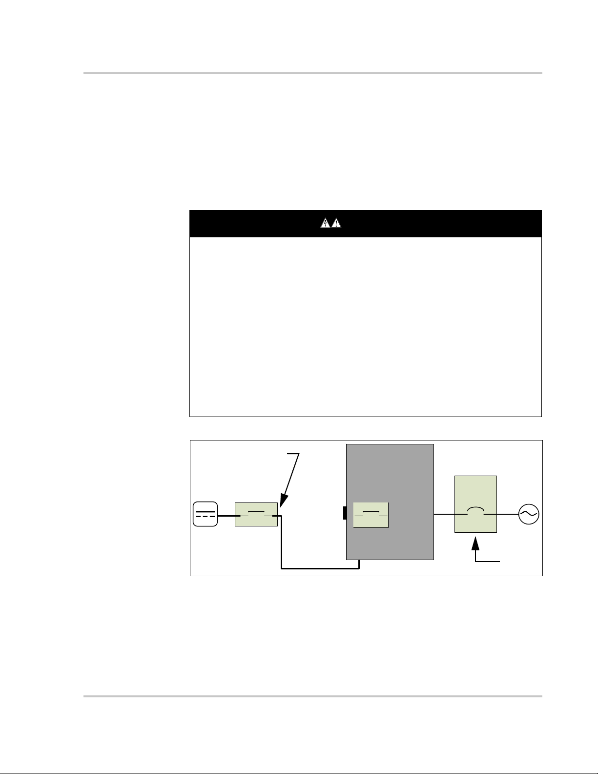
Lock-Out Tag-Out (LOTO) Procedure
DANGER
CL-60
Mains
AC Panel
Breaker
DC Disconnect Device
LOTO
LOTO
DC Switch
PV string
Lock-out refers to the practice of preventing de-energized circuits from being reenergized by putting locks on the disconnecting devices, holding them open.
Tag-out refers to the practice of attaching a tag to the disconnect-device locks
warning others not to operate the disconnect device and containing information
relating to the lock-out, such as the person responsible, the reason, and the date
and time. Combined these two practices are called the lock-out and tag-out
(LOTO) procedure.
ELECTRIC SHOCK, EXPLOSION, OR ARC FLASH HAZARDS
• Apply appropriate personal protective equipment (PPE) and follow safe
electrical work practices.
• This equipment must only be installed and serviced by qualified electrical
personnel.
• Never energize the inverter with the covers removed.
• Always use a properly rated voltage sensing device to confirm all circuits
are de-energized.
• Replace all devices and covers before turning on power to this equipment.
• The inverter is energized from multiple sources. Before opening the cover
identify the power source (see A), de-energize (see B), lock-out and tagout (see C), and wait ten minutes for circuits to discharge (see D).
Failure to follow these instructions will result in death or serious injury.
Safety
Figure 1-1 Single Line Diagram for CL-60
A 1. Identify any disconnect device upstream from the CL-60 unit.
B 2. Open the disconnect device that connects to the CL-60 to cut off DC power.
C 3. Turn the CL-60’s DC Switch to OFF position.
4. Lock-out and tag out the external DC disconnect device.
5. Remove all PV string connectors from the DC terminals.
975-0768-01-01 Revision B xi

Safety
A 6. Identify the AC Panel Breaker downstream from the CL-60 unit.
B 7. Open the AC Panel door.
8. Turn Off the AC Panel Breaker (open the switch) that connects to the CL-60
to cut off AC power.
9. Close the AC Panel door.
C 10. Lock-out and tag out the AC Panel.
D 11. Wait ten minutes for the circuits in the CL-60 to discharge.
12. Check that the inverter is in zero energy state before performing work.
13. Open the CL-60 enclosure and commence service and maintenance
activities.
xii 975-0768-01-01 Revision B

Contents
Important Safety Instructions
Safety Information - - - - - - - - - - - - - - - - - - - - - - - - - - - - - - - - - - - - - - - - - - - - - - - - - - - - - - - - - viii
Storage Information - - - - - - - - - - - - - - - - - - - - - - - - - - - - - - - - - - - - - - - - - - - - - - - - - - - - - - - - - x
Lock-Out Tag-Out (LOTO) Procedure - - - - - - - - - - - - - - - - - - - - - - - - - - - - - - - - - - - - - - - - - - - -xi
1 Introduction
Conext CL-60 - - - - - - - - - - - - - - - - - - - - - - - - - - - - - - - - - - - - - - - - - - - - - - - - - - - - - - - - - - - - 1–2
Physical Features - - - - - - - - - - - - - - - - - - - - - - - - - - - - - - - - - - - - - - - - - - - - - - - - - - - - - - - - - 1–4
Dimensions - - - - - - - - - - - - - - - - - - - - - - - - - - - - - - - - - - - - - - - - - - - - - - - - - - - - - - - - - - 1–5
Inverter Dimensions - - - - - - - - - - - - - - - - - - - - - - - - - - - - - - - - - - - - - - - - - - - - - - - - - 1–5
Packaging Box Dimensions - - - - - - - - - - - - - - - - - - - - - - - - - - - - - - - - - - - - - - - - - - - - 1–5
Product Label - - - - - - - - - - - - - - - - - - - - - - - - - - - - - - - - - - - - - - - - - - - - - - - - - - - - - - 1–6
LCD Display - - - - - - - - - - - - - - - - - - - - - - - - - - - - - - - - - - - - - - - - - - - - - - - - - - - - - - - - - - 1–7
DC Switch - - - - - - - - - - - - - - - - - - - - - - - - - - - - - - - - - - - - - - - - - - - - - - - - - - - - - - - - - - - 1–8
Technical Features - - - - - - - - - - - - - - - - - - - - - - - - - - - - - - - - - - - - - - - - - - - - - - - - - - - - - - - - 1–9
CL-60 Circuit Diagram - - - - - - - - - - - - - - - - - - - - - - - - - - - - - - - - - - - - - - - - - - - - - - - - - - - 1–9
Standard Features - - - - - - - - - - - - - - - - - - - - - - - - - - - - - - - - - - - - - - - - - - - - - - - - - - - - - 1–9
Derating Feature - - - - - - - - - - - - - - - - - - - - - - - - - - - - - - - - - - - - - - - - - - - - - - - - - - - - - - 1–10
2 Installation
Pre-Installation - - - - - - - - - - - - - - - - - - - - - - - - - - - - - - - - - - - - - - - - - - - - - - - - - - - - - - - - - - - 2–2
Planning the Installation - - - - - - - - - - - - - - - - - - - - - - - - - - - - - - - - - - - - - - - - - - - - - - - - - - 2–2
Installation - - - - - - - - - - - - - - - - - - - - - - - - - - - - - - - - - - - - - - - - - - - - - - - - - - - - - - - - - - - - - - 2–3
What’s In The Box - - - - - - - - - - - - - - - - - - - - - - - - - - - - - - - - - - - - - - - - - - - - - - - - - - - - - - 2–3
Material and Tools - - - - - - - - - - - - - - - - - - - - - - - - - - - - - - - - - - - - - - - - - - - - - - - - - - - - - - 2–4
Location Information - - - - - - - - - - - - - - - - - - - - - - - - - - - - - - - - - - - - - - - - - - - - - - - - - - - - 2–4
Install and Mount the CL-60 - - - - - - - - - - - - - - - - - - - - - - - - - - - - - - - - - - - - - - - - - - - - - - - 2–8
Torque Values - - - - - - - - - - - - - - - - - - - - - - - - - - - - - - - - - - - - - - - - - - - - - - - - - - - - - - - 2–15
3 Electrical Connections
Precautions - - - - - - - - - - - - - - - - - - - - - - - - - - - - - - - - - - - - - - - - - - - - - - - - - - - - - - - - - - - - - 3–2
Planning the Electrical Connections - - - - - - - - - - - - - - - - - - - - - - - - - - - - - - - - - - - - - - - - - 3–2
Cabling and Wiring - - - - - - - - - - - - - - - - - - - - - - - - - - - - - - - - - - - - - - - - - - - - - - - - - - - - - - - - 3–3
Material and Tools - - - - - - - - - - - - - - - - - - - - - - - - - - - - - - - - - - - - - - - - - - - - - - - - - - - - - - 3–3
Terminal and Cable Entry Points (for CL-60E) - - - - - - - - - - - - - - - - - - - - - - - - - - - - - - - - - - 3–5
Terminal and Cable Entry Points (for CL-60A) - - - - - - - - - - - - - - - - - - - - - - - - - - - - - - - - - - 3–6
AC Side Cable Connection - - - - - - - - - - - - - - - - - - - - - - - - - - - - - - - - - - - - - - - - - - - - - - - 3–7
AC Side Requirements - - - - - - - - - - - - - - - - - - - - - - - - - - - - - - - - - - - - - - - - - - - - - - - 3–7
AC Circuit Breaker - - - - - - - - - - - - - - - - - - - - - - - - - - - - - - - - - - - - - - - - - - - - - - - - - - 3–7
Residual Current Device - - - - - - - - - - - - - - - - - - - - - - - - - - - - - - - - - - - - - - - - - - - - - - 3–7
975-0768-01-01 Revision B xiii

Contents
Multiple Inverters in Parallel Connection - - - - - - - - - - - - - - - - - - - - - - - - - - - - - - - - - - - 3–8
Grid Connection - - - - - - - - - - - - - - - - - - - - - - - - - - - - - - - - - - - - - - - - - - - - - - - - - - - - 3–9
PV Array Connection - - - - - - - - - - - - - - - - - - - - - - - - - - - - - - - - - - - - - - - - - - - - - - - - - - - 3–14
PV Input Configuration - - - - - - - - - - - - - - - - - - - - - - - - - - - - - - - - - - - - - - - - - - - - - - 3–14
PV Input Connection - - - - - - - - - - - - - - - - - - - - - - - - - - - - - - - - - - - - - - - - - - - - - - - - 3–16
Grounding the Inverter - - - - - - - - - - - - - - - - - - - - - - - - - - - - - - - - - - - - - - - - - - - - - - - - - 3–21
Grounding System Overview - - - - - - - - - - - - - - - - - - - - - - - - - - - - - - - - - - - - - - - - - - 3–21
Second Protective Earth Terminal - - - - - - - - - - - - - - - - - - - - - - - - - - - - - - - - - - - - - - 3–22
Communication Connection - - - - - - - - - - - - - - - - - - - - - - - - - - - - - - - - - - - - - - - - - - - - - - - - 3–23
Overview - - - - - - - - - - - - - - - - - - - - - - - - - - - - - - - - - - - - - - - - - - - - - - - - - - - - - - - - - - - 3–23
RS-485 Communication System - - - - - - - - - - - - - - - - - - - - - - - - - - - - - - - - - - - - - - - - - - - 3–24
Ethernet Connection - - - - - - - - - - - - - - - - - - - - - - - - - - - - - - - - - - - - - - - - - - - - - - - - - - - 3–28
4 Commissioning
Inspection Before Commissioning - - - - - - - - - - - - - - - - - - - - - - - - - - - - - - - - - - - - - - - - - - - - - 4–2
Commissioning Procedure - - - - - - - - - - - - - - - - - - - - - - - - - - - - - - - - - - - - - - - - - - - - - - - - - - 4–2
5 LCD Display Operation
Description of the Selection Buttons - - - - - - - - - - - - - - - - - - - - - - - - - - - - - - - - - - - - - - - - - - - 5–2
Menu Tree - - - - - - - - - - - - - - - - - - - - - - - - - - - - - - - - - - - - - - - - - - - - - - - - - - - - - - - - - - - - - - 5–3
Main Screen - - - - - - - - - - - - - - - - - - - - - - - - - - - - - - - - - - - - - - - - - - - - - - - - - - - - - - - - - - - - 5–4
Contrast Adjustment - - - - - - - - - - - - - - - - - - - - - - - - - - - - - - - - - - - - - - - - - - - - - - - - - - - - - - - 5–6
Checking Running Information - - - - - - - - - - - - - - - - - - - - - - - - - - - - - - - - - - - - - - - - - - - - - - - 5–6
Checking History Information - - - - - - - - - - - - - - - - - - - - - - - - - - - - - - - - - - - - - - - - - - - - - - - - 5–8
Checking Running Records - - - - - - - - - - - - - - - - - - - - - - - - - - - - - - - - - - - - - - - - - - - - - - - 5–8
Checking Fault (Event) Records - - - - - - - - - - - - - - - - - - - - - - - - - - - - - - - - - - - - - - - - - - - 5–8
Checking History Event Records - - - - - - - - - - - - - - - - - - - - - - - - - - - - - - - - - - - - - - - - - - - 5–9
Checking Energy Records - - - - - - - - - - - - - - - - - - - - - - - - - - - - - - - - - - - - - - - - - - - - - - - 5–9
Starting/Stopping - - - - - - - - - - - - - - - - - - - - - - - - - - - - - - - - - - - - - - - - - - - - - - - - - - - - - - - - 5–10
Password Entry - - - - - - - - - - - - - - - - - - - - - - - - - - - - - - - - - - - - - - - - - - - - - - - - - - - - - - - - - 5–11
System Parameter Setting - - - - - - - - - - - - - - - - - - - - - - - - - - - - - - - - - - - - - - - - - - - - - - - - - - 5–12
Language Setting - - - - - - - - - - - - - - - - - - - - - - - - - - - - - - - - - - - - - - - - - - - - - - - - - - - - - 5–12
Time Setting - - - - - - - - - - - - - - - - - - - - - - - - - - - - - - - - - - - - - - - - - - - - - - - - - - - - - - - - - 5–12
Total Energy Deviation Adjustment - - - - - - - - - - - - - - - - - - - - - - - - - - - - - - - - - - - - - - - - - 5–13
Load Default (Factory Reset) - - - - - - - - - - - - - - - - - - - - - - - - - - - - - - - - - - - - - - - - - - - - - 5–14
Checking Firmware Version - - - - - - - - - - - - - - - - - - - - - - - - - - - - - - - - - - - - - - - - - - - - - - 5–14
Running Parameter Setting - - - - - - - - - - - - - - - - - - - - - - - - - - - - - - - - - - - - - - - - - - - - - - - - - 5–15
Main Screen of Run-param - - - - - - - - - - - - - - - - - - - - - - - - - - - - - - - - - - - - - - - - - - - - - - 5–15
Active/Reactive Power Parameters - - - - - - - - - - - - - - - - - - - - - - - - - - - - - - - - - - - - - - - - - 5–18
Reactive Power Regulation - - - - - - - - - - - - - - - - - - - - - - - - - - - - - - - - - - - - - - - - - - - - - - 5–18
Pf Mode - - - - - - - - - - - - - - - - - - - - - - - - - - - - - - - - - - - - - - - - - - - - - - - - - - - - - - - - - 5–18
Qt Mode - - - - - - - - - - - - - - - - - - - - - - - - - - - - - - - - - - - - - - - - - - - - - - - - - - - - - - - - 5–19
Off Mode - - - - - - - - - - - - - - - - - - - - - - - - - - - - - - - - - - - - - - - - - - - - - - - - - - - - - - - - 5–19
Q(P) Mode (when the country selection is not “IT”) - - - - - - - - - - - - - - - - - - - - - - - - - - 5–19
xiv 975-0768-01-01 Revision B

Q(U) Mode (when the country selection is not “IT”) - - - - - - - - - - - - - - - - - - - - - - - - - - 5–20
Reactive Power Setting for Italy - - - - - - - - - - - - - - - - - - - - - - - - - - - - - - - - - - - - - - - - - - - 5–22
Italy Q(P) Mode - - - - - - - - - - - - - - - - - - - - - - - - - - - - - - - - - - - - - - - - - - - - - - - - - - - - 5–22
Italy Q(U) Mode - - - - - - - - - - - - - - - - - - - - - - - - - - - - - - - - - - - - - - - - - - - - - - - - - - - 5–23
Save P/Q-set - - - - - - - - - - - - - - - - - - - - - - - - - - - - - - - - - - - - - - - - - - - - - - - - - - - - - - - - 5–25
Time Parameters - - - - - - - - - - - - - - - - - - - - - - - - - - - - - - - - - - - - - - - - - - - - - - - - - - - - - - 5–25
LVRT Parameter - - - - - - - - - - - - - - - - - - - - - - - - - - - - - - - - - - - - - - - - - - - - - - - - - - - - - - 5–26
Derating Parameters - - - - - - - - - - - - - - - - - - - - - - - - - - - - - - - - - - - - - - - - - - - - - - - - - - - 5–26
ISO Parameters - - - - - - - - - - - - - - - - - - - - - - - - - - - - - - - - - - - - - - - - - - - - - - - - - - - - - - 5–27
Protection Parameter Setting - - - - - - - - - - - - - - - - - - - - - - - - - - - - - - - - - - - - - - - - - - - - - - - - 5–27
Country Setting - - - - - - - - - - - - - - - - - - - - - - - - - - - - - - - - - - - - - - - - - - - - - - - - - - - - - - - 5–28
Single-stage Protection Parameter Setting - - - - - - - - - - - - - - - - - - - - - - - - - - - - - - - - - - - 5–30
Multi-stage Protection Parameter Setting - - - - - - - - - - - - - - - - - - - - - - - - - - - - - - - - - - - - - 5–30
Protection Recovery Setting - - - - - - - - - - - - - - - - - - - - - - - - - - - - - - - - - - - - - - - - - - - - - - 5–32
Protection Parameter Confirmation - - - - - - - - - - - - - - - - - - - - - - - - - - - - - - - - - - - - - - - - - 5–32
Communication Parameter Setting - - - - - - - - - - - - - - - - - - - - - - - - - - - - - - - - - - - - - - - - - - - - 5–33
6 Troubleshooting
Troubleshooting - - - - - - - - - - - - - - - - - - - - - - - - - - - - - - - - - - - - - - - - - - - - - - - - - - - - - - - - - - 6–2
LED Indicator - - - - - - - - - - - - - - - - - - - - - - - - - - - - - - - - - - - - - - - - - - - - - - - - - - - - - - - - - 6–3
LCD Screen - - - - - - - - - - - - - - - - - - - - - - - - - - - - - - - - - - - - - - - - - - - - - - - - - - - - - - - - - - 6–4
Maintenance - - - - - - - - - - - - - - - - - - - - - - - - - - - - - - - - - - - - - - - - - - - - - - - - - - - - - - - - - - - 6–10
Routine Maintenance - - - - - - - - - - - - - - - - - - - - - - - - - - - - - - - - - - - - - - - - - - - - - - - - - - - 6–10
Maintenance Instructions - - - - - - - - - - - - - - - - - - - - - - - - - - - - - - - - - - - - - - - - - - - - - - - - 6–11
Fan Maintenance - - - - - - - - - - - - - - - - - - - - - - - - - - - - - - - - - - - - - - - - - - - - - - - - - - 6–11
Replacing the Fuse - - - - - - - - - - - - - - - - - - - - - - - - - - - - - - - - - - - - - - - - - - - - - - - - - 6–13
Replacing an Expended DC SPD - - - - - - - - - - - - - - - - - - - - - - - - - - - - - - - - - - - - - - - 6–14
Cleaning the Air Inlet and Outlet - - - - - - - - - - - - - - - - - - - - - - - - - - - - - - - - - - - - - - - - 6–15
Contents
7 Disconnecting, Dismantling, and Disposing the CL-60
Disconnecting the CL-60 - - - - - - - - - - - - - - - - - - - - - - - - - - - - - - - - - - - - - - - - - - - - - - - - - - - - 7–2
Dismantling the CL-60- - - - - - - - - - - - - - - - - - - - - - - - - - - - - - - - - - - - - - - - - - - - - - - - - - - - - - 7–4
Disposing the CL-60 - - - - - - - - - - - - - - - - - - - - - - - - - - - - - - - - - - - - - - - - - - - - - - - - - - - - - - - 7–5
8 Specifications
Product Specifications - - - - - - - - - - - - - - - - - - - - - - - - - - - - - - - - - - - - - - - - - - - - - - - - - - - - - 8–2
975-0768-01-01 Revision B xv

xvi

1 Introduction
Chapter 1 contains general information about:
• Conext CL-60
• Physical Features
• Technical Features
975-0768-01-01 Revision B 1–1
Introduction
WARNING
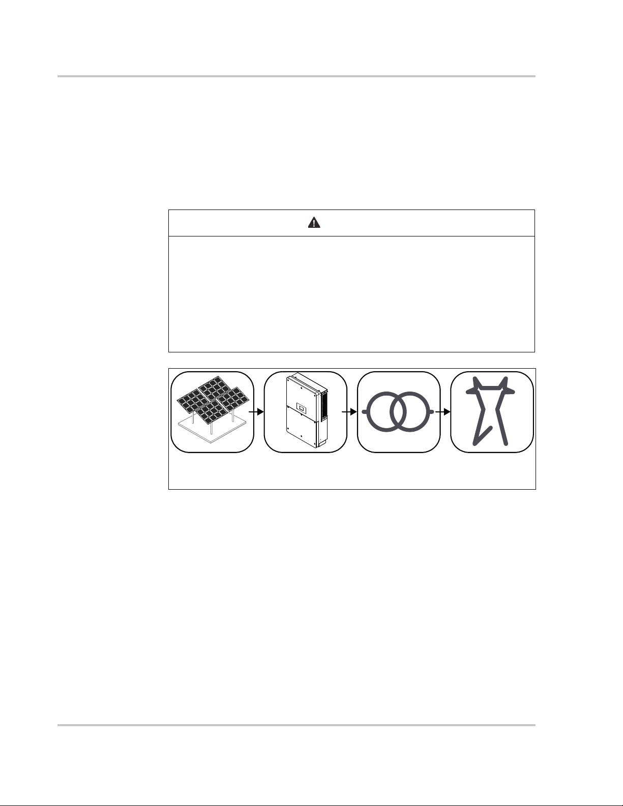
PV Array CL-60 Transformer Utility Grid
TT, TN-C, TN-S,
TN-C-S, IT
without grounding
Conext CL-60
The Conext CL-60 (also referred to as CL-60 PV Inverter) is a transformerless
three-phase PV string inverter that is designed to be an integral part of any utility
grid-connected PV Power System.
The Conext CL-60 is designed to convert DC power generated from the PV array
into AC power that is compatible with utility grade AC power. The following
diagram illustrates its fundamental application.
ELECTRICAL SHOCK HAZARD
• Do not connect the inverter to a PV string where the positive and negative
terminals of the PV strings need to be grounded.
• Do not connect any local load between the inverter and the AC circuit
breaker.
• Use the inverter ONLY in a grid-connected PV system.
Failure to follow these instructions can result in death or serious injury.
Figure 1-1 Fundamental Application
1–2 975-0768-01-01 Revision B
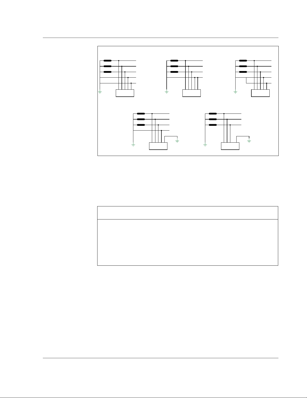
Figure 1-2 Type of Grid Connections
L1
L2
L3
N
PE
CL 60
transformer
TT
L1
L2
L3
N
PE
PE
CL 60
transformer
TN-S
L1
L2
L3
N
PE
PE
CL 60
transformer
TN-C-S
L1
L2
L3
PEN
PE
CL 60
transformer
TN-C
L1
L2
L3
PE
CL 60
transformer
IT
NOTICE
Conext CL-60
Grid Connection
Conditions
More than one CL-60 PV Inverter can be connected to the PV system if the total
capacity of the PV system (PV array) exceeds the capacity of a single inverter.
Each inverter in the multiple setup connects individually to a PV string at the
inverter’s DC input side. Then the inverter’s AC output side connects to the AC
mains (the grid).
EQUIPMENT DAMAGE
Follow local regulations when installing a connection to a either a TT or TN
system. An additional external Type B RCD (residual current detection) device
rated 300 mA continuous may be required and combined with additional
automatic disconnect devices.
Failure to follow these instructions can result in equipment damage.
975-0768-01-01 Revision B 1–3
Introduction
1
2
4
3
3
6
8
7
3
3
5
9
10
11
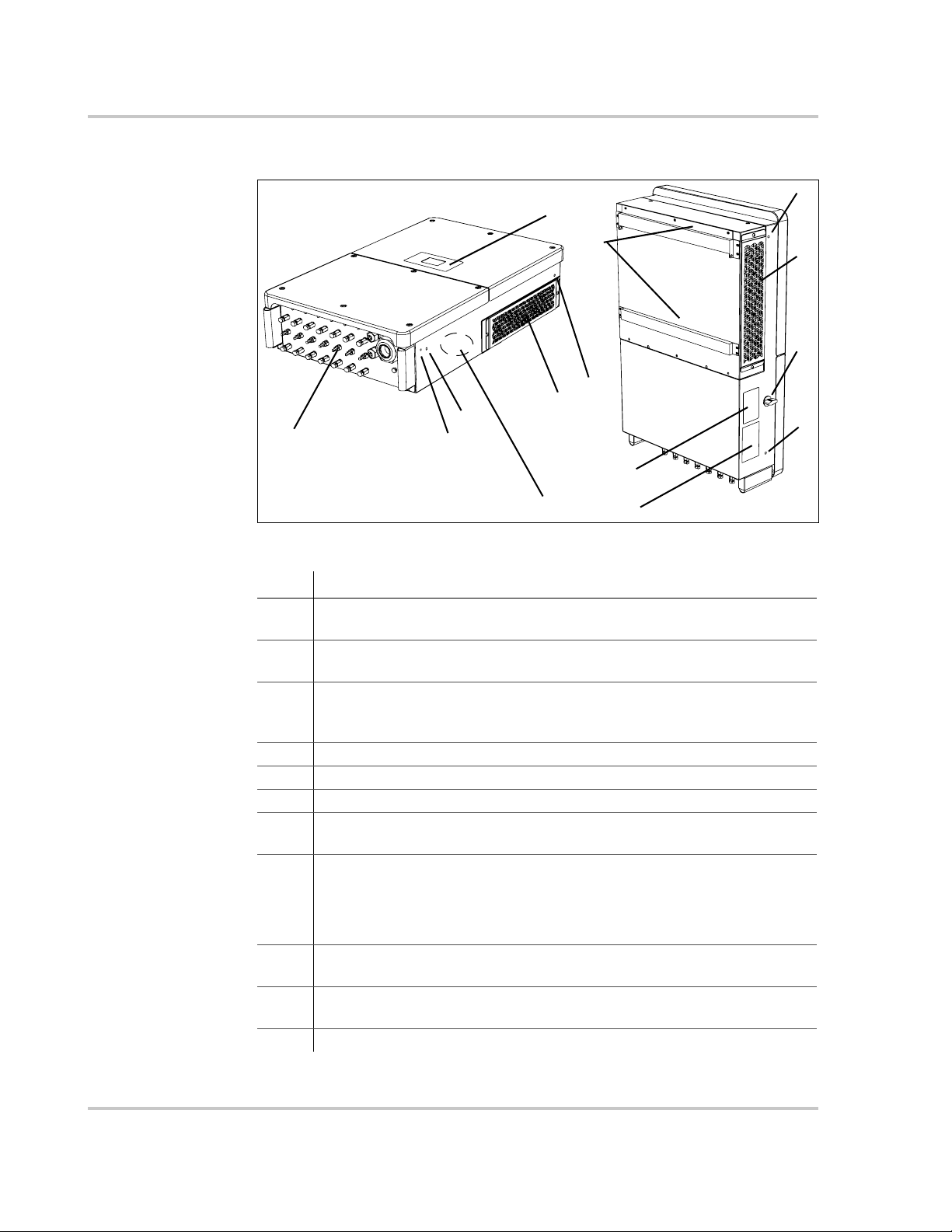
Physical Features
Figure 1-3 CL-60 Components (CL-60E shown)
Item Description
1 LCD Display is the main HMI for viewing operational information and
changing parameter values for settings.
2 Electrical connection area includes the DC terminals, AC terminals,
and RS-485 communication terminals.
3 Hole Inserts for Screw-in Handles are used for seating the screw-in
handles. The handles are used for moving, handling, and mounting the
PV Inverter.
4 PE second terminal
5 Air ventilation is equipped with fans to draw hot air out.
6Backplate is used to hang the PV Inverter onto the wall.
7 Fans (3x) with protective grate are used for forced-air cooling inside
the inverter enclosure.
8 DC switch is a protective component for safely disconnecting DC
power from the PV Array but only up to the terminals.
For full disconnection, disconnect power from the PV disconnect
device. See “Single Line Diagram for CL-60” on page xi.
9 Warning Label Read before installing, maintaining, and servicing the
10 Rating Label contains the unit’s electrical specifications and regulatory
11 CL-60A has an AC Switch in the area shown.
unit.
markings.
1–4 975-0768-01-01 Revision B
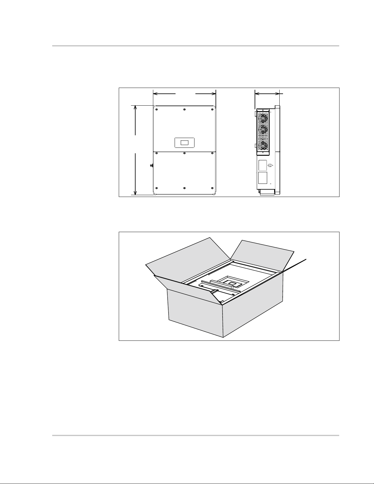
Dimensions
625 mm
24.6 in
250 mm
9.8 in
991 mm
39 in
Unit weight:
66.0 kg (CL-60E)
147 lbs (CL-60A)
Length:
1160 mm / 45.7 inWidth:
770 mm / 30.3 in
Height:
375 mm / 14.8 in
Gross weight:
76.0 kg (CL-60E)
168 lbs (CL-60A)
Inverter Dimensions
Physical Features
Figure 1-4 Conext CL-60 Dimensions (CL-60E shown)
Packaging Box Dimensions
Figure 1-5 Conext CL-60 Packaging Box Dimensions
975-0768-01-01 Revision B 1–5
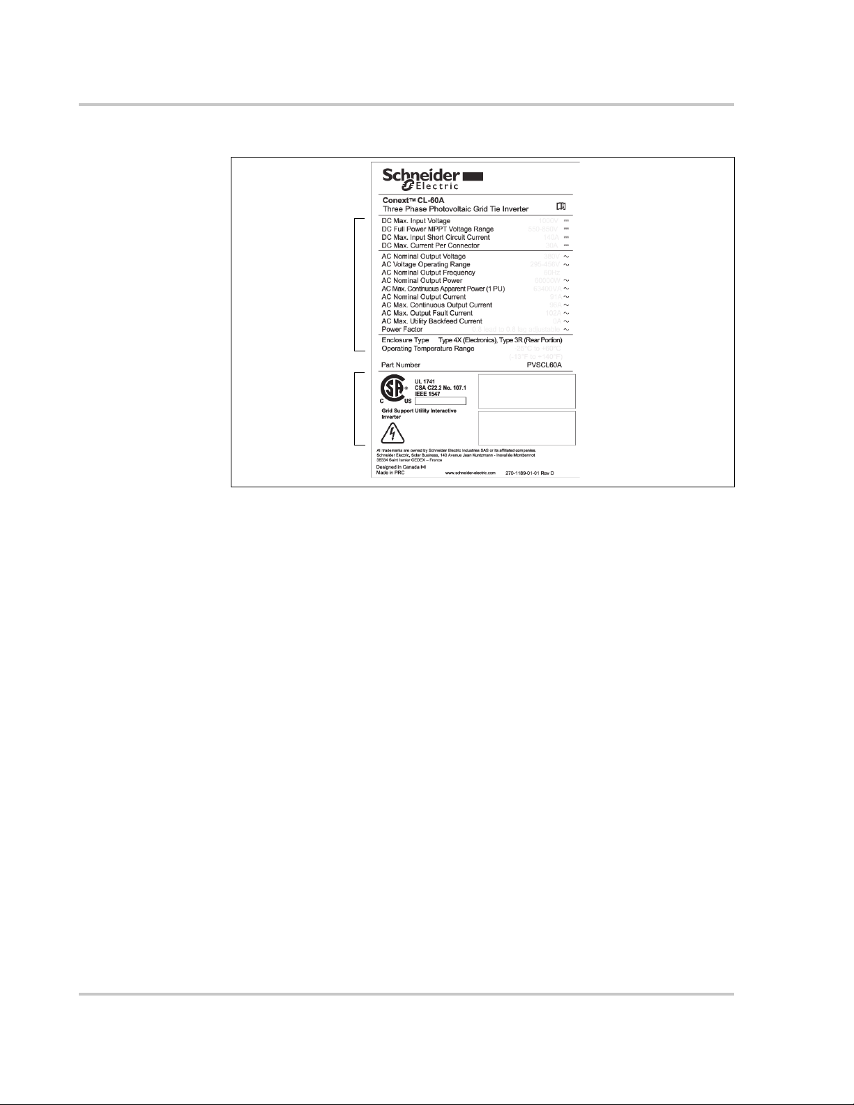
Introduction
product name
product ratings
product part number
certification and
regulatory
markings
serial number
manufacturing
date
Product Label
Figure 1-6 Example of a Conext CL-60 Product Label
1–6 975-0768-01-01 Revision B
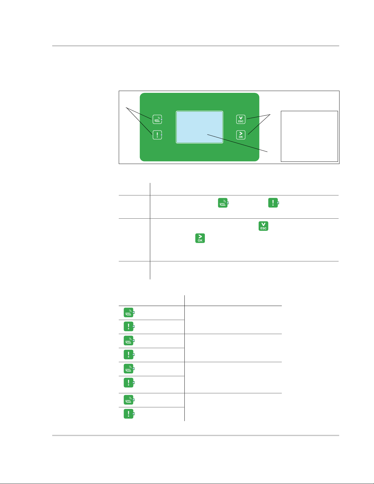
LCD Display
1
2
3
NOTE: Condensation may
appear behind the LCD
display. This occurrence is
normal in cold climate
conditions. The
condensation dissipates
soon after the unit starts
producing power or when
ambient temperature settles
above the dew point.
Physical Features
The LCD Display is the main interface of the CL-60 PV Inverter. It is made up of
two LED indicators, two buttons, and the screen itself.
Figure 1-7 LCD Display
Item Description
1
LED Indicators – RUN and ALERT .
Indicates the present operational state of the PV Inverter.
2
Selection Buttons – ESC (and down) and
OK (and next) .
Use for navigating the LCD interface, selecting settings, and
changing parameters of settings.
3 LCD Screen. Displays the present state of the PV Inverter,
operational and alarm information, and present settings.
Tab l e 1 -1 Description of LED Indicators
LED Indicators Description
RUN - On
The PV Inverter is in operation.
ALERT - Off
RUN - Off
A ground fault (or any event) is
detected or a protection feature is
ALERT - On
RUN - Off
ALERT - Off
enabled.
The PV Inverter is not in operation
or a communication fault is
detected between the DSP and
the LCD Display.
RUN - flashing
ALERT - Off
975-0768-01-01 Revision B 1–7
The PV Inverter is communicating
a warning.
Introduction
WARNING
DC Switch
The DC Switch is both the main power switch and a protective component which
is used to safely disconnect DC power between the PV array and the PV Inverter
whenever necessary to do so.
The PV Inverter operates automatically (without the need of switching On or Off)
when DC input and AC output requirements are continuously met. Turn the DC
switch to the Off position only to stop PV Inverter operation when a ground fault
condition is detected or when there is a non-ground fault condition to stop
inverter operation such as maintenance and servicing.
ELECTRIC SHOCK HAZARD
• Do not perform maintenance and servicing without totally disconnecting
the DC source from the inverter. The DC switch does not de-energize the
DC fuse circuits. The fuse circuits remain live even if the DC switch is
turned to the Off position.
• To remove power to the inverter, disconnect power from the PV disconnect
device. See “Single Line Diagram for CL-60” on page xi.
• Alternatively, to remove power to the inverter, open all MC4 type connectors
using a special tool for disconnection.
Failure to follow these instructions can result in death or serious injury.
NOTE: For CL-60A, the DC switch is provided with a lockable twisting knob to
meet the NFPA 70E standard.
1–8 975-0768-01-01 Revision B
Technical Features
LCD/RS485
DSP+CPLD
DC
L1
L2
L3
N
PE
NL3L2L1
PE
DC
DC In
+-
+-
NL3L2
L1
PE
DC
DC In
+-
+-
L1 L2 L3
N
L1 L2 L3
N
DC EMI
Filter
DC bus
Inversion
circuit
AC
EMI
Filter
AC
Reactor
Relay
Fan
AC SPD
DC
switch
AC
switch
DC SPD
Current detection
DC SPD
DC
switch
DC fuse
DC fuse
Auxilia ry
power circuit
Current detection
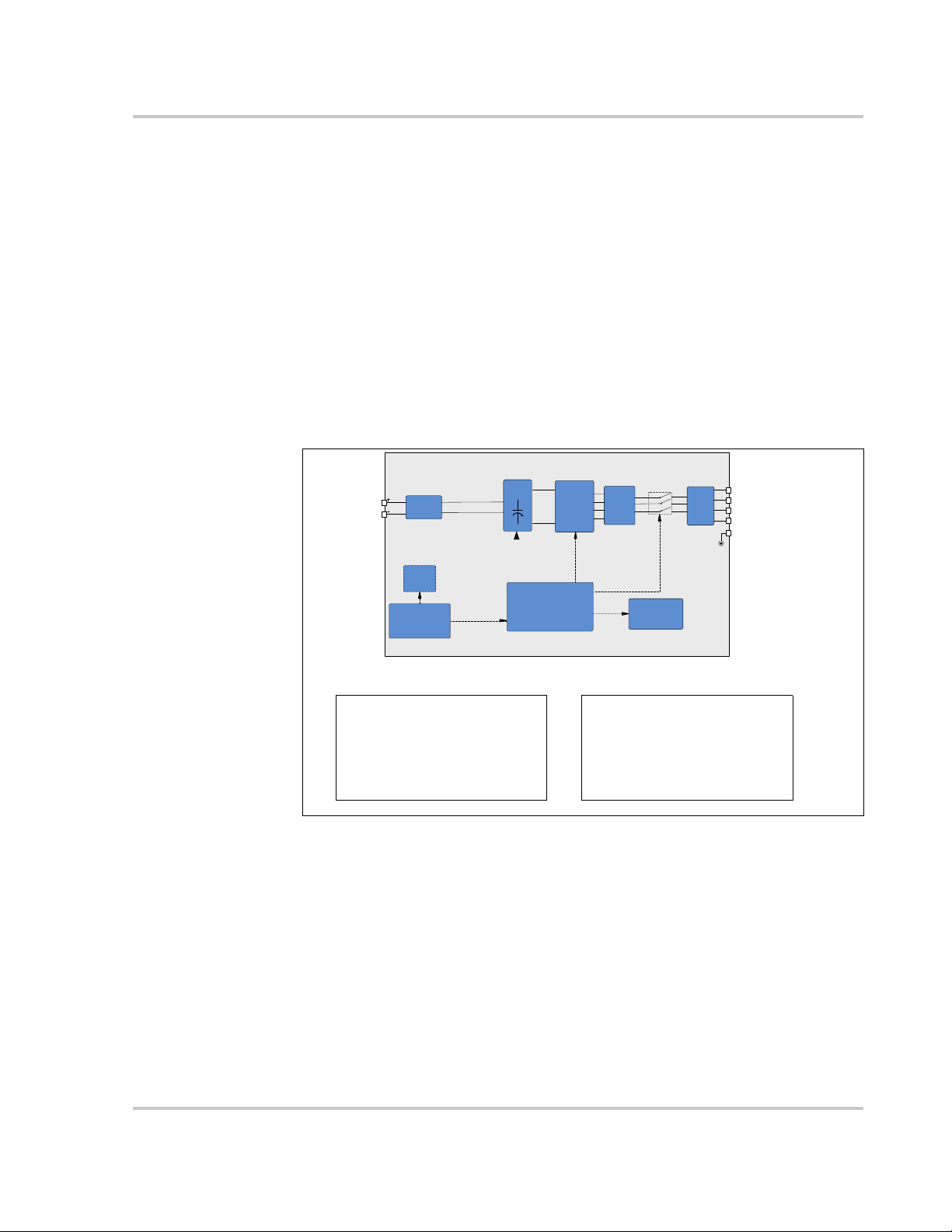
CL-60E Wiring Box contents CL-60A Wiring Box contents
- DC switch
- 14 strings
- 15A fuses in positive polarity
- monitoring in negative polarity
- type 2 DC SPD
- type 3 AC SPD
- DC switch
- 8 inputs (1@ for 2 combined strings)
- 30A fuses in both polarities
- type 2 DC SPD
- type 3 AC SPD
- AC switch
CL-60 Circuit Diagram
Figure 1-8 shows the main circuit of the PV Inverter.
Maximum Power Point Tracking (MPPT) is utilized to optimize harvesting DC
power from the PV array with different PV input conditions.
The PV Inverter circuit converts DC power into AC power and feeds it to the utility
grid through the inverter’s AC terminal. The protection circuit is equipped to
ensure the device’s safe operation and personal safety.
The DC switch is used to disconnect DC power from the PV Array safely.
The inverter provides standard RS-485 ports for communication.
Technical Features
Figure 1-8 Conext CL-60 Circuit Diagram
Standard Features
Inverter Function The device’s main function is to convert DC current into grid-
compatible AC current then feed this current into the grid.
Data Storage and LCD Display The onboard memory stores information such
as fault detection and displays them on the screen of the integrated LCD Display.
Device Configuration The LCD Display provides the main interface for
accessing device settings and changing them for optimal operation of the
inverter.
975-0768-01-01 Revision B 1–9

Introduction
Communication Interface Features a standard RS-485 port which can be
connected with a monitoring device such as a power meter,
Protection Features The unit is equipped with the following features for
preventing inverter damage, other equipment damage, and personal injury
hazards.
• Short-circuit protection
• Ground insulation resistance detection
• Inverter output voltage monitoring
• Inverter output frequency detection
• Residual current protection
• DC injection of AC output current surveillance
• Anti-islanding protection
• Ambient temperature monitoring
• DC over-voltage protection
• Over-current protection
• Power module over-temperature protection
• Fan failure protection
• Arc fault detection and protection (for CL-60A)
Derating Feature
Output derating is a way to protect the inverter from overload or potential fault
detections. These situations prompt the PV Inverter to initiate power derating:
• Altitude higher than 3000 meters
• Internal temperature is too high (including ambient temperature and
internal components temperature)
NOTE: For example, installing the inverter in an enclosed
space may hasten derating.
• Grid voltage is too low
• External power class adjustment
• Grid frequency is too high (see NOTE)
NOTE: Valid only when the country selected is DE or IT.
• High grid voltage with a simultaneous low PV voltage.
Power Limit Setting Inverter output power can be adjusted via the LCD
Display or a remote grid dispatch from the utility company. The corresponding
operating state will be displayed on the LCD screen.
1–10 975-0768-01-01 Revision B
Technical Features
Vmpp=600V
Vmpp=710V
Vmpp=850V
40 45
50 55 60
40
45
50
55
60
Ambient Temp (°C)
Apparent Power˄KVA˅
CL-60E Temperature Derating Curve
˄Vac=400V˅
35
66
Vmpp=600V
Vmpp=710V
Vmpp=850V
40 45
50 55 60
40
45
50
55
60
Ambient Temp (°C)
Apparent power˄KVA˅
CL-60A Temperature derating curve
˄Vac=380V˅
35
63.36
NOTE: The lower limit of the over-temperature derating is 75% of nominal power.
If both the module and internal temperatures reach power derating conditions, the
inverter will derate the power output based on the lower temperature between the two.
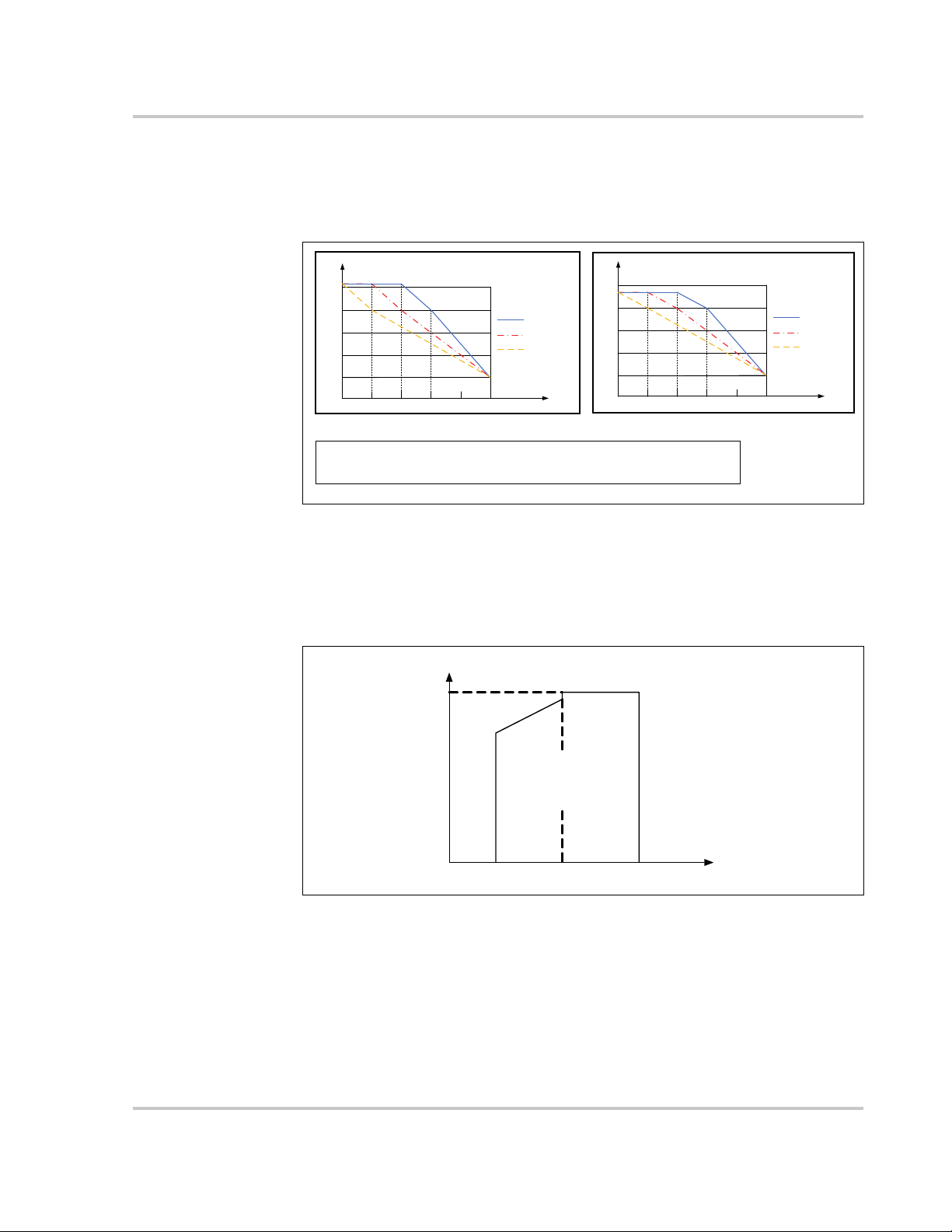
not to scale
V
min
V
max
P
n
215V
Working area
P[Vmin…266V] = Pn × (Vgrid / 230V)
Over-temperature Derating High ambient temperature, a blocked fan, or poor
ventilation will initiate inverter power derating.
When the temperature inside the unit exceeds the upper limit, the inverter will derate
its power output until the internal temperature drops within the allowable range.
Figure 1-9 Over-Temperature Derating
Grid Under-voltage Derating When grid voltage is low, the inverter will derate
the output power to make sure the output current is within the allowable range.
Once the grid voltage is within Vmin (215V), the inverter will derate its output
power.
Figure 1-10 Grid Under-Voltage Derating
975-0768-01-01 Revision B 1–11
Introduction
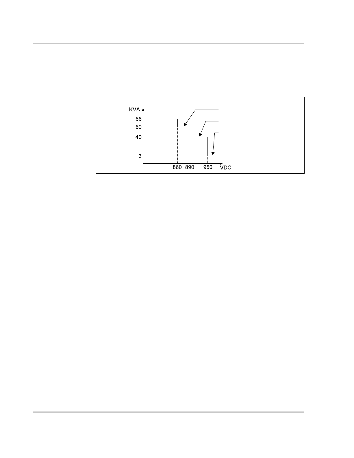
Output voltage max when PV voltage < 860
Output voltage max when PV voltage < 890
Output voltage max when PV voltage < 950
PV Over-voltage Derating The inverter regularly scans the PV voltage every 25
minutes and forces the PV to derate to test whether the maximum power point is
less than 860 volts.
At 66 KVA, if the maximum power point is higher than 860 volts, then the inverter
will return to the higher voltage limit before it starts derating.
Figure 1-11 PV Over-Voltage Derating
1–12 975-0768-01-01 Revision B

2 Installation
Chapter 2 contains information about:
• Pre-Installation
• Installation
975-0768-01-01 Revision B 2–1

Installation
Pre-Installation
Before installing the Conext CL-60, read all instructions and cautionary markings
in this Guide.
NOTE: Obtain all necessary permits prior to starting the installation.
Installations must meet all local codes and standards. Installation of this
equipment should only be performed by skilled personnel such as qualified
electricians and Certified Renewable Energy (RE) System installers.
Planning the Installation
• Read this entire chapter before beginning the installation. It is important to
plan the installation from beginning to end.
• Assemble all tools and materials needed for the installation.
2–2 975-0768-01-01 Revision B
 Loading...