

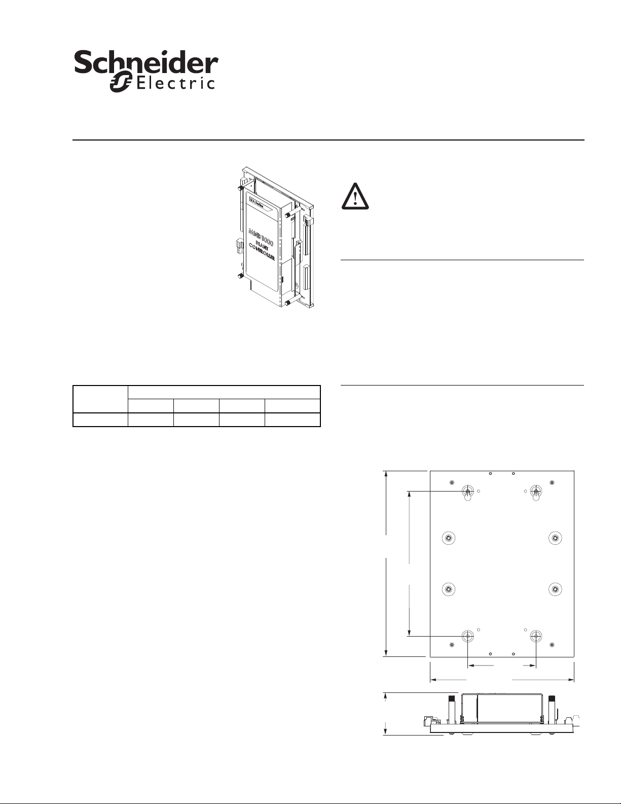
MNB-1000
2-5/16
(58)
Dimensions shown
are in inches (mm).
10-15/16
(278)
8-1/2
(216)
8-3/8 (213)
4 (102)
Figure-1 MNB-1000 Mounting Dimensions.
TAC I/A Series MicroNet BACnet
Plant Controller
Installation Instructions
MicroNetApplication
The TAC I/A Series™ MicroNet™
BACnet™ Plant Controller is an
interoperable controller with native
BACnet, IP, and MS/TP
communications support. The
controller features Sensor Link
(S-Link) support, LED status and
output indication, two Ethernet ports,
and screw terminal blocks.
The Plant Controller’s sequence of
operation and BACnet image are fully
programmable using WorkPlace
Tech Tool, and can be applied to a wide range of mechanical
equipment. Typical applications include central station air
handlers, VAV air handlers, and cooling towers.
Model Chart
Model
MNB-1000 12 4 8 8
UI DI UO DO (Triacs)
Inputs and Outputs
Installation
Precautions
When installing the MNB-1000 controller, be sure to
follow the guidelines outlined in "Precautions" on
page 4.
Location
The MNB-1000 controller is suitable for indoor use only.
Caution:
• Avoid locations where excessive moisture, corrosive
fumes, vibration, or explosive vapors are present.
• Avoid electrical noise interference. Do not install near
large contactors, electrical machinery, or welding
equipment.
• Locate where ambient temperatures do not exceed
140 °F (60 °C) or fall below -40 °F (-40 °C) and relative
humidity does not exceed 85% or fall below 5%,
non-condensing.
Dimensions
Mounting dimensions for the MNB-1000 controller are shown
in Figure-1. Refer to Figure-3 for mounting dimensions for
optional enclosure MNB-1000-ENC.
Inspection
Inspect carton for damage. If damaged, notify carrier
immediately. Inspect controllers for damage upon receipt.
Requirements
• Installer must be a qualified technician
The following items are not provided.
• Job wiring diagrams
• Tools:
– Drill and bits for mounting screws
– Screw drivers
– Nut drivers
– Digital Volt-ohm meter (DVM)
– Static protection wrist strap
• MNB-1000-ENC enclosure for wall-mounting (optional)
• Class 2 power transformer supplying a nominal 50 VA at
24 Vac plus DO load; in European Community,
transformer must conform to EN 60742
• Four #10 pan head screws for wall-mounting
• Four #10 pan head screws for panel-mounting
• If needed, end-of-line termination resistor, 120 Ω ±5%,
part number 40-1758
08-13 © 2013 Schneider Electric. All rights reserved. F-27347-4
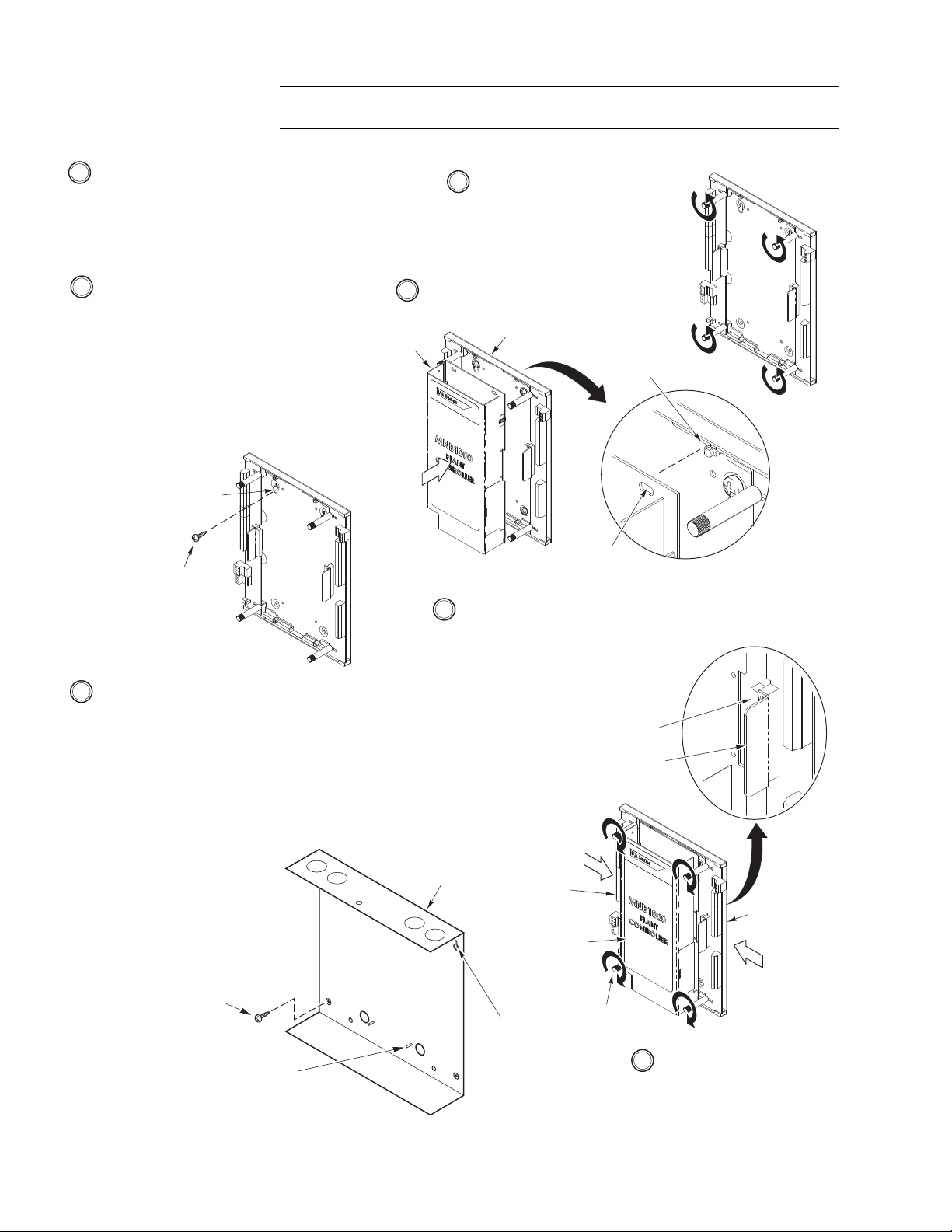
Mounting Mount the controller to the wall according to Figure-2.
7 Tighten the four thumb screws
CW to secure the input and
output boards in place.
5 Position the controller onto
the base plate.
2 To mount the MNB-1000 to a panel, proceed as
follows:
a. Holding the controller's base plate in position,
mark the locations of the four mounting holes
on the panel.
b. Set the base plate aside and drill the marked
mounting holes, using a drill bit sized to the
mounting screws.
c. Secure the base plate to the panel, using four
#10 screws (not supplied).
d.
Continue at Step 4.
3 Optional To mount the MNB-1000 inside Enclosure MNB-1000-ENC,
proceed as follows:
a.
Separate the enclosure cover from the enclosure base.
b. Holding the enclosure's base in position on the wall, mark the
locations of the four mounting holes.
c. Set the enclosure base aside and drill the marked mounting holes,
using a drill bit sized to the mounting screws.
d. Secure the enclosure base to the wall, using four #10 screws (not
supplied).
e. Mount the controller's base
plate onto the four threaded
studs on the enclosure's base.
Secure the base plate, using
four #6-32 nuts (provided).
f.
Continue at Step 4.
Mounting Hole
(1 of 4)
#10 Pan Head
Screw (1 of 4)
(not supplied)
Output
Board
Controller
Input
Board
Thumb Screws
(1 of 4)
Base of Optional
Enclosure
MNB-1000-ENC
Threaded Studs for
Mounting Controller
(1 of 4)
(part of enclosure base)
Mounting
Hole
(1 of 4)
#10 Pan Head
Screw (1 of 4)
(not supplied)
Aluminum
Tab (1 of 2)
Connectors
Controller
Base Plate
Locator Pin
(1 of 4)
Slot
(1 of 4)
1 Select a mounting location. The MNB-1000 may be
panel-mounted or, optionally, enclosure-mounted. To
panel-mount the MNB-1000, go to Step 2. To mount the
MNB-1000 inside optional Enclosure MNB-1000-ENC,
go to Step 3.
Note: The MNB-1000 may be mounted in any
orientation.
4 Be sure the input and output boards
are spread apart as far as possible.
If needed, loosen the four thumb
screws by turning them CCW and
then reposition the boards.
6 Press on the aluminum tabs to slide the input and output boards
into the controller, making sure the mating connectors engage fully.
Note: The connectors are properly
engaged when the gap between
the controller and the input and
output boards is even and minimal
from top to bottom.
Warning: Electrical shock hazard! Disconnect power before installing or removing the
cover.
2 © 2013 Schneider Electric. All rights reserved. F-27347-4
Figure-2 MNB-1000 Mounting.

Enclosure Optionally, the MNB-1000 may be mounted inside an enclosure. Refer to Figure-3 for
11-1/4
(286)
9
(229)
12 (305)
10 (254) 2-5/8 (67)
1
1
1
1 Outside dimensions of the enclosure cover.
Dimensions shown
are in inches (mm).
Enclosure
Cover
Enclosure
Base
I
/
A
Series
®
Figure-3 Enclosure MNB-1000-ENC Mounting Dimensions.
mounting dimensions for enclosure MNB-1000-ENC.
Controller Addressing
DIP Switch
Each MicroNet BACnet controller is equipped with a DIP switch for setting the controller’s
MS/TP network address. Once the address is set, the network is properly wired, and all
routers are configured, WorkPlace Tech Tool (must be version 5.0 or greater) and other
Schneider Electric tools will be able to “see” and work with all the networked BACnet
devices. For guidance in assigning a DIP switch setting that will optimize system
performance, refer to the WorkPlace Tech Tool BACnet Engineering Guide Supplement,
F-27356.
Other BACnet Devices
The UNC and other BACnet devices on the network can work with the MicroNet BACnet
controller once they are assigned unique identifiers and names. MicroNet BACnet
controllers are configured in this way through the Commissioning Tool.
Note: The logical addressing of devices (i.e. the assignment of unique identifiers and
names) is not a prerequisite for using Schneider Electric network management tools. It is,
however, a prerequisite for using the UNC and third-party BACnet devices with MicroNet
BACnet controllers.
EOL Termination
The MNB-1000 is equipped with a jumper-selectable end-of-line (EOL) termination resistor.
The default position for the EOL jumper is “EOL termination not present.” If the controller is
at the end-of-line, set termination according to the MicroNet BACnet Wiring, Networking,
and Best Practices Guide, F-27360.
Note: If another device is at the end-of-line on the MS/TP trunk, use an end-of-line
termination resistor, 120 Ω ±5%, part number 40-1758.
Network Bias Resistors
The MNB-1000 is equipped with two internal, jumper-selectable, network bias resistors for
the MS/TP trunk. The default position for these jumpers is “disabled.” For more information
on these resistors, refer to the MicroNet BACnet Wiring, Networking, and Best Practices
Guide, F-27360.
F-27347-4 © 2013 Schneider Electric. All rights reserved. 3

Installation Completion
Precautions
Finish installing the MNB-1000 controller by performing the wiring and network configuration
tasks outlined in the MicroNet BACnet Wiring, Networking, and Best Practices Guide,
F-27360. Information covered in this Guide include:
• Communications wiring • Logical addressing of devices
– MicroNet BACnet wiring
– Sensor Link (S-Link) wiring
• Configuration of routers
• Communications hardware checkout
• Input/Output wiring • Troubleshooting
• Power supply wiring • A list of related documentation
• Mechanical hardware checkout
General
Warning: Electrical shock hazard! Disconnect power before installing or removing the
cover.
• Follow Static Precautions (below) when installing this equipment.
• Use copper conductors that are suitable for 167°F (75°C).
• Make all connections according to electrical wiring diagram, national and local electrical
codes.
Static Precautions
Static charges damage electronic components. The microprocessor and associated circuitry
are extremely sensitive to static discharge. Use the following precautions when installing,
servicing, or operating the system.
• Work in a static-free area.
• Discharge static electricity by touching a known, securely grounded object.
• Use a wrist strap connected to earth ground when handling the controller’s printed
circuit board.
Federal Communications Commission (FCC)
This equipment has been tested and found to comply with the limits for a Class A digital
device, pursuant to Part 15 of the FCC Rules. These limits are designed to provide
reasonable protection against harmful interference when the equipment is operated in a
commercial environment. This equipment generates, uses, and can radiate radio frequency
energy, and, if not installed and used in accordance with the instruction manual, may cause
harmful interference to radio communications. Operation of this equipment in a resdential
area is likely to cause harmful interference, in which case the user will be required to correct
the interference at his own expense.
Canadian Department of Communications (DOC)
This Class A digital apparatus meets all requirements of the Canadian Interference-Causing
Equipment Regulations.
European Community Directives
This equipment meets all requirements of European Community Directives for Low Voltage
(72/23/EEC), General Safety (92/59/EEC), and Electromagnetic Compatibility
(89/336/EEC).
Distributed, manufactured, and sold by Schneider Electric. I/A Series trademarks are owned by Invensys Systems, Inc. and are used on this product under master
license from Invensys. Invensys does not manufacture this product or provide any product warranty or support. For service, support, and warranty information, contact
Schneider Electric at 1-888-444-1311.
All brand names, trademarks and registered trademarks are the property of their respective owners. Information contained within this document is subject to change without notice.
Schneider Electric
F-27347-4 August 2013 ptm
© 2013 Schneider Electric. All rights reserved.
 Loading...