


Schneider Electric MNL-10Rxx Series, MNL-15Rxx Series, MNL-20Rxx Series Installation Instructions
Applicable Documentation
F-Number |
Description |
|
Audience |
Purpose |
|
|
TAC I/A Series MicroNet |
– |
Application Engineers |
Provides step-by-step installation and checkout procedures for TAC |
|
|
– |
Installers |
|||
F-26277 |
MN-Sx Series Sensors |
I/A Series MicroNet MN-Sx Series Sensors. Also contains |
|||
– |
Service Personnel |
||||
|
General Instructions |
instructions for sensor operation. |
|||
|
– |
Start-up Technicians |
|||
|
|
|
|||
|
|
|
|
|
|
|
|
– |
Application engineers |
Provides an overview of the TAC I/A Series MicroNet System. It |
|
F-26303 |
TAC I/A Series MicroNet |
– |
Installers |
includes brief descriptions of the hardware and software components, |
|
System Overview |
– |
Start-up technicians |
and how they may be combined to create MicroNet networks and |
||
|
|||||
|
|
– |
Service personnel |
stand-alone systems. |
|
|
|
|
|
|
|
|
|
– |
Application Engineers |
|
|
F-27254 |
WorkPlace Tech Tool 4.0 |
– |
Installers |
Provides engineering and technical information for applying and |
|
Engineering Guide |
– |
Service Personnel |
using all aspects of WorkPlace Tech Tool. |
||
|
|||||
|
|
– |
Start-up Technicians |
|
|
|
|
|
|
|
|
|
TAC I/A Series MicroNet |
– |
Application Engineers |
Provides engineering and technical information to assist in |
|
|
– |
Installers |
|||
F-26507 |
Systems Engineering |
designing a complete MicroNet controller system using different |
|||
– |
Service Personnel |
||||
|
Guide |
architectures, components, and software. |
|||
|
– |
Start-up Technicians |
|||
|
|
|
|||
|
|
|
|
|
|
|
|
– |
Application Engineers |
|
|
F-27255 |
WorkPlace Tech Tool 4.0 |
– |
Installers |
Provides step-by-step instructions for using WorkPlace Tech Tool. |
|
User’s Guide |
– |
Service Personnel |
|||
|
|
||||
|
|
– |
Start-up Technicians |
|
|
|
|
|
|
|
|
|
EN-206 Guidelines for |
|
|
Offers guidelines for avoiding equipment damage associated with |
|
|
Powering Multiple Full- |
– |
Application Engineers |
improperly wiring devices of varying rectifier types. Contains |
|
F-26363 |
Wave and Half-Wave |
– |
Installers |
instructions for identifying device rectifier type, guidelines for |
|
|
Rectifier Devices from a |
– |
Service Personnel |
correctly powering devices of varying rectifier types, and examples |
|
|
Common Transformer |
|
|
illustrating proper power wiring techniques. |
|
|
|
|
|
|
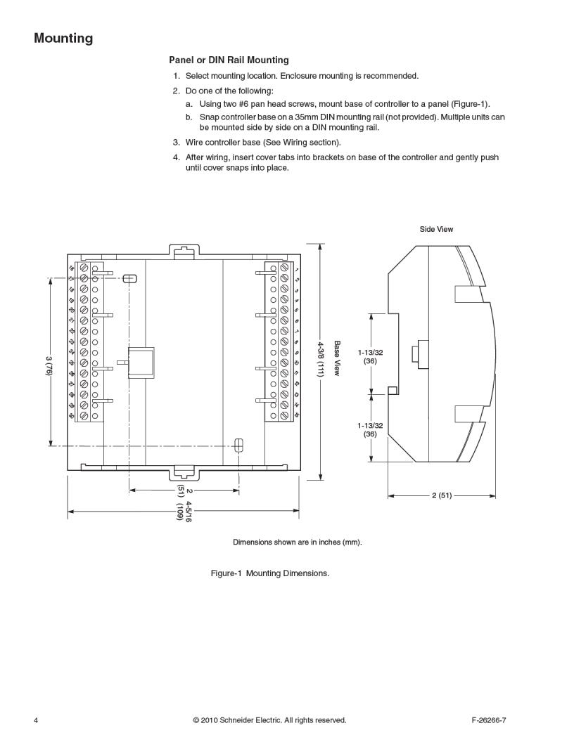
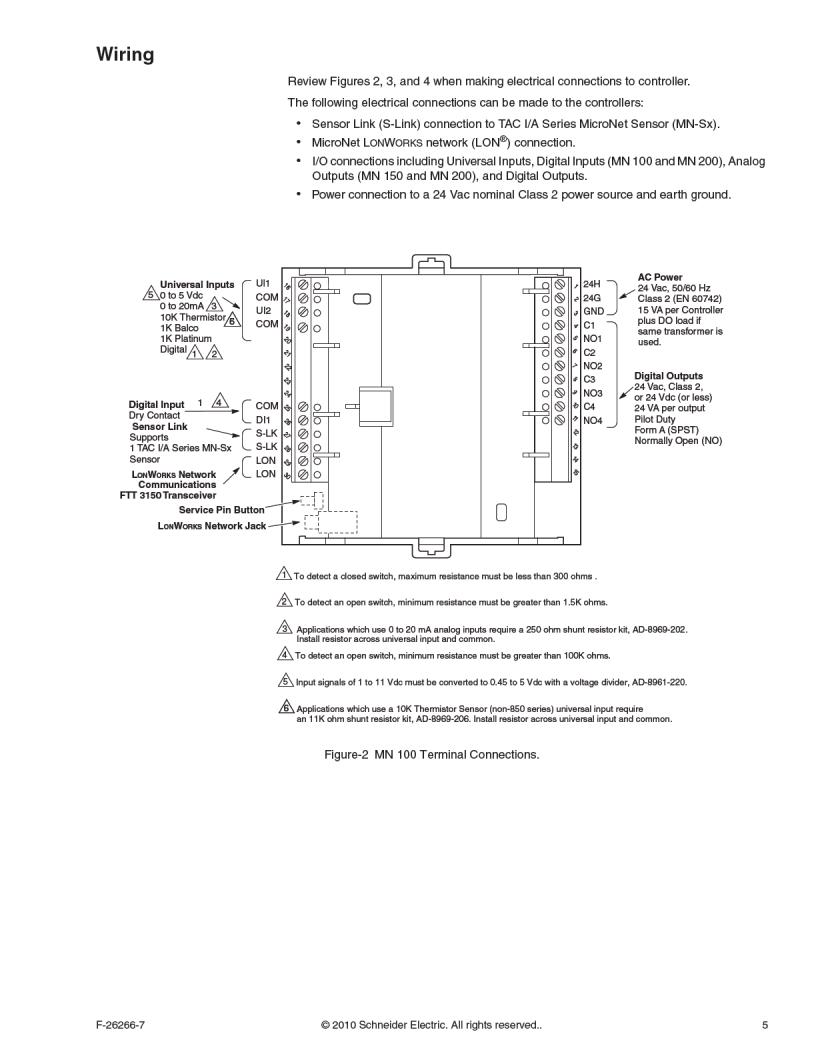
Installation
Inspection |
Inspect carton for damage. If damaged, notify carrier immediately. Inspect controllers for |
|
|
damage upon receipt. |
|
Requirements |
• |
Installer must be a qualified, experienced technician. |
(These items not provided) |
• |
Job wiring diagrams |
|
• |
Tools: |
|
|
– Drill and bits for panel mounting screws |
|
|
– Digital Volt-ohm meter (DVM) |
|
|
– Static protection wrist strap |
|
• MNA-FLO-1 enclosure for connecting to conduit (optional) |
|
|
• Class 2 power transformer supplying a nominal 24 Vac (20.4 to 30 Vac) with a minimum |
|
|
|
rating of 15 Va, 50/60 Hz per controller plus Digital Output (DO) loads (if same |
|
|
transformer is used). In European Community, transformer must conform to EN 60742 |
|
• |
Terminators: |
– One LON-TERM1 terminator required for each free topology segment
– Two LON-TERM2 terminators required for each bus topology segment
• Two #6 pan head panel mounting screws or 35mm DIN rail for mounting
2 |
© 2010 Schneider Electric. All rights reserved. |
F-26266-7 |

 Loading...