


Schneider Electric MGE 5500 User Manual
Operation
MGEGalaxy5500
40-130kVA480Vand20–120kVA400V


TableofContents
AboutThisManual.........................................................................................................1
SymbolsUsed...............................................................................................................1
CompanionManuals...................................................................................................1
FindUpdatestothisManual.....................................................................................1
Overview..............................................................................................................................2
ProductFeatures..........................................................................................................2
UserInterface................................................................................................................3
DisplayScreens............................................................................................................4
BasicOperationofDisplay........................................................................................4
Measurements...........................................................................................................5
Alarms.......................................................................................................................5
Status........................................................................................................................5
Settings.....................................................................................................................6
Controls.....................................................................................................................6
UPSConguration.........................................................................................................7
AccesstothePersonalizationFunctions..............................................................7
PersonalizationSettings............................................................................................7
Operation............................................................................................................................9
OperatingModes..........................................................................................................9
Normal(DoubleConversion)Mode............................................................................9
ECOMode(SingleUPSOnly)....................................................................................9
FrequencyConverter.................................................................................................10
LoadonBatteryPower..............................................................................................10
OperationofMimic-PanelLEDs...............................................................................11
OperationProcedures................................................................................................12
ShutDownaSingleUPS............................................................................................12
RestartaSingleUPS..................................................................................................13
ShutDownaParallelConguration...........................................................................14
RestartaParallelConguration.................................................................................14
OperationoftheRelayCommunicationCard(DryContacts)...............16
StandardMode..............................................................................................................16
ProgrammableMode...................................................................................................17
990-5219A-001
MGEGalaxy550040-130kV A480Vand20–120kV A400VOperation
i

ListofOperatingStatusConditionsThatCanbeAssignedtoanSECI
Output.............................................................................................................................17
Maintenance......................................................................................................................20
LifeCycleMonitoring(LCM).....................................................................................20
ServicingBatteries......................................................................................................21
IMPORTANTSAFETYINSTRUCTIONSFORSERVICINGBATTERIES........................21
UPSIsolation.................................................................................................................22
IsolateSingleUPS.....................................................................................................22
IsolateUPSfunctioningasFrequencyConverter(ONLYMGEGalaxy5500400
V)...............................................................................................................................23
IsolateUPSoperatinginECOmode..........................................................................23
IsolateParallelUPSWithoutExternalBypassCabinet..............................................24
IsolateParallelUPSWithExternalBypassCabinet...................................................25
ReturntoNormalOperation......................................................................................28
ReturntoNormalOperation,SingleUPS...................................................................28
ReturntoNormalOperation,FrequencyConverter(ONLYMGEGalaxy5500400
V)...............................................................................................................................29
ReturntoNormalOperation,ParallelUPSWithoutExternalBypassCabinet............29
ReturntoNormalOperation,ParallelUPSwithExternalBypassCabinet..................32
Troubleshooting..............................................................................................................34
IdenticationofAlarms..............................................................................................34
AlarmorStatusDisplayMessagesList.................................................................35
ii
MGEGalaxy550040-130kV A480Vand20–120kV A400VOperation
990-5219A-001

AboutThisManual
Thismanualdescribesthestartup,shutdown,andnormaloperationoftheMGEGalaxy5500with
informationontheuserinterfacedisplayanddisplaymenustructure.Formaintenancethemanual
describesalarmconditions,UPSisolationoperationandmaintenanceandsafetyinformationonservicing
batteriesfortheMGEGalaxy5500.
SymbolsUsed
WARNING:Indicatesanelectricalhazard,which,ifnotavoided,couldresultininjury
ordeath.
Caution:Indicatesahazard,which,ifnotavoided,couldresultininjuryordeath.
Note:Indicatesimportantinformation.
See:Indicatesthatmoreinformationisavailableonthesubject.
CompanionManuals
ForadditionalinformationabouttheMGEGalaxy5500,seethefollowingdocuments:
•MGEGalaxy5500Installation–990–5217–001
•MGEGalaxy5500Receiving&Unpacking–990–5218–001
•NetworkManagementCardInstallationManual990–3194–001
FindUpdatestothisManual
Youcancheckforupdatestothismanualonwww.apc.com.Lookforthelatestletterrevision(A,
Betc.)ofthemanual.
990-5219A-001
MGEGalaxy550040-130kV A480Vand20–120kV A400VOperation
1

Overview
ProductFeatures
Features
DisplayScreens
Measurements
Alarms
Status
Settings
Controls
OperatingModes
NormalMode
ECOMode
FrequencyConverter
Mode
RelayCommunicationCard
DryContacts
Maintenance
LifeCycleMonitoring
ServicingBatteries
MGEGalaxy5500
20–120kVA400V
MGEGalaxy5500
40–130kVA480V
Refertosection
“Measurements“
“Alarms“
“Status“
“Settings“
“Controls“
“OperatingModes“
“OperatingModes“
“OperatingModes“
“OperationoftheRelay
CommunicationCard
(DryContacts)“
“LifeCycleMonitoring
(LCM)“
“ServicingBatteries“
2
MGEGalaxy550040-130kV A480Vand20–120kV A400VOperation
990-5219A-001
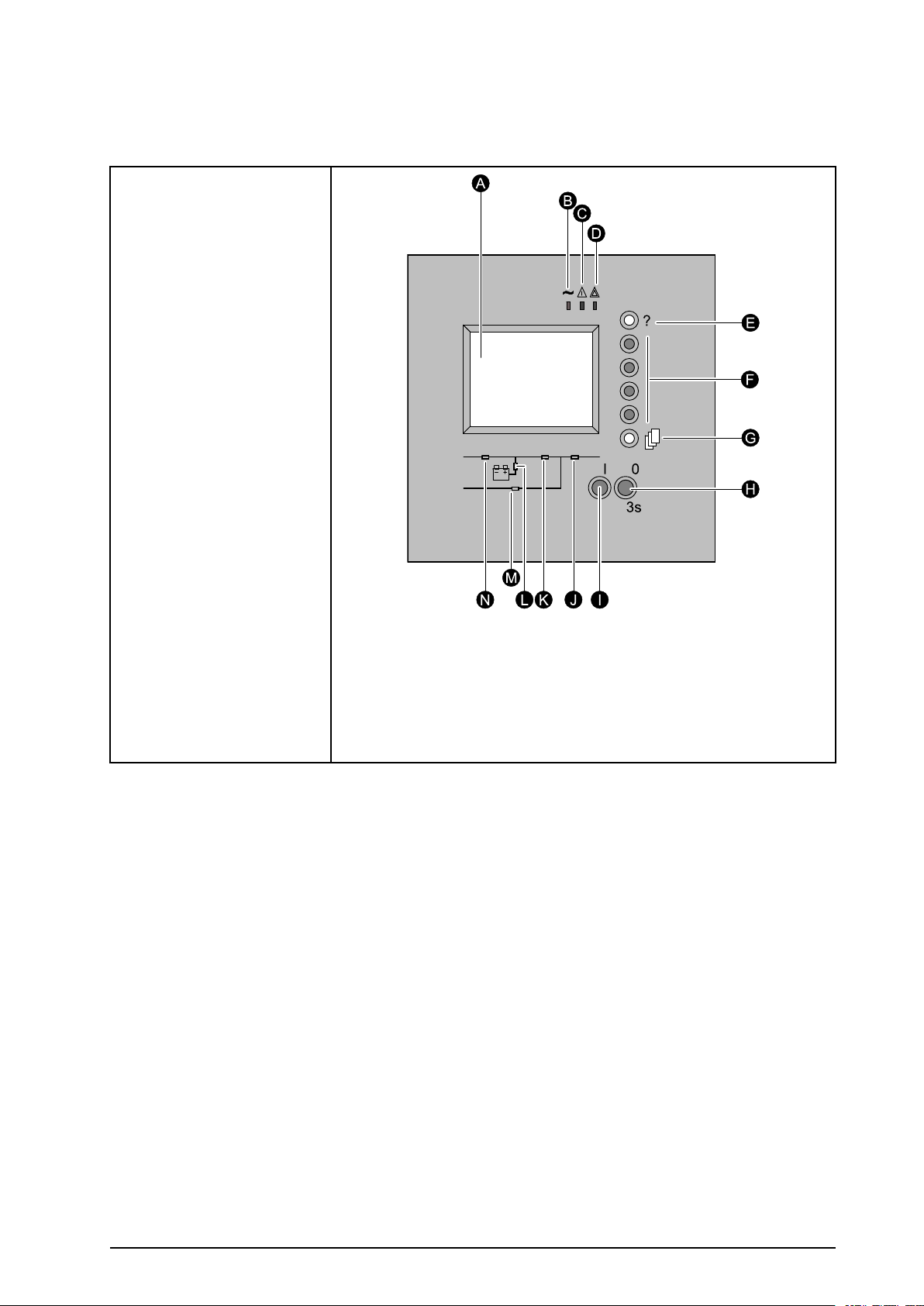
UserInterface
TheUPSisoperatedusingthecontrolanddisplayinterface.
A.GraphicalDisplay
B.LoadprotectedLED
C.MinorfaultLED
D.MajorfaultLED
E.Helpkey
F.Functionkeys.Each
keycorrespondsto
afunctionpresented
onthedisplay .The
functionofeachkey
changesdependingon
themenudisplayedon
thescreen.
G.Menukey .Thisbutton
providesdirectaccess
tothemainmenu.
H.OFFbutton.
I.ONbutton.
J.LoadsuppliedLED
K.UPSONLED
L.Operationonbattery
powerLED
M.Bypassinoperation
LED
N.PFCONLED
990-5219A-001
MGEGalaxy550040-130kV A480Vand20–120kV A400VOperation
3

DisplayScreens
BasicOperationofDisplay
4
MGEGalaxy550040-130kV A480Vand20–120kV A400VOperation
990-5219A-001

Measurements
TheMeasurementsdisplayscreensconsistofthefollowingmeasurementsscreens:
1.PresstheMenukeytoreturntotheMainMenu.
2.Usethefunctionkeys↑or↓tohighlightMeasurementsonthedisplay.
3.Pressthefunctionkey←toselectMeasurements.
4.Usethefunctionkeys↑or↓toselectbetweenthefollowingmeasurements:
•BatteryMeasurements
•V oltageMeasurements
•CurrentMeasurements
•PowerMeasurements
•FrequencyMeasurements
•RatiosMeasurements
•ParallelMeasurements(option)
5.Pressthefunctionkey←toselecttherequiredmeasurementsscreen.
Alarms
Detailedinformationonallalarmsissuppliedonthedisplay.Seethe“AlarmorStatusDisplayMessages
List“undertheTroubleshootingsectionforalistofpossiblealarmmessagesinthedisplay.
1.PresstheMenukeytoreturntotheMainMenu.
2.Usethefunctionkeys↑or↓tohighlightAlarmsonthedisplay.
3.Pressthefunctionkey←toselectAlarms.
4.Usethefunctionkeys↑or↓toselectbetweenthealarmmessages.
5.Pressthefunctionkey←toselecttherequiredalarmscreen.
Status
TheStatusdisplayscreensconsistofthefollowingStatusscreens:
1.PresstheMenukeytoreturntotheMainMenu.
2.Usethefunctionkeys↑or↓tohighlightStatusonthedisplay.
3.Pressthefunctionkey←toselectStatus.
4.Usethefunctionkeys↑or↓toselectbetweenthefollowingtwoStatusscreens:
•Timestampedevents
•Statistics
5.Pressthefunctionkey←toselecttherequiredStatusscreen.
990-5219A-001
MGEGalaxy550040-130kV A480Vand20–120kV A400VOperation
5

Settings
TheSettingsdisplayscreensconsistofthefollowingSettingsscreens:
1.PresstheMenukeytoreturntotheMainMenu.
2.Usethefunctionkeys↑or↓tohighlightSettingsonthedisplay.
3.Pressthefunctionkey←toselectSettings.
4.Usethefunctionkeys↑or↓toselectbetweentheSettingsscreens:
•Language
•Date/time
•Displaycontrast
•Buzzervolume
•Personalization
•Outputvoltage
•Password
•Dry-contactsettings
5.Pressthefunctionkey←toselecttherequiredSettingsscreen.
Controls
TheControlsdisplayscreensconsistofthefollowingControlsscreens:
1.PresstheMenukeytoreturntotheMainMenu.
2.Usethefunctionkeys↑or↓tohighlightControlsonthedisplay.
3.Pressthefunctionkey←toselectControls.
4.Usethefunctionkeys↑or↓toselectbetweentheControlsscreens:
•ResetAlarms
•Inverteron
•Inverteroff
•Forceloadtransfertoinverter
•Forceloadtransfertobypass
•Desynchronizeinverterfrombypass
•Resynchronizeinverterandbypass
•TestsLEDs
•BuzzerOFF
•EnableLCMindications
•DisableLCMindications
5.Pressthefunctionkey←toselecttherequiredControlsscreen.
6
MGEGalaxy550040-130kV A480Vand20–120kV A400VOperation
990-5219A-001

UPSConguration
AccesstothePersonalizationFunctions
Caution:PersonalizationmustbecarriedoutwithswitchesQ1andQ5Nopen(OFF)and
switchQ4SandQ3BPclosed(ON).
1.Pressthemenukey(A).
2.SelectSettings,thenPersonalizationusingthe
functionkeys(B)↑or↓.
3.Conrmbypressingthefunctionkey(B)←.
4.Enterthepasswordbysuccessivelyselecting
eachiconusingthecorrespondingfunctionkey.
5.Conrmbypressingthefunctionkey(B)←.
6.Tosavethepersonalizationsettings,conrmby
pressingthefunctionkey(B)←.
Thepasswordisfactorysetto:
Forinformationonhowtochangethepassword,
seeSettingsunder“DisplayScreens“.
PersonalizationSettings
OperatingMode
FunctionFactorysettingOptions
UPSoperatingmode
UPSautomaticstartDisabledEnabled
Authorizednumberofstarts
Delaybeforeresetofnumberof
executedautomaticstarts
Frequency
FunctionFactorysettingOptions
UPSoutputfrequency
ToleranceforbypassACsource
Synchronizationspeedwithbypass
ACsource
NORMALECO
41to255
4seconds1to60seconds
For480V:60Hz
For400V:50Hz
8%0.5–1–2–4%
2Hz/s1Hz/s
60Hz
990-5219A-001
MGEGalaxy550040-130kV A480Vand20–120kV A400VOperation
7

AutomaticBypass
FunctionFactorysettingOptions
TransfertobypassACsourceEnabledDisabled–disabledwhenlimiting
TransfertobypasswithbypassAC
sourceoutoftolerances
EnabledDisabled
Battery
FunctionFactorysettingOptions
Lowbatterywarningthresholdif
batterymonitorinactive
Lowbatterywarningthresholdif
batterymonitoractive
Intervalbetweentwobatterytests30days1to180days
40%ofremainingbackuptime20–60–80%ofremainingbackup
time
4minutesofbatterybackuptime1toXminutesofbatterybackup
time
8
MGEGalaxy550040-130kV A480Vand20–120kV A400VOperation
990-5219A-001

Operation
Caution:Alloperationsconcerningsystemstart-upandcompliancewithstandardsand
regulations,includingthoserelatedtothebatterycabinet,mustbecarriedoutbytrainedand
certiedpersonnelbeforeusingtheUPS.
OperatingModes
Normal(DoubleConversion)Mode
Thisisthestandardoperatingmode,setbydefaultinthefactory.T wopossiblecases:
1.NormalACsourceavailable:LED(A)isON.
TheloadisprotectedbytheUPS.
2.NormalACsourcenotavailable:LED(B)isON.
Thebuzzersoundsintermittently .Operationonbattery
powerLEDonthemimic-panelisgreen.
TheloadissuppliedbytheUPSfrombatterypower.
Note:ThedisplayindicatesanyanomaliesrelatedtotheACsourceortheUPSaswell
asremedialactionifapplicable.Pressthefunctionkeyindicatedbythedisplaytoturn
thebuzzerOFF.
ECOMode(SingleUPSOnly)
Themainadvantageofthismodeisthatitreducestheconsumptionofelectricalpower.ECOmodemaybe
selectedexclusivelyviathecontrolpanelontheUPS.Threepossiblescenarios:
1.BypassACsourceavailable:LED(A)isON.
TheloadissuppliedinECOmode.
2.BypassACsourcenotavailable:LED(A)isON.The
buzzersoundsintermittently.Theloadisautomatically
suppliedinnormalmodeviatheNormalACinput.
990-5219A-001
MGEGalaxy550040-130kV A480Vand20–120kV A400VOperation
9
 Loading...