


Schneider Electric ACRD601, ACRD602, ACRD602P, ACRD600P, ACRD601P User Manual
...
Installation Manual
InRow® Direct Expansion Air Conditioners
InRow RD DX
ACRD600, ACRD601, ACRD602,
ACRD600P, ACRD601P, ACRD602P
990-5711C-001
Publication Date: April 2017

Schneider Electric IT Corporation Legal Disclaimer
The information presented in this manual is not warranted by the Schneider Electric IT Corporation to be
authoritative, error free, or complete. This publication is not meant to be a substitute for a detailed operational
and site specific development plan. Therefore, Schneider Electric IT Corporation assumes no liability for
damages, violations of codes, improper installation, system failures, or any other problems that could arise
based on the use of this Publication.
The information contained in this Publication is provided as is and has been prepared solely for the purpose of
evaluating data center design and construction. This Publication has been compiled in good faith by Schneider
Electric IT Corporation. However, no representation is made or warranty given, either express or implied, as to
the completeness or accuracy of the information this Publication contains.
IN NO EVENT SHALL SCHNEIDER ELECTRIC IT CORPORATION, OR ANY PARENT, AFFILIATE OR
SUBSIDIARY COMPANY OF SCHNEIDER ELECTRIC IT CORPORATION OR THEIR RESPECTIVE
OFFICERS, DIRECTORS, OR EMPLOYEES BE LIABLE FOR ANY DIRECT, INDIRECT, CONSEQUENTIAL,
PUNITIVE, SPECIAL, OR INCIDENTAL DAMAGES (INCLUDING, WITHOUT LIMITATION, DAMAGES FOR
LOSS OF BUSINESS, CONTRACT, REVENUE, DATA, INFORMATION, OR BUSINESS INTERRUPTION)
RESULTING FROM, ARISING OUT, OR IN CONNECTION WITH THE USE OF, OR INABILITY TO USE THIS
PUBLICATION OR THE CONTENT, EVEN IF SCHNEIDER ELECTRIC IT CORPORATION HAS BEEN
EXPRESSLY ADVISED OF THE POSSIBILITY OF SUCH DAMAGES. SCHNEIDER ELECTRIC IT
CORPORATION RESERVES THE RIGHT TO MAKE CHANGES OR UPDATES WITH RESPECT TO OR IN
THE CONTENT OF THE PUBLICATION OR THE FORMAT THEREOF AT ANY TIME WITHOUT NOTICE.
Copyright, intellectual, and all other proprietary rights in the content (including but not limited to software, audio,
video, text, and photographs) rests with Schneider Electric IT Corporation or its licensors. All rights in the
content not expressly granted herein are reserved. No rights of any kind are licensed or assigned or shall
otherwise pass to persons accessing this information.
This Publication shall not be for resale in whole or in part.

Table of Contents
Safety.................................................................................1
Important Safety Information . . . . . . . . . . . . . . . . . . . . . . . . . . . . . . . . . 1
Safety Considerations While Installing This Equipment . . . . . . . . . . . . . 2
General Information...........................................................3
Overview. . . . . . . . . . . . . . . . . . . . . . . . . . . . . . . . . . . . . . . . . . . . . . . . . 3
Save these instructions . . . . . . . . . . . . . . . . . . . . . . . . . . . . . . . 3
Symbols used in this manual . . . . . . . . . . . . . . . . . . . . . . . . . . 3
Equipment Disposal . . . . . . . . . . . . . . . . . . . . . . . . . . . . . . . . . . . . . . . . 3
Waste Electrical and Electronic Equipment (WEEE) disposal . 3
Inspecting the Equipment . . . . . . . . . . . . . . . . . . . . . . . . . . . . . . . . . . . . 3
Filing a claim . . . . . . . . . . . . . . . . . . . . . . . . . . . . . . . . . . . . . . . 3
Storing the Equipment Before Installation . . . . . . . . . . . . . . . . . . . . . . . 3
Moving the Equipment . . . . . . . . . . . . . . . . . . . . . . . . . . . . . . . . . . . . . . 4
Model Identification. . . . . . . . . . . . . . . . . . . . . . . . . . . . . . . . . . . . . . . . . 4
Standard unit . . . . . . . . . . . . . . . . . . . . . . . . . . . . . . . . . . . . . . . 4
Component Identification . . . . . . . . . . . . . . . . . . . . . . . . . . . . . . . . . . . . 5
Install kit inventory . . . . . . . . . . . . . . . . . . . . . . . . . . . . . . . . . . . 5
Exterior components . . . . . . . . . . . . . . . . . . . . . . . . . . . . . . . . . 6
Interior components (ACRD60x) . . . . . . . . . . . . . . . . . . . . . . . . 7
Interior components (ACRD60xP) . . . . . . . . . . . . . . . . . . . . . . . 9
Electrical panel . . . . . . . . . . . . . . . . . . . . . . . . . . . . . . . . . . . . 11
Refrigeration piping diagram . . . . . . . . . . . . . . . . . . . . . . . . . . 13
Connections overview . . . . . . . . . . . . . . . . . . . . . . . . . . . . . . . 14
Power connections . . . . . . . . . . . . . . . . . . . . . . . . . . . . . . . . . 14
Piping connections . . . . . . . . . . . . . . . . . . . . . . . . . . . . . . . . . 14
Communication connections . . . . . . . . . . . . . . . . . . . . . . . . . . 15
Room Preparation . . . . . . . . . . . . . . . . . . . . . . . . . . . . . . . . . . . . . . . . 16
Air distribution . . . . . . . . . . . . . . . . . . . . . . . . . . . . . . . . . . . . . 16
Incoming power supply requirement . . . . . . . . . . . . . . . . . . . . 16
Service access . . . . . . . . . . . . . . . . . . . . . . . . . . . . . . . . . . . . 17
Weights and Dimensions . . . . . . . . . . . . . . . . . . . . . . . . . . . . . . . . . . . 18
InRow RD Installation Manual i

Access Locations . . . . . . . . . . . . . . . . . . . . . . . . . . . . . . . . . . . . . . . . . 19
Top piping and power access locations—top view, looking down (ACRD600/P series) 19
Bottom piping and power access locations—bottom view, looking up (ACRD600/P series)
20
Equipment Guidelines......................................................21
Working Conditions and Environmental Limits . . . . . . . . . . . . . . . . . . 21
Installation........................................................................22
Removing the Doors and Panels . . . . . . . . . . . . . . . . . . . . . . . . . . . . . 22
Removing the front and rear doors . . . . . . . . . . . . . . . . . . . . . 23
Removing and installing the side panel . . . . . . . . . . . . . . . . . . 24
Removing the electrical panel cover . . . . . . . . . . . . . . . . . . . . 25
Joining the Equipment to Enclosures. . . . . . . . . . . . . . . . . . . . . . . . . . 26
Joining to NetShelter™ SX enclosures . . . . . . . . . . . . . . . . . . 26
Joining to NetShelter VX and VS enclosures . . . . . . . . . . . . . 26
Leveling the Equipment . . . . . . . . . . . . . . . . . . . . . . . . . . . . . . . . . . . . 27
Mechanical Connections . . . . . . . . . . . . . . . . . . . . . . . . . . . . . . . . . . . 28
Refrigeration piping . . . . . . . . . . . . . . . . . . . . . . . . . . . . . . . . . 28
Connect refrigerant lines . . . . . . . . . . . . . . . . . . . . . . . . . . . . . 30
Condenser . . . . . . . . . . . . . . . . . . . . . . . . . . . . . . . . . . . . . . . . 30
Flooded receiver . . . . . . . . . . . . . . . . . . . . . . . . . . . . . . . . . . . 30
Humidifier (ACRD60xP only) . . . . . . . . . . . . . . . . . . . . . . . . . . 31
Condensate pump . . . . . . . . . . . . . . . . . . . . . . . . . . . . . . . . . . 32
Condensate overflow . . . . . . . . . . . . . . . . . . . . . . . . . . . . . . . . 33
Leak sensor (optional) . . . . . . . . . . . . . . . . . . . . . . . . . . . . . . . 34
Adding a holding charge . . . . . . . . . . . . . . . . . . . . . . . . . . . . . 35
Adding compressor oil . . . . . . . . . . . . . . . . . . . . . . . . . . . . . . . 35
Electrical Connections . . . . . . . . . . . . . . . . . . . . . . . . . . . . . . . . . . . . . 36
Customer interface connections . . . . . . . . . . . . . . . . . . . . . . . 37
Form C alarm contacts and shutdown input . . . . . . . . . . . . . . 39
Rack temperature sensors . . . . . . . . . . . . . . . . . . . . . . . . . . . 39
Communication connections . . . . . . . . . . . . . . . . . . . . . . . . . . 41
Network port . . . . . . . . . . . . . . . . . . . . . . . . . . . . . . . . . . . . . . 43
Power Connections . . . . . . . . . . . . . . . . . . . . . . . . . . . . . . . . . . . . . . . 44
Wiring configurations . . . . . . . . . . . . . . . . . . . . . . . . . . . . . . . . 44
Top routing . . . . . . . . . . . . . . . . . . . . . . . . . . . . . . . . . . . . . . . 44
Bottom routing . . . . . . . . . . . . . . . . . . . . . . . . . . . . . . . . . . . . . 45
Strain relief (ACRD602/602P only) . . . . . . . . . . . . . . . . . . . . . 45
Connect flooded receiver heater . . . . . . . . . . . . . . . . . . . . . . . 46
Voltage selections—ACRD60x units . . . . . . . . . . . . . . . . . . . . 46
Voltage selections – ACRD60xP units . . . . . . . . . . . . . . . . . . 47
ii
InRow RD Installation Manual

Charging with Refrigerant. . . . . . . . . . . . . . . . . . . . . . . . . . . . . . . . . . . 48
Calculating R410A charge . . . . . . . . . . . . . . . . . . . . . . . . . . . 48
Charging the equipment . . . . . . . . . . . . . . . . . . . . . . . . . . . . . 48
Compressor Oil Charge . . . . . . . . . . . . . . . . . . . . . . . . . . . . . . . . . . . . 52
Oil charging procedure . . . . . . . . . . . . . . . . . . . . . . . . . . . . . . 52
Accessories .....................................................................54
Low Temperature Kit . . . . . . . . . . . . . . . . . . . . . . . . . . . . . . . . . . . . . . 54
Unpacking . . . . . . . . . . . . . . . . . . . . . . . . . . . . . . . . . . . . . . . . 54
Install kit inventory . . . . . . . . . . . . . . . . . . . . . . . . . . . . . . . . . . 56
Installation . . . . . . . . . . . . . . . . . . . . . . . . . . . . . . . . . . . . . . . . 57
Bulb location . . . . . . . . . . . . . . . . . . . . . . . . . . . . . . . . . . . . . . 61
Heater connection location . . . . . . . . . . . . . . . . . . . . . . . . . . . 62
iiiInRow RD Installation Manual

Safety
Important Safety Information
Read the instructions carefully to become familiar with the equipment before trying to install, operate, service,
or maintain it. The following special messages may appear throughout this manual or on the equipment to warn
of potential hazards or to call attention to information that clarifies or simplifies a procedure.
The addition of this symbol to a Danger or Warning safety label indicates that an electrical hazard
exists which will result in personal injury if the instructions are not followed.
This is the safety alert symbol. It is used to alert you to potential personal injury hazards. Obey all
safety messages that follow this symbol to avoid possible injury or death.
DANGER
DANGER indicates an imminently hazardous situation which, if not avoided, will result in death
or serious injury.
WARNING
WARNING indicates a potentially hazardous situation which, if not avoided, can result in death
or serious injury.
CAUTION
CAUTION indicates a potentially hazardous situation which, if not avoided, can result in minor
or moderate injury.
NOTICE
NOTICE addresses practices not related to physical injury including certain environmental
hazards, potential damage or loss of data.
1InRow RD Installation Manual

Safety Considerations While Installing This Equipment
DANGER
HAZARD OF ELECTRIC SHOCK, EXPLOSION, OR ARC FLASH
• Apply appropriate personal protective equipment (PPE) and follow safe electrical work
practices. See NFPA 70E or CSA Z462.
• This equipment must be installed and serviced by qualified personnel only.
• Turn off all power supplying this equipment before working on or inside the equipment.
• Always use a properly rated voltage sensing device to confirm power is off.
• Replace all devices, doors, and covers before turning on power to this equipment.
Failure to follow these instructions will result in death or serious injury.
WARNING
HAZARD FROM MOVING PARTS
Keep hands, clothing, and jewelry away from moving parts. Check the equipment for
foreign objects before closing the doors and starting the equipment.
Failure to follow these instructions can result in death, serious injury, or
equipment damage.
WARNING
HAZARD TO EQUIPMENT OR PERSONNEL
All work must be performed by Schneider Electric qualified personnel.
Failure to follow these instructions can result in death, serious injury, or
equipment damage.
WARNING
HAZARD OF EQUIPMENT FALLING OVER
• Use two or more persons at all times to move or turn this equipment.
• Always push, pull, or turn while facing the front and rear of this equipment. Never push,
pull, or turn while facing the sides of this equipment.
• Slowly move this equipment across uneven surfaces or door thresholds.
• Lower leveling feet to floor when this equipment is at rest.
• Lower leveling feet and attach joining brackets to adjacent racks when this equipment is
in final position.
Failure to follow these instructions can result in death, serious injury, or
equipment damage.
InRow RD Installation Manual2
General Information
Overview
Save these instructions
This manual contains important instructions that must be followed during the installation of this equipment.
Symbols used in this manual
Indicates that more information is available in another location.
Equipment Disposal
Waste Electrical and Electronic Equipment (WEEE) disposal
Schneider Electric products comply with international directives on the Restriction of
Hazardous Substances (RoHS) in electronic and electrical equipment and the disposal of
Waste Electrical and Electronic Equipment (WEEE). Dispose of any waste electronic or
electrical equipment with the appropriate recycling center. Contact Schneider Electric for
assistance.
Inspecting the Equipment
Your InRow air conditioner has been tested and inspected for quality assurance before shipment from
Schneider Electric. Carefully inspect both the exterior and interior of the equipment immediately upon receipt to
ensure that the equipment has not been damaged during transit.
Verify that all parts ordered were received as specified and that the equipment is the correct type, size, and
voltage.
Filing a claim
If damage is identified on receipt of the equipment, note the damage on the bill of lading and file a damage
claim with the shipping company. Contact Schneider Electric Worldwide Customer Support for information on
how to file a claim with the shipping company. The shipping claim must be filed at the receiving end of the
delivery.
NOTE: In case of shipping damage, do not operate the equipment. Keep all packaging for inspection by the
shipping company and contact Schneider Electric.
Storing the Equipment Before Installation
If the equipment will not be installed immediately, store it in a safe place, protected from the weather.
NOTICE
HAZARD TO EQUIPMENT
Leaving the equipment uncovered and exposed to possible damage from the
environment will void the factory warranty.
Failure to follow these instructions can result in equipment damage.
3InRow RD Installation Manual

Moving the Equipment
The recommended tools for moving the equipment while it is still on the pallet include the following:
Pallet Jack Forklift
NOTE: The equipment can be rolled to its final location using its casters if the floor is smooth and clean.
Model Identification
Standard unit
The model number can be found on the outside of the shipping crate and on the nameplate located inside the
equipment as shown. Use the table below to verify that the equipment is the correct size and voltage.
Model Configuration Voltage Frequency Reheat Humidifier Air Pattern
ACRD600
ACRD601
ACRD602
ACRD600P
ACRD601P
ACRD602P
Air-cooled 200-240 50-60 Hz N/A N/A Back to front
Air-cooled 460-480 60 Hz N/A N/A Back to front
Air-cooled 380-415 50-60 Hz N/A N/A Back to front
Air-cooled 200-240
Air-cooled 460-480
Air-cooled 380-415
50-60 Hz Electric
60 Hz Electric
50-60 Hz Electric
NAMEPLATE
Steam canister
(replaceable)
Steam canister
(replaceable)
Steam canister
(replaceable)
Back to front
Back to front
Back to front
na5809a
InRow RD Installation Manual4

Component Identification
Install kit inventory
na2505b
Item Description Quantity Item Description Quantity
Threaded ring seal straight fitting,
female, 1 1/4-in. to 3/4-in.* I.D.
Humidifier inlet water connection,
shutoff
• 1/4-in. NPT*** and 1/4-in. BSPT**
4
1 ea
M6 x 16-mm TORX screw with
washer
Strain relief, metal (ACRD602 and
602P only)
5
2
(ACRD600P)
• 1/4-in. NPT*** (ACRD601P)
• 1/4-in. BSPT** (ACRD602P)
Condensate drain outlet, shutoff, 3/8-in.
1
1
1
Wire clip 9
BSPT**
Condensate overflow hose adapter
2
Tie wrap, 200 mm (8 in.) 10
clamp, double snap
Threaded ring seal male straight -
2
Tie wrap, 390 mm (15.3 in.) 3
3/4-in.* I.D.
Gas shutoff valve, 3/4-in. I.D. 2
Temperature sensor 3
Rotalock gasket, 1 1/4-in. 4
Resistor, 150 Ohm 1
Cable tie 10
Condensate overflow hose
1
adapter
M5 x 10-mm TORX® screw with washer
5
Reducer, 3/8-in. to 1/2-in. BSPT** 1
(spare parts)
M6 x 12-mm TORX screw with washer
5
Reducer, 3/8-in. to 1/2-in. NPT*** 1
(spare parts)
M6 x 10-mm self-tapping TORX screw
5
Voltage jumper ****
(spare parts)
*Standard wall thickness
**British Standard Pipe Thread
***National Pipe Thread
****Quantity and wire connections vary depending
on model number. See “Voltage selections—
ACRD60x units” on page 46.
5InRow RD Installation Manual

Exterior components
Item Description Item Description
Removable rear doors
Side panel lock
Removable side panel
Adjustable leveling foot
Caster
Door handle and lock
Display interface
Removable front door
na5807a
InRow RD Installation Manual6

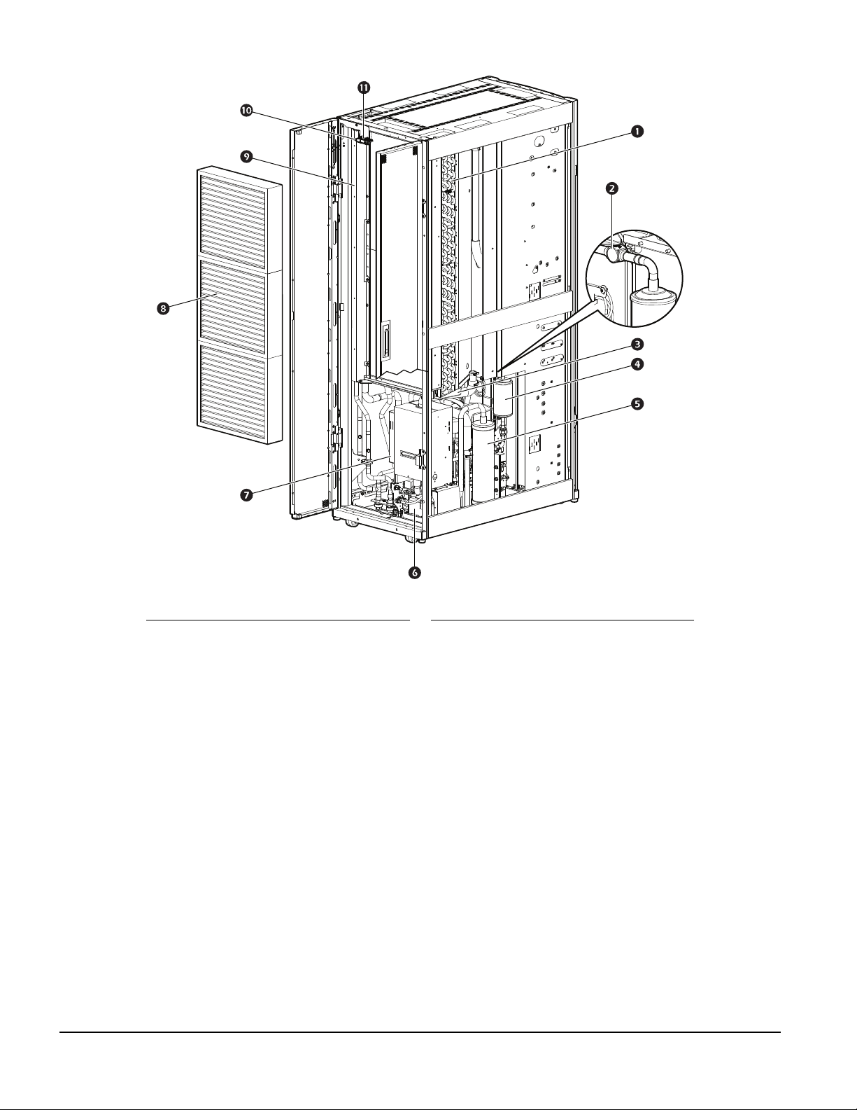
Interior components (ACRD60x)
Front
Item Description Item Description
Condensate drain pan
Electronic expansion valve
Compressor
Variable frequency drive (for
compressor)
Supply air temperature sensor
Main circuit breaker
Fan (2)
Fan guard (2)
Electrical panel
Communication and external device
connectors
Ground lug
Humidity sensor
na5823a
7InRow RD Installation Manual

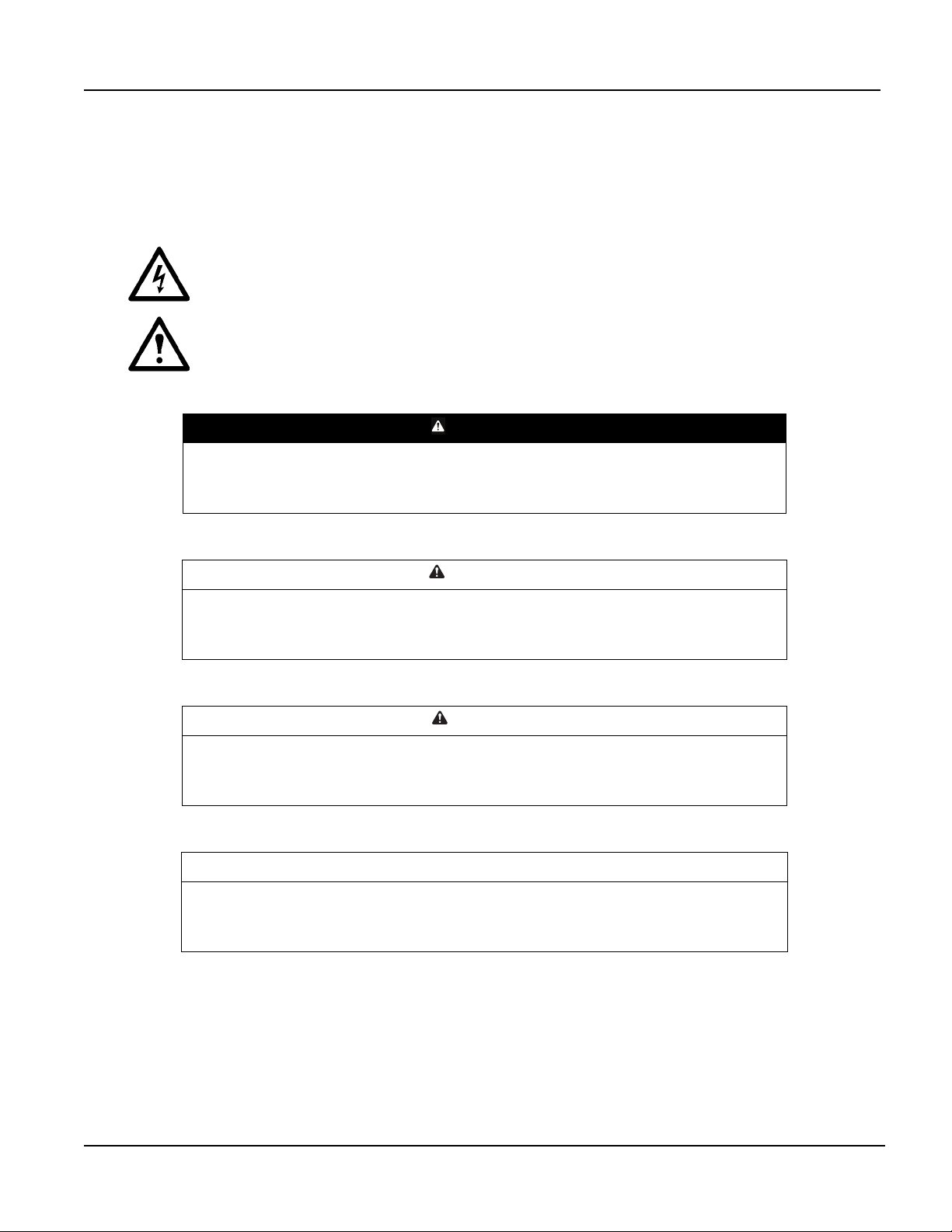
Rear
Item Description Item Description
Evaporator coil
Sight glass
Condensate drain pan
Filter drier
Oil separator
Condensate pump
Air filters
Pipe chase
Return air temperature sensor
na5824a
InRow RD Installation Manual8

Interior components (ACRD60xP)
Front
Item Description Item Description
Electric heater
Condensate drain pan
Electronic expansion valve
Humidifier
Compressor
Main circuit breaker
Fan (2)
Fan guard (2)
Electrical panel
Communication and external device
connectors
Variable frequency drive (for compressor)
Supply air temperature sensor
Ground lug
Humidity sensor
na5821a
9InRow RD Installation Manual
Rear
Item Description Item Description
Evaporator coil
Sight glass
Condensate drain pan
Filter drier
Oil separator
Condensate pump
Humidifier
Air filters
Pipe chase
Humidity sensor
Return air temperature sensor
na5822a
InRow RD Installation Manual10
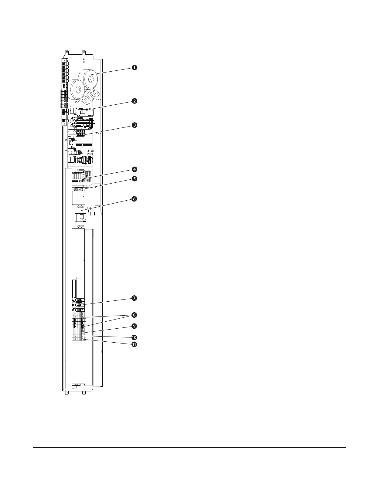
Electrical panel
ACRD600, ACRD601, ACRD602
Item Description
Transformers
Display interface connectors
Main controller board
Relay board
Ground lug
Main circuit breaker
Compressor fuse block
(ACRD600, ACRD601)
Compressor circuit breaker
(ACRD602)
Fan circuit breakers
Fuse not populated
Transformer A fuse
Transformer C/MB fuse
na2724b
11InRow RD Installation Manual

ACRD600P, ACRD601P, ACRD602P
Item Description
Transformers
Display interface connectors
Main controller board
Relay board
Ground lug
Main circuit breaker
Compressor fuse block
(ACRD600P, ACRD601P)
Compressor circuit breaker
(ACRD602P)
Fan circuit breakers
Controller fuse
Heater circuit breaker
Humidifier circuit fuse
Heater contactors
Humidifier contactor
na2032b
InRow RD Installation Manual12

Refrigeration piping diagram
BOTTOM PIPING TOP PIPING
CONDENSER
HOT GAS
HOT GAS
LIQUID
RD
RECEIVER
RD
Item Description Item Description
Pitch in direction of refrigerant flow Pressure relief valve
Reduction of piping diameter for
P-trap
vertical piping run (if necessary)
Shutoff valves S-trap
CONDENSER
LIQUID
na2543a
RECEIVER
Head pressure control valve Inverted P-trap
Check valve
NOTE: All lines are Type L ACR hard-drawn copper pipes.
NOTE: Shutoff valves shown nearest to the condenser are provided in receiver kit.
NOTE: Pitch all lines in the direction of refrigerant flow: 4 mm per m (1/2 in. per 10 ft).
NOTE: Route piping through the top or bottom of the InRow RD cooling unit.
NOTE: Trap the vertical discharge line every 6 m (20 ft) to ensure proper oil return.
NOTE: The maximum piping run is 91 m (300 ft) equivalent length. Size the piping pursuant to accepted
refrigeration practice.
NOTE: Condenser can be placed up to 4.5 m (15 ft) below the indoor cooling unit for equivalent line lengths of
8 m (25 ft) or less.
For Condensers Mounted Below the Level of the Indoor Unit
Piping Equivalent Length – m (ft)
91 (300) 76 (250) 61 (200) 46 (150) 30 (100) 15 (50) 8 (25)
Allowable Distance From Bottom
of Condenser to Bottom of
0.3 (1) 1.5 (5) 2.1 (7) 2.7 (9) 3.3 (11) 3.9 (13) 4.5 (15)
Indoor Unit* – m (ft)
*When condenser is installed below unit level, use 7/8 in. pipe for liquid line.
Note: Condenser can be placed higher than indoor cooling unit but height shall be no more than 27 m (90 ft), regardless
of piping length.
13InRow RD Installation Manual

Connections overview
All connections to and from the equipment can be made through either the top or the bottom of the equipment.
Once the corresponding connectors are sweated or soldered into place, the equipment can be disconnected
without additional soldering, welding, or gluing. See the following tables for information about the sizes and
types of connectors.
Power connections
Minimum
Circuit
Ampacity
Model Voltage
ACRD600 200-240 V,
50/60 Hz
ACRD601 460-480 V,
60 Hz
ACRD602 380-415 V,
50/60 Hz
ACRD600P 200-240 V,
50/60 Hz
ACRD601P 460-480 V,
60 Hz
ACRD602P 380-415 V,
50/60 Hz
*Consult local and national codes for wire size, conduit requirements, and overload protection.
(MCA)
51.6 80 - 29.7* 36.6 14.6
24.0 40 - 28.1* 16.6 14.6
30.7 50 25.2 28.1* 16.6 14.6
77.6 110 - 29.7* 36.6 23.5
36.5 50 - 28.1* 16.6 23.5
45.4 65 34.2 28.1* 16.6 23.5
Maximum
Overload
Protection
(MOP)
Full Load
Amperes
(FLA)
Locked Rotor
Amperes (LRA)
Piping connections
Connection Type
ACRD600
ACRD600P
ACRD601
ACRD601P
Compressor
Compressor
Rated Load
Amperes (RLA)
Power
(kW)
ACRD602
ACRD602P
Refrigerant discharge
Refrigerant liquid
Humidifier water supply
(ACRD600P, ACRD601P,
ACRD602P only)
Condensate drain Quick coupling
* Use a new Teflon gasket (supplied) to prevent leakage. Tighten Rotalock nut to 90 Nm (66 ft-lb).
1 1/4-in. Rotalock*
1 1/4-in. Rotalock*
Quick coupling 1/4-in. NPT or
3/4-in. ID 3/4-in. ID 3/4-in. ID
3/4-in. ID 3/4-in. ID 3/4-in. ID
1/4-in. NPT 1/4-in. BSPT
1/4-in. BSPT
1/2-in. female NPT or
1/2-in. female BSPT
1/2-in. female NPT or
1/2-in. female BSPT
1/2-in. female NPT or
1/2-in. female BSPT
InRow RD Installation Manual14

Communication connections
Wire Size
Torque
Connection Type
Rack temperature 1 RJ-45 - - -
Rack temperature 2 RJ-45 - - -
Rack temperature 3 RJ-45 - - -
A-Link IN RJ-45 - - -
A-Link OUT RJ-45 - - -
Network port RJ-45 - - -
Customer output, Normally Closed (NC) Screw connector AWG 24 (0.2 mm2) AWG 18
Customer output, Common (COM) Screw connector AWG 24 (0.2 mm2) AWG 18
Customer output, Normally Open (NO) Screw connector AWG 24 (0.2 mm2) AWG 18
Supply GND Screw connector AWG 24 (0.2 mm2) AWG 18
Supply 12 Vdc Screw connector AWG 24 (0.2 mm2) AWG 18
Supply 24 Vdc Screw connector AWG 24 (0.2 mm2) AWG 18
Customer input + Screw connector AWG 24 (0.2 mm2) AWG 18
Customer input – Screw connector AWG 24 (0.2 mm2) AWG 18
Modbus D1 Screw connector AWG 24 (0.2 mm2) AWG 18
Modbus D0 Screw connector AWG 24 (0.2 mm2) AWG 18
Modbus GND Screw connector AWG 24 (0.2 mm2) AWG 18
Minimum Maximum
0.6 Nm
(0.75 mm2)
0.6 Nm
(0.75 mm2)
0.6 Nm
(0.75 mm2)
0.6 Nm
(0.75 mm2)
0.6 Nm
(0.75 mm2)
0.6 Nm
(0.75 mm2)
0.6 Nm
(0.75 mm2)
0.6 Nm
(0.75 mm2)
0.6 Nm
(0.75 mm2)
0.6 Nm
(0.75 mm2)
0.6 Nm
(0.75 mm2)
15InRow RD Installation Manual

Room Preparation
During the design of the data center, consider ease of entry for the equipment, floor loading factors, and
accessibility to piping and wiring. In addition, the room temperature and humidity combination should conform
to the environmental operating envelope as defined in the following graphics.
90
80
70
60
50
40
30
20
10
0
10 15 20 25 30 35 40 45 50
RELATIVE HUMIDITY (% RH)
ACCEPTABLE
OPERATING
RANGE
AMBIENT TEMPERATURE (°C) AMBIENT TEMPERATURE (°F)
UNACCEPTABLE
OPERATING LIMITS
90
80
70
60
50
40
30
20
10
ACCEPTABLE
OPERATING
RANGE
0
60 65 70 75 80 85 90 95 100 105 110 115
UNACCEPTABLE
OPERATING LIMITS
RELATIVE HUMIDITY (% RH)
Seal the room with a vapor barrier to minimize moisture infiltration. Polyethylene film is recommended for
ceiling and wall applications. Apply rubber- or plastic-based paints to concrete walls and floors.
Insulate the room to minimize the influence of exterior heat loads. Reduce fresh air to the minimum required by
local and national codes and regulations. Fresh air imposes extreme load variation on the cooling equipment
from summer to winter and causes increased system operating costs.
Air distribution
The equipment distributes air in a back-to-front discharge pattern, removing hot air from a hot aisle and
discharging cooled air into a cold aisle.
NOTE: The equipment is designed for free air discharge or for use with the Rack Air Containment System or
EcoAisle Containment System. The equipment is not intended to be connected to a duct system.
na2544a
Incoming power supply requirement
ELECTRICAL HAZARD
• Electrical service must conform to local and national electrical codes and regulations.
• The equipment must be grounded.
Failure to follow these instructions can result in death, serious injury, or
equipment damage.
WARNING
InRow RD Installation Manual16
 Loading...