Schneider Electric Altivar12 User Manual

Altivar 12
Variable speed drives for asynchronous motors
Modbus Communication Manual
04/2009
BBV28590
www.schneider-electric.com

Contents
Important Information __________________________________________________________________________________________ 4 Before you begin______________________________________________________________________________________________ 5 Documentation structure________________________________________________________________________________________ 6 Presentation _________________________________________________________________________________________________ 7 Connection to RS485 bus_______________________________________________________________________________________ 8 Configuration of the Modbus serial port ____________________________________________________________________________ 9 IO Scanner configuration parameters_____________________________________________________________________________ 10 Modbus Functions ___________________________________________________________________________________________ 12 ATV12 state machine _________________________________________________________________________________________ 17 Application example __________________________________________________________________________________________ 21 Connection to RS485 bus______________________________________________________________________________________ 24
BBV28590 04/2009 |
3 |

Important Information
NOTICE
Read these instructions carefully, and look at the equipment to become familiar with the device before trying to install, operate, or maintain it. The following special messages may appear throughout this documentation or on the equipment to warn of potential hazards or to call attention to information that clarifies or simplifies a procedure.
The addition of this symbol to a Danger or Warning safety label indicates that an electrical hazard exists, which will result in personal injury if the instructions are not followed.
This is the safety alert symbol. It is used to alert you to potential personal injury hazards. Obey all safety messages that follow this symbol to avoid possible injury or death.
 DANGER
DANGER indicates an imminently hazardous situation, which, if not avoided, will result in death or serious injury.
WARNING
WARNING indicates a potentially hazardous situation, which, if not avoided, can result in death or serious injury.
CAUTION
CAUTION indicates a potentially hazardous situation, which, if not avoided, can result in minor or moderate injury.
CAUTION
CAUTION, used without the safety alert symbol, indicates a potentially hazardous situation which, if not avoided, can result in property damage.
PLEASE NOTE
The word "drive" as used in this manual refers to the controller portion of the adjustable speed drive as defined by NEC.
Electrical equipment should be installed, operated, serviced, and maintained only by qualified personnel. No responsibility is assumed by Schneider Electric for any consequences arising out of the use of this material.
© 2009 Schneider Electric. All Rights Reserved
4 |
BBV28590 04/2009 |

Before you begin
Read and understand these instructions before performing any procedure with this drive.

 DANGER
HAZARD OF ELECTRIC SHOCK, EXPLOSION, OR ARC FLASH
•Read and understand this manual before installing or operating the Altivar 12 drive. Installation, adjustment, repair, and maintenance must be performed by qualified personnel.
•The user is responsible for compliance with all international and national electrical code requirements with respect to grounding of all equipment.
•Many parts of this drive, including the printed circuit boards, operate at the line voltage. DO NOT TOUCH. Use only electrically insulated tools.
•DO NOT touch unshielded components or terminal strip screw connections with voltage present.
•DO NOT short across terminals PA/+ and PC/– or across the DC bus capacitors.
•Before servicing the drive:
-Disconnect all power, including external control power that may be present.
-Place a “DO NOT TURN ON” label on all power disconnects.
-Lock all power disconnects in the open position.
-WAIT 15 MINUTES to allow the DC bus capacitors to discharge. Then follow the “Bus Voltage Measurement Procedure” (see User manual) to verify that the DC voltage is less than 42 V. The drive LEDs are not indicators of the absence of DC bus voltage.
•Install and close all covers before applying power or starting and stopping the drive.
Failure to follow these instructions will result in death or serious injury.
 DANGER
UNINTENDED EQUIPMENT OPERATION
•Read and understand this manual before installing or operating the Altivar 12 drive.
•Any changes made to the parameter settings must be performed by qualified personnel.
Failure to follow these instructions will result in death or serious injury.
 WARNING
DAMAGED DRIVE EQUIPMENT
Do not operate or install any drive or drive accessory that appears damaged.
Failure to follow these instructions can result in death, serious injury, or equipment damage.
 WARNING
LOSS OF CONTROL
•The designer of any control scheme must
-consider the potential failure modes of control paths and, for certain critical control functions,
-provide a means to achieve a safe state during and after a path failure.
Examples of critical control functions are emergency stop and overtravel stop.
•Separate or redundant control paths must be provided for critical control functions.
•System control paths may include communication links. Consideration must be given to the implications of unanticipated transmission delays or failures of the link.a
Failure to follow these instructions can result in death, serious injury, or equipment damage.
a. For additional information, refer to NEMA ICS 1.1 (latest edition), “Safety Guidelines for the Application, Installation, and Maintenance of Solid State Control” and to NEMA ICS 7.1 (latest edition), “Safety Standards for Construction and Guide for Selection, Installation and Operation of Adjustable-Speed Drive Systems.”
BBV28590 04/2009 |
5 |

Documentation structure
The following Altivar 312 technical documents are available on the Schneider Electric website (www.schneider-electric.com) as well as on DVD-ROM (reference VW3A8200).
User manual
This manual describes how to install, commission, operate and program the drive.
Simplified manual
This manual is a simplified version of the User manual. This manual is delivered with the drive.
Quick Start sheet
The Quick Start describes how to wire and configure the drive to start motor quickly and simply for simple applications. This document is delivered with the drive.
Modbus Communication manual
This manual describes the assembly, connection to the bus or network, signaling, diagnostics, and configuration of the communicationspecific parameters via the 7 segment LED display.
It also describes the communication services of the Modbus protocol. This manual includes the main Modbus addresses.
It explains the operating mode specific to communication (state chart).
ATV12P manual
This manual describes the features related to products mounted on baseplate.
ATV12 Parameters description file
All the parameters are grouped together in an Excel file available on the Schneider Electric website (www.schneider-electric.com), with the following data:
•Code
•Name
•Modbus Addresses
•Category
•Read/write access
•Type: signed numerical, unsigned numerical, etc.
•Unit
•Factory setting
•Minimum value
•Maximum value
•Display on the 7-segment integrated display terminal
•Relevant menu
This file offers the option of sorting and arranging the data according to any criterion chosen by the user.

 DANGER
UNINTENDED EQUIPMENT OPERATION
•Read and understand this manual before installing or operating the Altivar 12 drive.
•Any changes made to the parameter settings must be performed by qualified personnel.
•The excel file does not describe the behaviour of the parameters. Before any modification, refer to the ATV12 User Manual.
Failure to follow these instructions will result in death or serious injury.
6 |
BBV28590 04/2009 |

Presentation
The Modbus socket on the Altivar 12 can be used for the following functions:
•Configuration
•Settings
•Control
•Monitoring
The ATV12 drive supports:
•The 2-wire RS485 physical layer
•The RTU transmission mode
BBV28590 04/2009 |
7 |

Connection to RS485 bus
Connection to ATV12
Connection accessories should be ordered separately (please consult our catalogues).
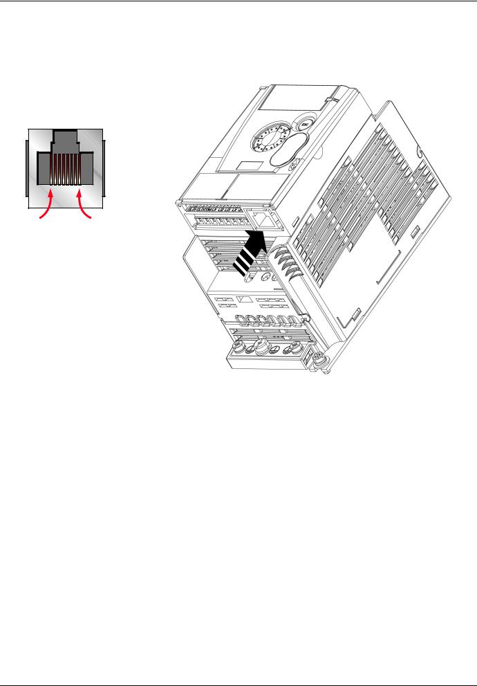
Connect the RJ45 cable connector to the ATV12 connector.
Pin out of the ATV12 RJ45 Connector
View from underneath
8........................1 |
Pin |
Signal |
|
|
1 |
- |
|
|
2 |
- |
|
|
3 |
- |
|
|
4 |
D1 (1) |
|
|
5 |
D0 (1) |
|
|
6 |
- |
|
|
7 |
VP (2) |
|
|
8 |
Common (1) |
|
|
(1)Modbus signals
(2) Supply for RS232 / RS485 converter or a remote terminal
Protection against interference
•Use the Schneider Electric cable with 2 pairs of shielded twisted conductors (reference: TSXCSA100, TSXCSA200, TSXCSA500).
•Keep the Modbus cable separated from the power cables (30 cm (11.8 in.) minimum).
•Make any crossovers of the Modbus cable and the power cables at right-angles, if necessary.
For more information, please refer to the TSX DG KBL E manual: "Electromagnetic compatibility of industrial networks and fieldbuses".
RS485 bus schematic
The RS485 standard allows variants of different characteristics:
•polarisation
•line terminator
•distribution of a reference potential
•number of slaves
•length of bus
The new Modbus specification published on the Modbus.org site in 2002 contains precise details of all these characteristics. They are also summarised in Standard schematic section. The new Schneider Electric devices conform to this specification.
8 |
BBV28590 04/2009 |
 Loading...