


Schneider Electric iEM3200, iEM3300, iEM3100 User Manual

iEM3100 / iEM3200 / iEM3300 series
Energy meters
User manual
DOCA0005EN-04
04/2014
www.schneider-electric.com


iEM3100 / iEM3200 / iEM3300 series user manual
The information provided in this documentation contains general descriptions and/or technical
characteristics of the performance of the products contained herein. This documentation is not
intended as a substitute for and is not to be used for determining suitability or reliability of these
products for specific user applications. It is the duty of any such user or integrator to perform the
appropriate and complete risk analysis, evaluation and testing of the products with respect to the
relevant specific application or use thereof. Neither Schneider Electric nor any of its affiliates or
subsidiaries shall be responsible or liable for misuse of the information contained herein. If you have
any suggestions for improvements or amendments or have found errors in this publication, please
notify us.
No part of this document may be reproduced in any form or by any means, electronic or mechanical,
including photocopying, without express written permission of Schneider Electric.
All pertinent state, regional, and local safety regulations must be observed when installing and using
this product. For reasons of safety and to help ensure compliance with documented system data, only
the manufacturer should perform repairs to components.
When devices are used for applications with technical safety requirements, the relevant instructions
must be followed.
Failure to use Schneider Electric software or approved software with our hardware products may
result in injury, harm, or improper operating results.
Failure to observe this information can result in injury or equipment damage.
© 2014 Schneider Electric. All rights reserved.
DOCA0005EN-04 3
Safety information
iEM3100 / iEM3200 / iEM3300 series user manual
Important information
Read these instructions carefully and look at the equipment to become familiar with the device
before trying to install, operate, service or maintain it. The following special messages may
appear throughout this bulletin or on the equipment to warn of potential hazards or to call
attention to information that clarifies or simplifies a procedure.
The addition of either symbol to a “Danger” or “Warning” safety label indicates that an electrical
hazard exists which will result in personal injury if the instructions are not followed.
This is the safety alert symbol. It is used to alert you to potential personal injury hazards. Obey all
safety messages that follow this symbol to avoid possible injury or death.
DANGER
DANGER indicates an imminently hazardous situation which, if not avoided, will result in death or
serious injury.
WARNING
WARNING indicates a potentially hazardous situation which, if not avoided, can result in death or
serious injury.
CAUTION
CAUTION indicates a potentially hazardous situation which, if not avoided, can result in minor or
moderate injury.
NOTICE
NOTICE is used to address practices not related to physical injury. The safety alert symbol shall not
be used with this signal word.
Please note
Electrical equipment should be installed, operated, serviced and maintained only by qualified
personnel. No responsibility is assumed by Schneider Electric for any consequences arising out of the
use of this material.
A qualified person is one who has skills and knowledge related to the construction, installation, and
operation of electrical equipment and has received safety training to recognize and avoid the hazards
involved.
4 DOCA0005EN-04

iEM3100 / iEM3200 / iEM3300 series user manual
Notices
FCC Part 15 notice
This equipment has been tested and found to comply with the limits for a Class B digital device,
pursuant to part 15 of the FCC Rules. These limits are designed to provide reasonable protection
against harmful interference in a residential installation. This equipment generates, uses, and can
radiate radio frequency energy and, if not installed and used in accordance with the instructions, may
cause harmful interference to radio communications. However, there is no guarantee that interference
will not occur in a particular installation. If this equipment does cause harmful interference to radio or
television reception, which can be determined by turning the equipment off and on, the user is
encouraged to try to correct the interference by one or more of the following measures:
• Reorient or relocate the receiving antenna.
• Increase the separation between the equipment and receiver.
• Connect the equipment to an outlet on a circuit different from that to which the receiver is
connected.
• Consult the dealer or an experienced radio/TV technician for help.
This Class B digital apparatus complies with Canadian ICES-003.
DOCA0005EN-04 5

About the book
iEM3100 / iEM3200 / iEM3300 series user manual
Document scope
This manual is intended for use by designers, system builders and maintenance technicians with an
understanding of electrical distribution systems and monitoring devices.
Validity note
The meters are used to measure the amount of active energy consumed by an installation or a part of
an installation.
This function meets the requirements for:
• consumption monitoring,
• evaluation of energy items (cost, accounting, etc.).
This function may also satisfy the power-saving incentives implemented by many countries.
Related documents
Title of documentation Reference number
Installation sheet: iEM3100 / iEM3110 / iEM3115 S1B46581 / S1B62907
Installation sheet: iEM3150 / iEM3155 S1B46583 / S1B62908
Installation sheet: iEM3200 / iEM3210 / iEM3215 S1B46598 / S1B62910
Installation sheet: iEM3250 / iEM3255 S1B46602 / S1B62911
Installation sheet: iEM3135 HRB68964 / HRB72100
Installation sheet: iEM3165 HRB68991 / HRB72106
Installation sheet: iEM3175 HRB68988 / HRB72103
Installation sheet: iEM3235 HRB68995 / HRB72108
Installation sheet: iEM3265 HRB69003 / HRB72111
Installation sheet: iEM3275 HRB68999 / HRB72109
Installation sheet iEM3310 / iEM3350 HRB91204 / HRB91205
Installation sheet iEM3335 / iEM3355 / iEM3365 / iEM3375 HRB91202 / HRB91203
You can download these technical publications and other technical information from www.schneiderelectric.com.
6 DOCA0005EN-04

iEM3100 / iEM3200 / iEM3300 series user manual
Contents
Safety information . . . . . . . . . . . . . . . . . . . . . . . . . . . . . . . . . . . . . . . . . . . . . . . . . . . . . . 4
Notices . . . . . . . . . . . . . . . . . . . . . . . . . . . . . . . . . . . . . . . . . . . . . . . . . . . . . . . . . . . . . . . 5
About the book . . . . . . . . . . . . . . . . . . . . . . . . . . . . . . . . . . . . . . . . . . . . . . . . . . . . . . . . 6
Contents . . . . . . . . . . . . . . . . . . . . . . . . . . . . . . . . . . . . . . . . . . . . . . . . . . . . . . . . . . . . . . .7
Chapter 1 Safety precautions . . . . . . . . . . . . . . . . . . . . . . . . . . . . . . . . . . . . . . . . . . 9
Chapter 2 Overview . . . . . . . . . . . . . . . . . . . . . . . . . . . . . . . . . . . . . . . . . . . . . . . . . 11
Overview of meter functions . . . . . . . . . . . . . . . . . . . . . . . . . . . . . . . . . . . . . . . . . . . . 11
Typical applications . . . . . . . . . . . . . . . . . . . . . . . . . . . . . . . . . . . . . . . . . . . . . . . . . . . 13
Chapter 3 Hardware and installation . . . . . . . . . . . . . . . . . . . . . . . . . . . . . . . . . . . 15
Dimensions . . . . . . . . . . . . . . . . . . . . . . . . . . . . . . . . . . . . . . . . . . . . . . . . . . . . . . . . . . 15
Hardware overview . . . . . . . . . . . . . . . . . . . . . . . . . . . . . . . . . . . . . . . . . . . . . . . . . . . . 16
DIN rail mounting and dismounting . . . . . . . . . . . . . . . . . . . . . . . . . . . . . . . . . . . . . . 22
Input, output and communications wiring . . . . . . . . . . . . . . . . . . . . . . . . . . . . . . . . . 24
Power system wiring . . . . . . . . . . . . . . . . . . . . . . . . . . . . . . . . . . . . . . . . . . . . . . . . . . . 26
Chapter 4 Front panel display and meter setup . . . . . . . . . . . . . . . . . . . . . . . . . . 33
Overview . . . . . . . . . . . . . . . . . . . . . . . . . . . . . . . . . . . . . . . . . . . . . . . . . . . . . . . . . . . . 33
Data display . . . . . . . . . . . . . . . . . . . . . . . . . . . . . . . . . . . . . . . . . . . . . . . . . . . . . . . . . . 33
Resets . . . . . . . . . . . . . . . . . . . . . . . . . . . . . . . . . . . . . . . . . . . . . . . . . . . . . . . . . . . . . . . 36
Multi Tariff feature . . . . . . . . . . . . . . . . . . . . . . . . . . . . . . . . . . . . . . . . . . . . . . . . . . . . . 36
Meter status information . . . . . . . . . . . . . . . . . . . . . . . . . . . . . . . . . . . . . . . . . . . . . . . 37
The device clock . . . . . . . . . . . . . . . . . . . . . . . . . . . . . . . . . . . . . . . . . . . . . . . . . . . . . . 37
Device configuration . . . . . . . . . . . . . . . . . . . . . . . . . . . . . . . . . . . . . . . . . . . . . . . . . . . 38
Modifying parameters . . . . . . . . . . . . . . . . . . . . . . . . . . . . . . . . . . . . . . . . . . . . . . . . . . 39
Configuration mode menus . . . . . . . . . . . . . . . . . . . . . . . . . . . . . . . . . . . . . . . . . . . . . 40
Chapter 5 Communications via Modbus RS-485 . . . . . . . . . . . . . . . . . . . . . . . . . 51
Modbus communication overview . . . . . . . . . . . . . . . . . . . . . . . . . . . . . . . . . . . . . . . . 51
Modbus functions . . . . . . . . . . . . . . . . . . . . . . . . . . . . . . . . . . . . . . . . . . . . . . . . . . . . . 52
Command interface . . . . . . . . . . . . . . . . . . . . . . . . . . . . . . . . . . . . . . . . . . . . . . . . . . . . 53
Modbus register list . . . . . . . . . . . . . . . . . . . . . . . . . . . . . . . . . . . . . . . . . . . . . . . . . . . 57
Read Device Identification . . . . . . . . . . . . . . . . . . . . . . . . . . . . . . . . . . . . . . . . . . . . . . 61
Chapter 6 Communications via LonWorks . . . . . . . . . . . . . . . . . . . . . . . . . . . . . . 63
LonWorks communications overview . . . . . . . . . . . . . . . . . . . . . . . . . . . . . . . . . . . . . 63
LonWorks communication implementation . . . . . . . . . . . . . . . . . . . . . . . . . . . . . . . . 63
Standard network variable types (SNVTs) and configuration properties for reading
data . . . . . . . . . . . . . . . . . . . . . . . . . . . . . . . . . . . . . . . . . . . . . . . . . . . . . . . . . . . . . . . . . 64
Meter configuration properties . . . . . . . . . . . . . . . . . . . . . . . . . . . . . . . . . . . . . . . . . . 68
Echelon LonMaker plug-in for data display and meter configuration . . . . . . . . . . . 71
DOCA0005EN-04 7

iEM3100 / iEM3200 / iEM3300 series user manual
Chapter 7 Communications via M-Bus . . . . . . . . . . . . . . . . . . . . . . . . . . . . . . . . . 75
M-Bus communications overview . . . . . . . . . . . . . . . . . . . . . . . . . . . . . . . . . . . . . . . . 75
M-Bus protocol support . . . . . . . . . . . . . . . . . . . . . . . . . . . . . . . . . . . . . . . . . . . . . . . . . 76
M-Bus protocol implementation . . . . . . . . . . . . . . . . . . . . . . . . . . . . . . . . . . . . . . . . . . 76
Variable data structure telegram information . . . . . . . . . . . . . . . . . . . . . . . . . . . . . . . 77
Telegram information for data records . . . . . . . . . . . . . . . . . . . . . . . . . . . . . . . . . . . . 79
Telegram information for meter configuration . . . . . . . . . . . . . . . . . . . . . . . . . . . . . . 82
M-Bus tool for data display and meter configuration . . . . . . . . . . . . . . . . . . . . . . . . . 85
Chapter 8 Communications via BACnet . . . . . . . . . . . . . . . . . . . . . . . . . . . . . . . . 89
BACnet communications overview . . . . . . . . . . . . . . . . . . . . . . . . . . . . . . . . . . . . . . . 89
BACnet protocol support . . . . . . . . . . . . . . . . . . . . . . . . . . . . . . . . . . . . . . . . . . . . . . . 89
BACnet communications implementation . . . . . . . . . . . . . . . . . . . . . . . . . . . . . . . . . . 90
BACnet object and property information . . . . . . . . . . . . . . . . . . . . . . . . . . . . . . . . . . . 91
Chapter 9 Specifications . . . . . . . . . . . . . . . . . . . . . . . . . . . . . . . . . . . . . . . . . . . . 97
Electrical characteristics . . . . . . . . . . . . . . . . . . . . . . . . . . . . . . . . . . . . . . . . . . . . . . . . 97
Mechanical characteristics . . . . . . . . . . . . . . . . . . . . . . . . . . . . . . . . . . . . . . . . . . . . . . 99
Environmental characteristics . . . . . . . . . . . . . . . . . . . . . . . . . . . . . . . . . . . . . . . . . . . 99
Measurement accuracy . . . . . . . . . . . . . . . . . . . . . . . . . . . . . . . . . . . . . . . . . . . . . . . . . 99
MID . . . . . . . . . . . . . . . . . . . . . . . . . . . . . . . . . . . . . . . . . . . . . . . . . . . . . . . . . . . . . . . . . 100
Internal clock . . . . . . . . . . . . . . . . . . . . . . . . . . . . . . . . . . . . . . . . . . . . . . . . . . . . . . . . 100
Modbus communications . . . . . . . . . . . . . . . . . . . . . . . . . . . . . . . . . . . . . . . . . . . . . . 100
LonWorks communications . . . . . . . . . . . . . . . . . . . . . . . . . . . . . . . . . . . . . . . . . . . . 100
M-Bus communications . . . . . . . . . . . . . . . . . . . . . . . . . . . . . . . . . . . . . . . . . . . . . . . . 101
BACnet communications . . . . . . . . . . . . . . . . . . . . . . . . . . . . . . . . . . . . . . . . . . . . . . . 101
Chapter 10 Troubleshooting . . . . . . . . . . . . . . . . . . . . . . . . . . . . . . . . . . . . . . . . . 103
Diagnosis screen . . . . . . . . . . . . . . . . . . . . . . . . . . . . . . . . . . . . . . . . . . . . . . . . . . . . . 103
Diagnostic codes . . . . . . . . . . . . . . . . . . . . . . . . . . . . . . . . . . . . . . . . . . . . . . . . . . . . . 104
Chapter 11 Power, energy and power factor . . . . . . . . . . . . . . . . . . . . . . . . . . . . 105
Power (PQS) . . . . . . . . . . . . . . . . . . . . . . . . . . . . . . . . . . . . . . . . . . . . . . . . . . . . . . . . . 105
Energy delivered (imported) / energy received (exported) . . . . . . . . . . . . . . . . . . . . 106
Power factor (PF) . . . . . . . . . . . . . . . . . . . . . . . . . . . . . . . . . . . . . . . . . . . . . . . . . . . . . 106
Power factor register format . . . . . . . . . . . . . . . . . . . . . . . . . . . . . . . . . . . . . . . . . . . . 108
8 DOCA0005EN-04

iEM3100 / iEM3200 / iEM3300 series user manual Safety precautions
Chapter 1 Safety precautions
Installation, wiring, testing and service must be performed in accordance with all local and national
electrical codes.
Carefully read and follow the safety precautions outlined below.
DANGER
HAZARD OF ELECTRIC SHOCK, EXPLOSION, OR ARC FLASH
• Apply appropriate personal protective equipment (PPE) and follow safe electrical work practices.
See NFPA 70E in the USA or applicable local standards.
• This equipment must only be installed and serviced by qualified electrical personnel.
• Turn off all power supplying this device and the equipment in which it is installed before working
on the device or equipment.
• Always use a properly rated voltage sensing device to confirm power is off.
• Before performing visual inspections, tests, or maintenance on this equipment, disconnect all
sources of electric power. Assume that all circuits are live until they have been completely
de-energized, tested and tagged. Pay particular attention to the design of the power system.
Consider all power supply sources, particularly the potential for backfeed.
• Replace all devices, doors and covers before turning on power to this equipment.
• Do not exceed the device’s ratings for maximum limits.
Failure to follow these instructions will result in death or serious injury.
WARNING
UNINTENDED OPERATION
Do not use the meter for critical control or protection applications where human or equipment safety
relies on the operation of the control circuit.
Failure to follow these instructions can result in death, serious injury or equipment damage.
WARNING
INACCURATE DATA RESULTS
• Do not rely solely on data displayed on the front panel or in software to determine if the device is
functioning correctly or compliant with all applicable standards.
• Do not use data displayed on the front panel or in software as a substitute for proper workplace
practices or equipment maintenance.
Failure to follow these instructions can result in death, serious injury or equipment damage.
DOCA0005EN-04 9

Safety precautions iEM3100 / iEM3200 / iEM3300 series user manual
10 DOCA0005EN-04

iEM3100 / iEM3200 / iEM3300 series user manual Overview
Chapter 2 Overview
What is in this chapter?
This chapter contains the following topics:
Overview of meter functions . . . . . . . . . . . . . . . . . . . . . . . . . . . . . . . . . . . . . . . . . . . . . 11
Typical applications . . . . . . . . . . . . . . . . . . . . . . . . . . . . . . . . . . . . . . . . . . . . . . . . . . . . 13
Overview of meter functions
The meters provide the essential measurement capabilities (for example, current, voltage, and
energy) required to monitor a 1- or 3-phase electrical installation.
The key features of the meters are:
• measurement of active and reactive energy,
• Multi Tariffs (up to 4) controlled by internal clock, digital inputs or communication,
• MID compliance for many of the meters,
• pulse outputs,
• display (current, voltage, and energy measurements),
• communications via Modbus, LonWorks, M-Bus or BACnet protocols.
Main characteristics
63 A meters
Function
Direct measurement (up to 63 A)
Active Energy measurement accuracy class (total and
partial kWh)
Four Quadrant Energy measurements
Electrical measurements (I, V, P, ...)
Controlled by internal clock
Multi Tariff
Measurement display (number of lines)
Digital inputs
Digital outputs
Overload alarm
Communications
MID compliant
Width (18 mm module in DIN rail mounting)
Controlled by digital input(s)
Controlled by communications
Programmable (status, tariff
control, or input monitoring)
Tariff control only
Programmable (energy pulsing
or overload alarm)
Pulse output only
Modbus
LonWorks
M-Bus
BACnet
iEM3135
iEM3150
iEM3155
iEM3165
iEM3100
iEM3110
iEM3115
11111111
––– –
–––
––44–444
––42–222
–––4–444
33333333
–––1–111
––2–––––
–––1–11–
–1––––––
––– –
––––––
–––––––
––– ––––
–––––– –
– –
55555555
iEM3175
DOCA0005EN-04 11

Overview iEM3100 / iEM3200 / iEM3300 series user manual
125 A meters
Function
iEM3335
iEM3350
iEM3355
iEM3365
Direct measurement (up to 125 A)
Active Energy measurement accuracy class (total and partial
kWh)
Four Quadrant Energy measurements
Electrical measurements (I, V, P, ...)
Controlled by internal clock
Multi Tariff
Controlled by digital input(s)
Controlled by communications
Measurement display (number of lines)
Digital inputs (programmable for status, tariff control, or input
monitoring)
Programmable (energy pulsing or
Digital outputs
overload alarm)
Pulse output only
Overload alarm
Modbus
LonWorks
Communications
M-Bus
BACnet
MID compliant
Width (18 mm module in DIN rail mounting)
iEM3300
iEM3310
1111111
–– –
––
––4–444
––2–222
––4–444
3333333
––1–111
––1–11–
–1–––––
–– –
–––––
––––––
–– ––––
––––– –
– –
7777777
iEM3375
1 A / 5 A meters
Function
Measurement inputs through CTs (1 A, 5 A)
Measurement inputs through VTs
Active Energy measurement accuracy class (total and
partial kWh)
Four Quadrant Energy measurements
Electrical measurements (I, V, P, ...)
Controlled by internal clock
Multi Tariff
Measurement display (number of lines)
Digital inputs
Digital outputs
Controlled by digital input(s)
Controlled by communications
Programmable (status, tariff
control, or input monitoring)
Tariff control only
Programmable (energy pulsing
or overload alarm)
Pulse output only
iEM3200
iEM3210
iEM3215
iEM3235
iEM3250
iEM3255
iEM3265
iEM3275
–––
0.5S 0.5S 0.5S 0.5S 0.5S 0.5S 0.5S 0.5S
––– –
–––
––44–444
––42–222
–––4–444
33333333
–––1–111
––2–––––
–––1–11–
–1––––––
12 DOCA0005EN-04

iEM3100 / iEM3200 / iEM3300 series user manual Overview
Function
iEM3200
iEM3210
iEM3215
iEM3235
iEM3250
iEM3255
iEM3265
Overload alarm
Modbus
LonWorks
––– –
––––––
–––––––
Communications
M-Bus
BACnet
MID compliant
Width (18 mm module in DIN rail mounting)
––– ––––
–––––– –
– –
55555555
Typical applications
This range is a cost effective solution to monitor feeder circuits. These meters can monitor energy
consumption by usage, by zone or by feeder in the cabinet. They can be used to monitor feeders in a
main switchboard or to monitor the main in a distribution cabinet.
iEM31•• and iEM33•• series
iEM3275
Functions Advantages
Can directly measure feeders up to:
iEM31••: 63 A
iEM33••: 125 A
Embedded current transformers (CTs)
Adapted to be installed with Acti9 iC65 (iEM31••) or Acti9 C120
(iEM33••) circuit breakers
Can be used for single-phase multi-circuit monitoring 3 single feeders can be monitored with a single meter
iEM32•• series
Functions Advantages
CT and VT connection Can be used in low or medium voltage applications
Flexible configuration Can be adapted to any distribution network with or without neutral
Typical applications
The following table presents some of the functions of the different meters, the advantages and main
applications.
Functions Advantages Applications Meter
Total and partial energy counters Energy usage monitoring
Internal clock Saves the date and time of last reset
Pulse output with a configurable
pulse weight of up to 1 pulse per
1 Wh
Manages up to four tariffs,
controlled by the digital input(s),
internal clock or communications
(depending on meter model)
Measures essential electrical
parameters like current, average
voltage and total power.
Collect pulses from the meter with a Smartlink
system, PLC or any basic acquisition system
Categorize energy consumption into On Peak and Off
Peak, working days and weekends, or by different
electricity sources (for example, from the utility and
an electrical generator)
Instantaneous measurements help you monitor the
imbalance between phases.
Total power allows you to monitor the feeder load
level.
Saves installation time and space in the cabinet
No wiring to manage
Clear distribution network
Can be used in three-phase systems with or without neutral
Sub-billing management
Metering applications
Provides the timestamp of the last reset of the
partial energy accumulation
Remote monitoring of energy consumption
Integrate the meter in to a system monitoring of
a large number of devices
Energy demand management
Sub-billing management
Identification of local energy consumption
behavior by zone, by usage or by feeder
Monitoring of feeders or any sub-cabinet
All
All (except iEM3100 /
iEM3200 / iEM3300)
iEM3110 / iEM3310 /
iEM3210
iEM3115 / iEM3135 /
iEM3155 / iEM3165 /
iEM3175
iEM3215 / iEM3235 /
iEM3255 / iEM3265 /
iEM3275
iEM3335 / iEM3355 /
iEM3365 / iEM3375
iEM3135 / iEM3155 /
iEM3165 / iEM3175
iEM3235 / iEM3255 /
iEM3265 / iEM3275
iEM3335 / iEM3355 /
iEM3365 / iEM3375
DOCA0005EN-04 13

Overview iEM3100 / iEM3200 / iEM3300 series user manual
Functions Advantages Applications Meter
M-Bus communications
Modbus communications
BACnet communications
LonWorks communications
Four quadrant calculation
Measurement of active, reactive
and apparent energy.
Programmable digital input
Programmable digital output
Communicate advanced parameters using
M-Bus protocol
Communicate advanced parameters using Modbus
protocol
Communicate advanced parameters using BACnet
MS/TP protocol
Communicate advanced parameters using LonWorks
communications
Identification of imported and exported active and
reactive energy allows you to monitor energy flow in
both directions: delivered from the utility and
produced on-site
Allows you to monitor energy consumption and
production
Can be programmed to:
Count pulses from other meters (gas, water, etc.)
Monitor an external status
Reset the partial energy accumulation and start a
new period of accumulation
Can be programmed to:
be an active energy (kWh) pulse output, with a
configurable pulse weight
Alarm on a power overload at a configurable pickup
setpoint
M-Bus network integration
Modbus network integration
BACnet network integration
LonWorks network integration
Ideal for facilities with back-up generators or
green power capabilities (for example, solar
panels or wind turbines)
Manage energy consumption and make
informed investment to reduce your energy bill
or penalties (for example, installing capacitor
banks)
This allows for monitoring of:
WAGES
Intrusion (for example, doors opening) or
equipment status
Energy usage
This allows you to:
Collect pulses from the meter with a Smartlink
system, PLC or any basic acquisition system
Monitor power levels at a detailed level and to
help detect an overload before the circuit
breaker trips
iEM3135 / iEM3235 /
iEM3335
iEM3150 / iEM3155
iEM3250 / iEM3255
iEM3350 / iEM3355
iEM3165 / iEM3265 /
iEM3365
iEM3175 / iEM3275 /
iEM3375
iEM3135 / iEM3155 /
iEM3165/ iEM3175
iEM3235 / iEM3255 /
iEM3265 / iEM3275
iEM3335 / iEM3355 /
iEM3365 / iEM3375
iEM3135 / iEM3155 /
iEM3165
iEM3235 / iEM3255 /
iEM3265
iEM3335 / iEM3355 /
iEM3365
14 DOCA0005EN-04

iEM3100 / iEM3200 / iEM3300 series user manual Hardware and installation
Chapter 3 Hardware and installation
What is in this chapter?
This chapter contains the following topics:
Dimensions . . . . . . . . . . . . . . . . . . . . . . . . . . . . . . . . . . . . . . . . . . . . . . . . . . . . . . . . . . .15
Hardware overview . . . . . . . . . . . . . . . . . . . . . . . . . . . . . . . . . . . . . . . . . . . . . . . . . . . . . 16
DIN rail mounting and dismounting . . . . . . . . . . . . . . . . . . . . . . . . . . . . . . . . . . . . . . . 22
Input, output and communications wiring . . . . . . . . . . . . . . . . . . . . . . . . . . . . . . . . . . 24
Power system wiring . . . . . . . . . . . . . . . . . . . . . . . . . . . . . . . . . . . . . . . . . . . . . . . . . . . . 26
Dimensions
iEM31•• and iEM32•• meters
A Without communications
B With communications
mm
in
mm
in
N’N
ON
500 /kWh
OK
N’N
90
3.54
iEM33•• meters
ON
200 /kWh
Config
L2’
L2’
87
3.43
45
ESC
Reset
1.77
95.0
3.74
L3’ L3 L2 L1’ L1
101.5
4.00
63.5
2.50
69
2.71
A Without communications
B With communications
93.8
3.70
45
1.77
103.2
OK
ESC
Reset
Config
L3’ L3 L2 L1’ L1L1
4.06
108.4
4.27
63.8
126.0
4.96
69.3
2.73
2.51
DOCA0005EN-04 15

Hardware and installation iEM3100 / iEM3200 / iEM3300 series user manual
Hardware overview
All meters: Meter sealing points
All meters have sealing covers and sealing points to help prevent access to inputs and outputs and
current and voltage connections.
A Sealing points
B Sealable covers
ESC
OK
iEM3100 / iEM3110 / iEM3115 - Direct measurement up to 63 A
The various features of the iEM3100 / iEM3110 / iEM3115 are shown in the diagram below:
A Digital inputs for tariff control (iEM3115)
B Display for measurement and configuration
C Pulse output for remote transfer (iEM3110)
D Cancel
E Confirm
C/-
T2
T1
ON
500 /kWh
OK
N’N
Config
L2’
S0+ S0-
ESC
Reset
F Scroll
G Current and voltage inputs (direct measurement up to 63 A)
H Energy pulsing LED (used to verify accuracy)
I Status LED: on/off, error
L3’ L3 L2 L1’ L1
16 DOCA0005EN-04

iEM3100 / iEM3200 / iEM3300 series user manual Hardware and installation
iEM3135 - Direct measurement up to 63 A and M-Bus communications
The various features of the iEM3135 are shown in the diagram below:
A Digital input
B Digital output
C Communication port
D Communications LED
M-Bus
C/-
C
DI
DO
ON
500 /kWh
OK
Config
N’N
L2’
E Display for measurement and configuration
F Cancel
G Confirm
H Scroll
I Current and voltage inputs (direct measurement up to 63 A)
J Energy pulsing LED (used to verify accuracy)
K Status LED: on/off, error
ESC
Reset
L3’ L3 L2 L1’ L1
iEM3150 / iEM3155 / iEM3165 - Direct measurement up to 63 A and Modbus or BACnet communications
The various features of the iEM3150 / iEM3155 / iEM3165 are shown in the diagram below:
A Digital input (iEM3155/iEM3165)
B Digital output (iEM3155/iEM3165)
C Communication port
D Communications LED
E Display for measurement and configuration
F Cancel
G Confirm
H Scroll
I Current and voltage inputs (direct measurement up to 63 A)
J Energy pulsing LED (used to verify accuracy)
K Status LED: on/off, error
C/- DI
0V D1/+D0/-
N.C.
500 /kWh
RS485
ON
OK
ESC
Reset
Config
N’N
L3’ L3 L2 L1’ L1
L2’
CDO
N.C.
DOCA0005EN-04 17

Hardware and installation iEM3100 / iEM3200 / iEM3300 series user manual
iEM3175 - Direct measurement up to 63 A and LonWorks communications
The various features of the iEM3175 are shown in the diagram below:
A Digital input
B Communication port
C Communications / LonWorks operations LED
D Service pin
E Display for measurement and configuration
F Cancel
G Confirm
H Scroll
I Current and voltage inputs (direct measurement up to 63 A)
J Neuron ID
K Energy pulsing LED (used to verify accuracy)
L Status LED: on/off, error
C/-
DI
500 /kWh
Neuron ID: 000000000000
S/N:0000000000
LON
Service
ON
OK
ESC
Reset
Config
N’N
L3’ L3 L2 L1’ L1
L2’
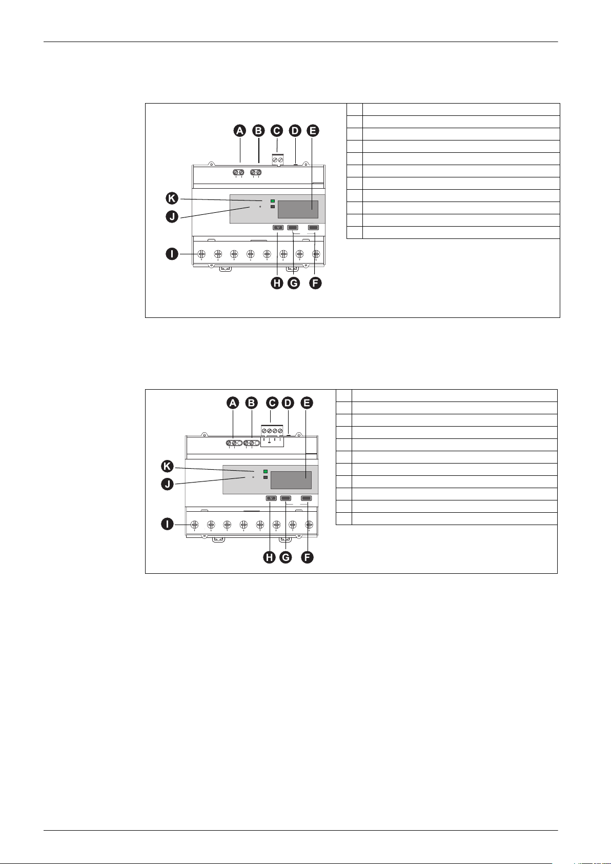
iEM3200 / iEM3210 / iEM3215 - Measurement with CTs
The various features of the listed meters (CTs 1 A or 5 A) are shown in the diagram below:
A Digital inputs for tariff control (iEM3215)
B Display for measurement and configuration
C Pulse out for remote transfer (iEM3210)
D Current inputs (CTs 1 A or 5 A)
C/-
T2
T1
ON
5000 /kWh
OK
(I1) (I2) (I3)
VnV3V2V1
Config
ESC
Reset
S0+ S0-
S2 S1 S1 S2 S1 S2
E Cancel
F Confirm
G Scroll
H Voltage inputs
I Energy pulsing LED (used to verify accuracy)
J Status LED: on/off, error
18 DOCA0005EN-04

iEM3100 / iEM3200 / iEM3300 series user manual Hardware and installation
iEM3235 - Measurement with CTs and M-Bus communications
The various features of the iEM3235 (CTs 1 A or 5 A with M-Bus communications) are shown in the
diagram below:
A Digital input
B Digital output
C Communication port
D Communications LED
M-Bus
C/-
C
DI
DO
ON
5000 /kWh
OK
ESC
Reset
Config
(I1) (I2) (I3)
VnV3V2V1
S2 S1 S1 S2 S1 S2
E Display for measurement and configuration
F Current inputs (CTs 1 A and 5 A)
G Cancel
H Confirm
I Scroll
J Voltage inputs
K Energy pulsing LED (used to verify accuracy)
L Status LED: on/off, error
iEM3250 / iEM3255 / iEM3265 - Measurement with CTs and Modbus or BACnet communications
The various features of the iEM3250 / iEM3255 / iEM3265 (CTs 1 A or 5 A with Modbus or BACnet
communication) are shown in the diagram below:
A Digital input (iEM3255/iEM3265)
B Digital output (iEM3255/iEM3265)
C Communication port
D Communications LED
E Display for measurement and configuration
0V D0/- D1/+
C/-
C
N.C.
DI
N.C.
DO
5000 /kWh
RS485
ON
OK
(I1) (I2) (I3)
VnV3V2V1
Config
ESC
Reset
S2 S1 S1 S2 S1 S2
F Current inputs (CTs 1 A and 5 A)
G Cancel
H Confirm
I Scroll
J Voltage inputs
K Energy pulsing LED (used to verify accuracy)
L Status LED: on/off, error
DOCA0005EN-04 19

Hardware and installation iEM3100 / iEM3200 / iEM3300 series user manual
iEM3275 - Measurement with CTs and LonWorks communications
The various features of the iEM3275 (CTs 1 A or 5 A with LonWorks communications) are shown in
the diagram below:
A Digital input
B Communication port
C Communications / LonWorks operation LED
D Service pin
E Display for measurement and configuration
F Current inputs (CTs 1 A and 5 A)
G Cancel
H Confirm
I Scroll
J Voltage inputs
K Neuron ID
L Energy pulsing LED (used to verify accuracy)
M Status LED: on/off, error
C/-
DI
5000 /kWh
Neuron ID: 000000000000
S/N: 0000000000
LON
ON
OK
(I1) (I2) (I3)
VnV3V2V1
Config
ESC
Reset
S2 S1 S1 S2 S1 S2
iEM3300 / iEM3310 - Direct measurement up to 125 A
The various features of the iEM3300 / iEM3310 are shown in the diagram below:
A Display for measurement and configuration
B Pulse output for remote transfer (iEM3310)
C Cancel
S0+S0-
ON
200 /kWh
OK
ESC
Reset
Config
N’N
L2’
L3’ L3 L2 L1’ L1L1
D Confirm
E Scroll
F Current and voltage inputs (direct measurement up to 125 A)
G Energy pulsing LED (used to verify accuracy)
H Status LED: on/off, error
20 DOCA0005EN-04
iEM3100 / iEM3200 / iEM3300 series user manual Hardware and installation
iEM3335 - Direct measurement up to 125 A and M-Bus communications
The various features of the iEM3335 are shown in the diagram below:
A Digital input
B Digital output
C Communication port
D Communications LED
E Display for measurement and configuration
C/-DIC
DO
ON
200 /kWh
OK
ESC
Reset
Config
N’N
L2’
L3’ L3 L2 L1’ L1L1
F Cancel
G Confirm
H Scroll
I Current and voltage inputs (direct measurement up to 125 A)
J Energy pulsing LED (used to verify accuracy)
K Status LED: on/off, error
iEM3350 / iEM3355 / iEM3365 - Direct measurement up to 125 A and Modbus or BACnet communications
The various features of the iEM3350 / iEM3355 / iEM3365 are shown in the diagram below:
A Digital input (iEM3355 / iEM3365)
B Digital output (iEM3355 / iEM3365)
C Communication port
0V D1/+D0/-
DO
200 /kWh
RS485
ON
OK
ESC
Reset
Config
L2’
L3’ L3 L2 L1’ L1L1
C/-DIC
N’N
D Communications LED
E Display for measurement and configuration
F Cancel
G Confirm
H Scroll
I Current and voltage inputs (direct measurement up to 125 A)
J Energy pulsing LED (used to verify accuracy)
K Status LED: on/off, error
DOCA0005EN-04 21

Hardware and installation iEM3100 / iEM3200 / iEM3300 series user manual
iEM3375 - Direct measurement up to 125 A and LonWorks communications
The various features of the iEM3375 are shown in the diagram below:
A Digital input
B Communication port
C Communications / LonWorks operations LED
D Service pin
E Display for measurement and configuration
F Cancel
G Confirm
H Scroll
I Current and voltage inputs (direct measurement up to 125 A)
J Neuron ID
K Energy pulsing LED (used to verify accuracy)
L Status LED: on/off, error
Neuron ID: 000000000000
S/N:0000000000
N’N
C/-
DI
ON
200 /kWh
Service
OK
ESC
Reset
Config
L2’
L3’ L3 L2 L1’ L1L1
DIN rail mounting and dismounting
HAZARD OF ELECTRIC SHOCK, EXPLOSION, OR ARC FLASH
• Apply appropriate personal protective equipment (PPE) and follow safe electrical work practices.
See NFPA 70E in the USA or applicable local standards.
• This equipment must only be installed and serviced by qualified electrical personnel.
• Turn off all power supplying this device and the equipment in which it is installed before working
on the device or equipment.
• Always use a properly rated voltage sensing device to confirm power is off.
• Replace all devices, doors and covers before turning on power to this equipment.
• Do not exceed the device’s ratings for maximum limits.
Failure to follow these instructions will result in death or serious injury.
Mounting the meter on a DIN rail
1. Position the 2 upper slots on the rear of the meter onto the DIN rail.
DANGER
2. Press the meter against the DIN rail until the locking mechanism engages. The meter is now
attached to the rail. Make sure that the device is not tilted following installation.
22 DOCA0005EN-04

iEM3100 / iEM3200 / iEM3300 series user manual Hardware and installation
Click!
Dismounting the meter from a DIN rail
1. Use a flat-tip screwdriver ( 6.5 mm / 0.25 in) to lower the locking mechanism and release the
meter.
2. Lift the meter out and up to free it from the DIN rail.
DOCA0005EN-04 23

Hardware and installation iEM3100 / iEM3200 / iEM3300 series user manual
Input, output and communications wiring
This section describes the wiring of the digital inputs, digital and pulse outputs and the
communications (as applicable).
DANGER
HAZARD OF ELECTRIC SHOCK, EXPLOSION, OR ARC FLASH
• Apply appropriate personal protective equipment (PPE) and follow safe electrical work practices.
See NFPA 70E in the USA or applicable local standards.
• This equipment must only be installed and serviced by qualified electrical personnel.
• Turn off all power supplying this device and the equipment in which it is installed before working
on the device or equipment.
• Always use a properly rated voltage sensing device to confirm power is off.
• Replace all devices, doors and covers before turning on power to this equipment.
• Do not exceed the device’s ratings for maximum limits.
Failure to follow these instructions will result in death or serious injury.
WARNING
UNINTENDED OPERATION
Do not use the meter for critical control or protection applications where human or equipment safety
relies on the operation of the control circuit.
Failure to follow these instructions can result in death, serious injury or equipment damage.
Related topics
• See “Power system wiring” on page 26 for information on wiring the voltage and current
connections.
Pulse output wiring: iEM3110 / iEM3210 / iEM3310
Rin
5 – 30 V DC
• The pulse output is compatible with S0 format.
• The pulse output can be directly connected to a 24 V DC (< 30 V DC) input on a Zelio or
Twido PLC.
• The pulse output indicates the primary consumption with consideration of transformer ratios.
• For other concentrators, if V DC/Rin > 15 mA, add a resistor Radd = (V DC/0.01) - Rin
Radd
-+
S0+ S0-
Digital input wiring: iEM3115 / iEM3215
11 – 40 V DC
-+
C/- T1
T2
24 DOCA0005EN-04

iEM3100 / iEM3200 / iEM3300 series user manual Hardware and installation
Digital input wiring: iEM3135 / iEM3155 / iEM3165 / iEM3175 / iEM3235 / iEM3255 / iEM3265 / iEM3275 / iEM3335 / iEM3355 / iEM3365 / iEM3375
11 – 40 V DC
-+
C/-
DI
N.C.
• The digital input and output are electrically independent.
Digital output wiring: iEM3135 / iEM3155 / iEM3165 / iEM3235 / iEM3255 / iEM3265 / iEM3335 / iEM3355 / iEM3365
5 – 40 V DC
-
-
/+ +/
Load
C
N.C.
DO
• The programmable digital output is compatible with S0 format when configured as a pulse output.
• The digital output is polarity-independent.
• The digital input and output are electrically independent.
Modbus RS-485 communications wiring: iEM3150 / iEM3155 / iEM3250 / iEM3255 / iEM3350 / iEM3355
0 V
D0 = A’ / Rx-, A / TxD1 = B’ / Rx+, B / Tx+
0V D0/- D1/+
BACnet RS-485 communications wiring: iEM3165 / iEM3265 / iEM3365
0 V
D0 = A’ / Rx-, A / TxD1 = B’ / Rx+, B / Tx+
0V D0/- D1/+
M-Bus communications wiring: iEM3135 / iEM3235 / iEM3335
• The M-Bus communications connection is polarity-independent.
DOCA0005EN-04 25

Hardware and installation iEM3100 / iEM3200 / iEM3300 series user manual
LonWorks communications wiring: iEM3175 / iEM3275 / iEM3375
Service
• The LON communications connection is polarity-independent.
Power system wiring
The diagrams below illustrate how to connect the meters to a single-phase or three-phase 3-wire or
4-wire power system.
DANGER
HAZARD OF ELECTRIC SHOCK, EXPLOSION, OR ARC FLASH
• Apply appropriate personal protective equipment (PPE) and follow safe electrical work practices.
See NFPA 70E in the USA or applicable local standards.
• This equipment must only be installed and serviced by qualified electrical personnel.
• Turn off all power supplying this device and the equipment in which it is installed before working
on the device or equipment.
• Always use a properly rated voltage sensing device to confirm power is off.
• Replace all devices, doors and covers before turning on power to this equipment.
• Do not exceed the device’s ratings for maximum limits.
Failure to follow these instructions will result in death or serious injury.
Voltage input protection
The meter’s voltage inputs must be wired to fuses/breakers and a disconnect switch. If using a voltage
transformer (VT), both primary and secondary sides of the VT must be fused and switched.
• Clearly label the device’s disconnect circuit mechanism and install it within easy reach of the
operator.
• Fuses / circuit breakers must be:
— installed in accordance with all local and national electrical codes and standards, and
— rated for the installation voltage, available fault current, and sized for connected loads.
• Fuse for neutral is required if the source neutral connection is not grounded.
Current input protection for 1 A and 5 A meters
For all connected current inputs on 1 A and 5 A meters with external CTs, use a CT shorting block to
short-circuit the secondary leads of the CTs before removing the current input connections to the
meter.
NOTE: Ground any unused current inputs on 1 A and 5 A meters.
iEM31•• and iEM33•• devices associated with a contactor
Connection requirements for iEM3100 / iEM3110 / iEM3115 / iEM3135 / iEM3150 / iEM3155 /
iEM3165 / iEM3175 / iEM3300 / iEM3310 / iEM3335 / iEM3350 / iEM3355 / iEM3365 / iEM3375:
• When the meter is associated with a contactor, connect the meter upstream of the contactor.
• The meter must be protected by a circuit breaker.
26 DOCA0005EN-04

iEM3100 / iEM3200 / iEM3300 series user manual Hardware and installation
LL
iEM
iEM
Load Load
Related topics
• See “Input, output and communications wiring” on page 24 for information on wiring the digital
inputs, digital or pulse outputs and communications for your device.
63 A direct measurement meter wiring
DANGER
HAZARD OF ELECTRIC SHOCK, EXPLOSION, OR ARC FLASH
• Do not allow the total additive current flowing through the device to exceed 63 A.
Failure to follow these instructions will result in death or serious injury.
Fuses and disconnect switch
Power system Wiring
NN’ L3L2’L2L1’L1 L3’
1PH2W L-N
1PH2W L-L
1PH3W L-L-N
3PH3W
L
N
277 V L-N
NN’ L3L2’L2L1’L1 L3’
L1
L2
480 V L-L
NN’ L3L2’L2L1’L1 L3’
L1
L2
N
277 V L-N
480 V L-L
NN’ L3L2’L2L1’L1 L3’
L1
L2
L3
480 V L-L
NN’ L3L2’L2L1’L1 L3’
L
N
L1
L2
N
277 V L-N
NN’ L3L2’L2L1’L1 L3’
277 V L-N
480 V L-L
NN’ L3L2’L2L1’L1 L3’
L1
L2
L3
N
277 V L-N
480 V L-L
3PH4W
NN’ L3L2’L2L1’L1 L3’
L1
L2
L3
N
277 V L-N
480 V L-L
DOCA0005EN-04 27
Hardware and installation iEM3100 / iEM3200 / iEM3300 series user manual
DANGER
HAZARD OF ELECTRIC SHOCK, EXPLOSION, OR ARC FLASH
• Do not connect N’ to the load when setting the wiring type on the meter to 1PH4W Multi L-N.
Failure to follow these instructions will result in death or serious injury.
Power system Wiring
NN’ L3L2’L2L1’L1 L3’
1PH multiple loads with neutral (1PH4W Multi L-N)
1
The 1PH4W Multi L-N wiring type is only available on the iEM3135, iEM3150, iEM3155, iEM3165 and iEM3175.
1
125 A direct measurement meter wiring
DANGER
HAZARD OF ELECTRIC SHOCK, EXPLOSION, OR ARC FLASH
• Do not allow the total additive current flowing through the device to exceed 125 A.
Failure to follow these instructions will result in death or serious injury.
Fuses and disconnect switch
Power system Wiring
1PH2W L-N
NN’ L3L2’L2L1’L1 L3’
L
N
277 V L-N
NN’ L3L2’L2L1’L1 L3’
L
N
277 V L-N
1PH2W L-L
1PH3W L-L-N
3PH3W
NN’ L3L2’L2L1’L1 L3’
L1
L2
N
277 V L-N
480 V L-L
NN’ L3L2’L2L1’L1 L3’
L1
L2
480 V L-L
NN’ L3L2’L2L1’L1 L3’
L1
L2
N
277 V L-N
480 V L-L
NN’ L3L2’L2L1’L1 L3’
L1
L2
L3
480 V L-L
28 DOCA0005EN-04

iEM3100 / iEM3200 / iEM3300 series user manual Hardware and installation
Power system Wiring
NN’ L3L2’L2L1’L1 L3’
L1
L2
L3
N
277 V L-N
480 V L-L
3PH4W
NN’ L3L2’L2L1’L1 L3’
L1
L2
L3
N
277 V L-N
480 V L-L
DANGER
HAZARD OF ELECTRIC SHOCK, EXPLOSION, OR ARC FLASH
• Do not connect N’ to the load when setting the wiring type on the meter to 1PH4W Multi L-N.
Failure to follow these instructions will result in death or serious injury.
Power system Wiring
NN’ L3L2’L2L1’L1 L3’
1PH multiple loads with neutral (1PH4W Multi L-N)
1
1
The 1PH4W Multi L-N wiring type is only available on the iEM3335, iEM3350, iEM3355, iEM3365 and iEM3375.
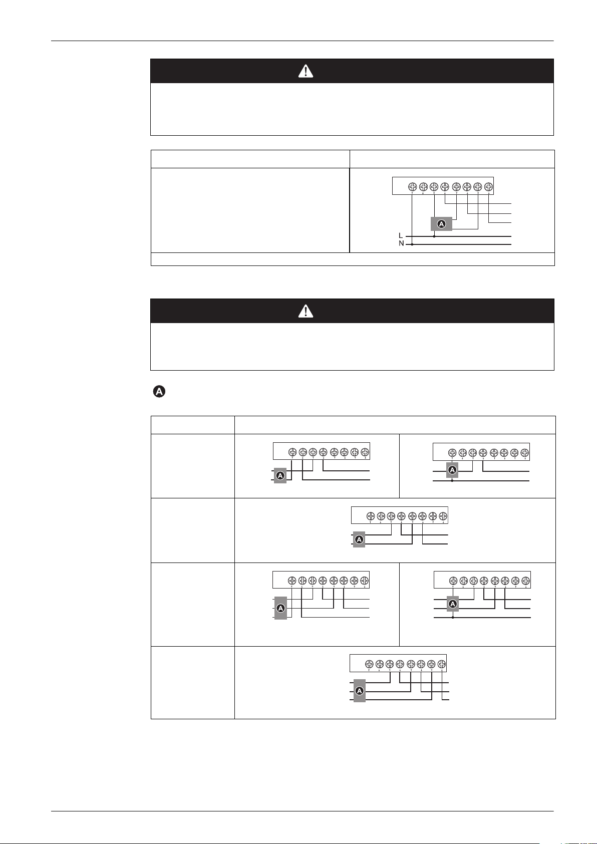
5 A / 1 A meter wiring
DANGER
HAZARD OF ELECTRIC SHOCK, EXPLOSION, OR ARC FLASH
• Never short the secondary of a voltage transformer (VT).
• Never open circuit a current transformer (CT); use the shorting block to short circuit the leads of
the CT before removing the connection from the meter.
• Always use grounded external CTs for current inputs.
Failure to follow these instructions will result in death or serious injury.
Single-phase systems with CTs
250 mA fuses and disconnect switch
Shorting block
Power system Wiring
V1 V2 V3Vn
(I1) (I3)(I2)
1PH2W L-N
S1 S2
277 V L-N
DOCA0005EN-04 29

Hardware and installation iEM3100 / iEM3200 / iEM3300 series user manual
Power system Wiring
1PH2W L-L
1PH3W L-L-N
1PH multiple loads with neutral
(1PH4W Multi L-N)
1
V1 V2 V3Vn
L1
L2
(I1)
S1
S2
480 V L-L
S1
(I1)
S2
S1 S2
V1 V2 V3Vn
L1
L2
N
277 V L-N
480 V L-L
2CTs 3CTs
V1 V2 V3Vn
(I1) (I3)(I2)
(I3)(I2)
(I3)(I2)
V1 V2 V3Vn
(I1) (I3)(I2)
277 V L-N
1
The 1PH4W Multi L-N wiring type is only available on the iEM3235, iEM3250, iEM3255, iEM3265 and iEM3275
Three-phase systems with CTs
250 mA fuses and disconnect switch
Shorting block
indicates wiring for a balanced system
Power system Wiring
1 CT 2CTs 3CTs
V1 V2 V3Vn
3PH3W
480 V L-L
1 CT 2 CTs 3CTs
V1 V2 V3Vn
480 V L-L
277 V L-N
V1 V2 V3Vn
480 V L-L
V1 V2 V3Vn
V1 V2 V3Vn
V1 V2 V3Vn
3PH4W
277 V L-N
277 V L-N
277 V L-N
30 DOCA0005EN-04
 Loading...