


Schneider Electric PM5100 User Manual

PQS
PowerLogic™ PM5100 Series Power and
Energy Meter
User Guide
EAV15105 - EN03
04/2014

Safety Information
Important Information
Read these instructions carefully and look at the equipment to become
familiar with the device before trying to install, operate, service or maintain it.
The following special messages may appear throughout this manual or on
the equipment to warn of potential hazards or to call attention to information
that clarifies or simplifies a procedure .
The addition of either symbol to a “Danger” or “Warning” safety label indicates that
an electrical hazard exists which will result in personal injury if the instructions are
not followed.
This is the safety alert symbol. It is used to alert you to potential personal injury
hazards. Obey all safety messages that follow this symbol to avoid possible injury
or death.
DANGER indicates an imminently hazardous situation which, if not avoided, will
result in death or serious injury.
Please note
WARNING indicates a potentially hazardous situation which, if not avoided, can
result in death or serious injury.
CAUTION indicates a potentially hazardous situation which, if not avoided, can
result in minor or moderate injury.
NOTICE is used to address practices not related to physical injury. The safety
alert symbol shall not be used with this signal word.
Electrical equipment should be installed, operated, serviced and maintained only by
qualified personnel. No responsibility is assumed by Schneider Electric for any
consequences arising out of the use of this material.
A qualified person is one who has skills and knowledge related to the construction,
installation, and operation of electrical equipment and has received safety training
to recognize and avoid the hazards involved.


PowerLogic™ PM5100 series user guide Table of Contents
Chapter 1: Introduction Power and Energy Meter Hardware ................................................................................. 9
Parts and Accessories .................................................................................................. 9
Box Contents ................................................................................................................ 9
Firmware .......................................................................................................................... 9
Chapter 2: Safety Precau-
tions
Chapter 3: Hardware Refer-
ence
Chapter 4: Front panel dis-
play and meter
setup
Before You Begin ........................................................................................................... 11
Notices ........................................................................................................................... 11
Models, Features and Options ....................................................................................... 13
Functions and Characteristics ........................................................................................ 13
Technical Specifications ................................................................................................. 14
Before you begin ............................................................................................................ 16
Safety precautions .......................................................................................................... 16
Dimension ......................................................................................................................17
Meter mounting .............................................................................................................. 17
Mounting the PM5100 ................................................................................................. 18
Meter wiring .................................................................................................................... 19
Recommended cables ................................................................................................ 20
Wiring Diagrams ............................................................................................................. 21
Power system ................................................................................................................. 22
Direct connect voltage limits ....................................................................................... 22
Voltage and current input wiring ................................................................................. 24
Balanced system considerations ................................................................................ 25
Control power wiring ....................................................................................................... 25
Communications ............................................................................................................. 25
Serial communications ................................................................................................ 25
Digital outputs ................................................................................................................. 27
LED indicators ................................................................................................................ 29
Heartbeat / communications LED ............................................................................... 29
Alarm / energy pulsing LED modes ............................................................................ 29
Notification icons ............................................................................................................ 30
Meter screen menus ....................................................................................................... 30
Menu tree .................................................................................................................... 31
Meter setup screen navigation .................................................................................... 32
Front panel meter setup ................................................................................................. 32
Configuring the basic setup parameters ..................................................................... 32
Communications setup ................................................................................................... 34
Setting up serial communications ............................................................................... 34
HMI settings ...................................................................................................................35
Setting up the display .................................................................................................. 35
Setting up regional settings ......................................................................................... 35
Setting up the screen passwords ................................................................................... 36
Lost password ............................................................................................................. 37
Setting the clock ............................................................................................................. 37
Advanced setup .............................................................................................................. 38
Setting up the alarm / energy pulsing LED ..................................................................... 39
Output setup ...................................................................................................................40
Demand setup ................................................................................................................ 40
Alarms setup .................................................................................................................. 41
Remote Meter Setup ...................................................................................................... 41
Chapter 5: Viewing Meter
Data
Viewing meter data from the front panel ........................................................................ 43
Meter data display screens ............................................................................................ 43
Using ION Setup to view or modify configuration data ................................................... 46
Using software to view meter data ................................................................................. 46
Chapter 6: Input / Output Digital output applications ........................................................................................... 47
Digital output setup ..................................................................................................... 47
Alarm / energy pulsing LED setup .................................................................................. 48
© 2014 Schneider Electric All Rights Reserved
5

Table of Contents PowerLogic™ PM5100 series user guide
Chapter 7: Alarms About Alarms ..................................................................................................................51
1-Second Alarms ......................................................................................................... 51
Unary Alarms ...............................................................................................................53
Alarm Priorities ............................................................................................................53
Alarm Setup ...................................................................................................................54
Setting Up 1-Second Alarms .......................................................................................55
Setting Up Unary Alarms .............................................................................................57
Viewing Alarm Activity and History ................................................................................. 57
Viewing Active Alarms and Alarm Counters ................................................................58
Viewing Unacknowledged Alarms and the Alarm History Log .................................... 59
Chapter 8: Measurements
and calculations
Real-time readings ..........................................................................................................61
Energy ............................................................................................................................ 61
Min/max values ............................................................................................................... 61
Power factor ....................................................................................................................61
Power factor min/max convention ...............................................................................62
Power factor sign convention ......................................................................................62
Demand .......................................................................................................................... 63
Power demand calculation methods ...........................................................................63
Current demand ..........................................................................................................65
Predicted demand .......................................................................................................65
Peak demand ..............................................................................................................66
Chapter 9: Power quality Harmonics overview .......................................................................................................67
Total Harmonic Distortion and Total Demand Distortion ............................................. 67
Displaying harmonics data ..............................................................................................68
Viewing harmonics using the front panel .....................................................................68
Viewing TDD ...............................................................................................................69
Viewing THD/thd using the front panel ........................................................................ 69
Chapter 10: Verifying accura-
cy
Testing overview ............................................................................................................. 71
Accuracy test requirements .........................................................................................71
Verifying accuracy test ....................................................................................................73
Energy pulsing considerations ....................................................................................75
Test points ...................................................................................................................76
Typical sources of test errors ......................................................................................76
Chapter 11: Meter resets Front panel meter reset screens ..................................................................................... 77
Global resets ................................................................................................................... 77
Single resets ................................................................................................................... 78
Chapter 12: Maintenance and
Upgrades
Password Recovery ........................................................................................................ 81
Power Meter Memory .....................................................................................................81
Identifying the Firmware Version, Model, and Serial Number ........................................81
Additional Meter Status Information ................................................................................82
Downloading Firmware ...................................................................................................82
Troubleshooting .............................................................................................................. 83
Heartbeat/Comms LED ...............................................................................................83
Getting Technical Support ..............................................................................................84
Register List ....................................................................................................................84
Chapter 13: MID Compliance MID overview ..................................................................................................................85
MID compliance for the meter .........................................................................................85
Specifications relevant to MID ........................................................................................ 85
Safety precautions ..........................................................................................................86
Installation and wiring .....................................................................................................86
Installing the terminal covers ..........................................................................................87
PM5111 default screen ...................................................................................................87
© 2014 Schneider Electric All Rights Reserved6

PowerLogic™ PM5100 series user guide Table of Contents
Meter firmware version ................................................................................................... 88
MID-protected setup parameters .................................................................................... 88
Lock-protected setup parameters ................................................................................... 88
Lock-protected functions ................................................................................................ 88
Setting up the PM5111 ................................................................................................... 89
Basic setup menu ....................................................................................................... 89
Advanced setup menu ................................................................................................ 89
Clock setup menu ....................................................................................................... 89
Passwords setup menu ............................................................................................... 89
Initializing the meter ....................................................................................................... 89
Locking or unlocking the meter ...................................................................................... 89
Setting up lock password ............................................................................................ 90
Glossary Terms ............................................................................................................................. 91
Abbreviations ..................................................................................................................93
© 2014 Schneider Electric All Rights Reserved
7

Table of Contents PowerLogic™ PM5100 series user guide
© 2014 Schneider Electric All Rights Reserved8
PowerLogic™ PM5100 user guide Chapter 1—Introduction
Chapter 1—Introduction
This user guide explains how to operate and configure a PowerLogic™ PM5100 Series
Power and Energy Meter.
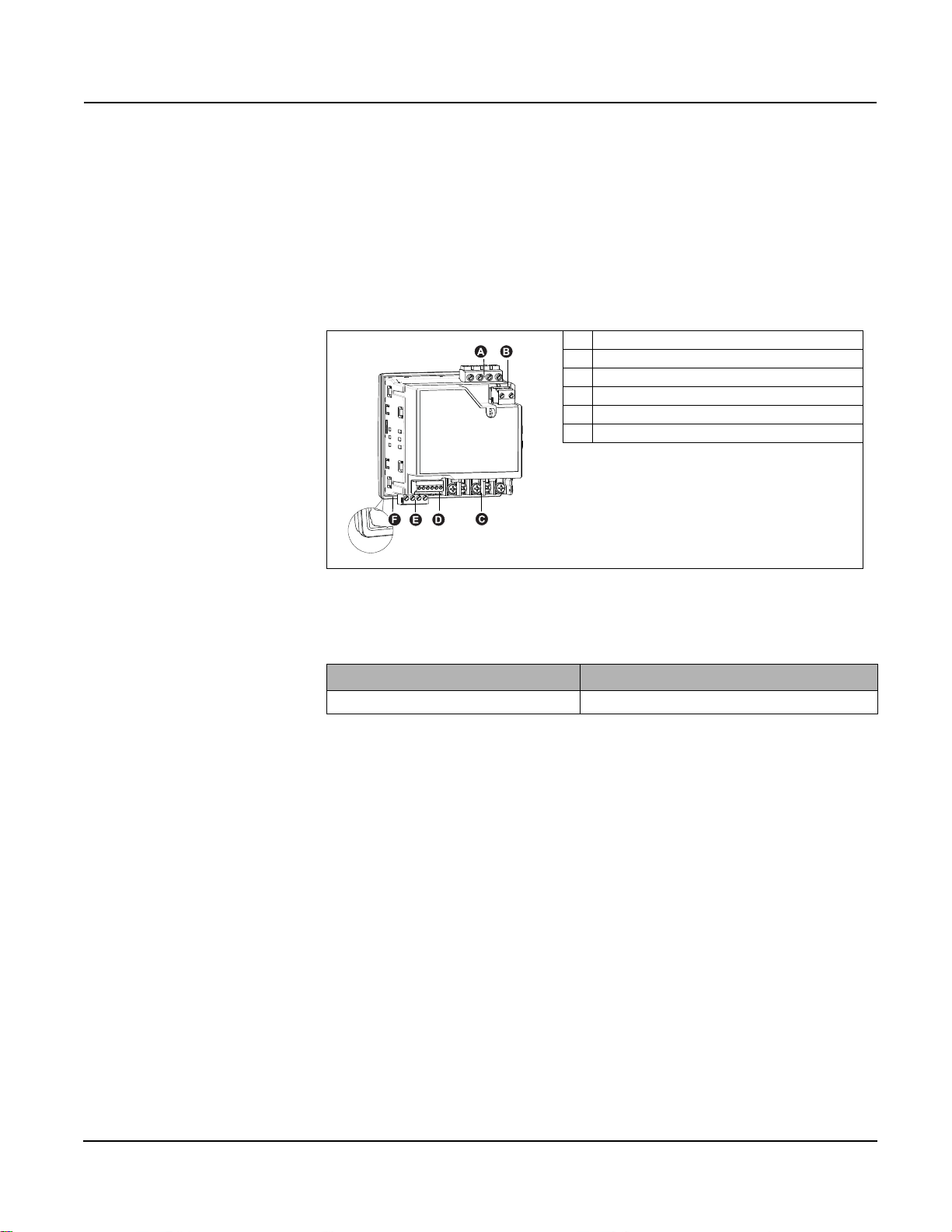
Power and Energy Meter Hardware
Parts of the meter (rear view)
A Voltage inputs
B Control power
C Current inputs
D Digital output
E Communications port - RS-485(optional)
FGasket
Parts and Accessories
Box Contents
Firmware
Table 1– 1 Meter Models
Description Model Numbers
Power and Energy meter with Integrated Display
PowerLogic
TM
PM5100, PM5110, and PM5111
1. Power and Energy Meter (1)
2. Installation Guide (1)
3. Calibration Certificate (1)
4. Connectors
5. Retainer Clips (2)
This user guide is written to be used with firmware version 01.00.0 and higher. See
“Identifying the Firmware Version, Model, and Serial Number” on page 81 for instructions
on determining the firmware version.
© 2014 Schneider Electric All Rights Reserved
9

Chapter 1—Introduction PowerLogic™ PM5100 user guide
© 2014 Schneider Electric All Rights Reserved10

PowerLogic™ PM5100 series user guide Chapter 2—Safety Precautions
Chapter 2—Safety Precautions
Before You Begin
Installation, wiring, testing and service must be performed in accordance with all local and
national electrical codes.
This section contains important safety precautions that must be followed before
attempting to install, service, or maintain electrical equipment. Carefully read and follow
the safety precautions outlined below.
HAZARD OF ELECTRIC SHOCK, EXPLOSION, OR ARC FLASH
• Apply appropriate personal protective equipment (PPE) and follow safe electrical
work practices. In the USA, see NFPA 70E or CSAZ462.
• Only qualified electrical workers should install this equipment. Such work should be
performed only after reading this entire set of instructions.
• If the equipment is not used in a manner specified by the manufacturer, the protection
provided by the equipment may be impaired.
• NEVER work alone.
• Before performing visual inspections, tests, or maintenance on this equipment,
disconnect all sources of electric power. Assume that all circuits are live until they
have been completely de-energized, tested, and tagged. Pay particular attention to
the design of the power system. Consider all sources of power, including the
possibility of back feeding.
• Turn off all power supplying the meter and the equipment in which it is installed before
working on it.
• Always use a properly rated voltage sensing device to confirm that all power is off.
• Before closing all covers and doors, inspect the work area for tools and objects that
may have been left inside the equipment.
• When removing or installing panels, do not allow them to extend into the energized
bus.
• The successful operation of this equipment depends upon proper handling,
installation, and operation. Neglecting fundamental installation requirements may
lead to personal injury as well as damage to electrical equipment or other property.
• Before performing Dielectric (Hi-Pot) or Megger testing on any equipment in which the
energy meter is installed, disconnect all input and output wires to the energy meter.
High voltage testing may damage electronic components contained in the meter.
• This equipment should be installed in a suitable electrical enclosure.
Failure to follow these instructions will result in death or serious injury.
Notices
FCC PART 15 NOTICE This equipment has been tested and found to comply with the limits for a Class B digital
device, pursuant to part 15 of the FCC Rules. These limits are designed to provide
reasonable protection against harmful interference in a residential installation. This
equipment generates, uses, and can radiate radio frequency energy and, if not installed
and used in accordance with the instructions, may cause harmful interference to radio
communications. However, there is no guarantee that interference will not occur in a
particular installation. If this equipment does cause harmful interference to radio or
television reception, which can be determined by turning the equipment off and on, the
user is encouraged to try to correct the interference by one or more of the following
measures:
• Reorient or relocate the receiving antenna.
© 2014 Schneider Electric All Rights Reserved
11

PowerLogic™ PM5100 series user guide Chapter 2—Safety Precautions
• Increase the separation between the equipment and receiver.
• Connect the equipment to an outlet on a circuit different from that to which the receiver
is connected.
• Consult the dealer or an experienced radio/TV technician for help.
This Class B digital apparatus complies with Canadian ICES-003.
© 2014 Schneider Electric All Rights Reserved12
PowerLogic™ PM5100 series user guide Chapter 3—Hardware Reference
Chapter 3—Hardware Reference
This section supplements the meter’s installation sheet and provides additional
information about the meter’s physical characteristics and capabilities.
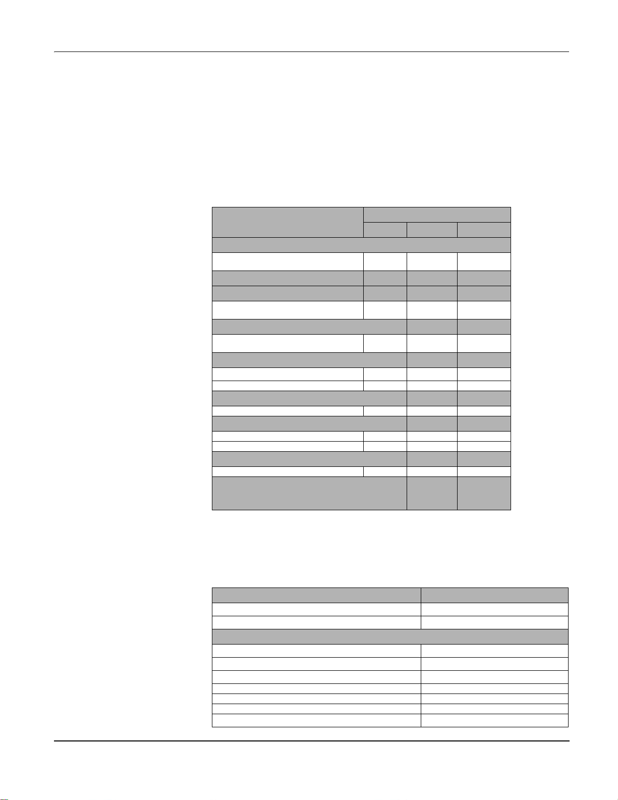
Models, Features and Options
Table 3 –1: PM5100 Series - Models, Features and Options
Features and Options
Installation
Fast installation, panel mount with integrated
display
Accuracy Cl 0.5S Cl 0.5S Cl 0.5S
Display
Backlit LCD, multilingual, bar graphs, 6 lines, 4
concurrent values
Power and energy metering
3-phase voltage, current, power, demand,
energy, frequency, power factor
Power quality analysis
THD, thd, TDD
Harmonics, individual (odd) up to 15th 15th 15th
I/Os
Digital output 1DO 1DO 1DO
Alarms and control
Alarms 33 33 33
Set point response time, seconds 1 1 1
Communications
Serial ports with modbus protocol 0 1 1
MID ready compliance,
EN50470-1/3, Annex B and Annex D
Class C
PM5100 PM5110 PM5111
PM5100 series
Functions and Characteristics
Table 3 –2: Functions and Characteristics
General PM5100 Series
Use on LV and MV systems
Basic metering with THD and min/max readings
Instantaneous rms values
Current (per phase and neutral)
Voltage (total, per phase L-L and L-N)
Frequency
Real, reactive, and apparent power (Total and per phase) Signed, Four Quadrant
True Power Factor (Total and per phase) Signed, Four Quadrant
Displacement PF (Total and per phase) Signed, Four Quadrant
% Unbalanced I, V L-N, V L-L
© 2014 Schneider Electric All Rights Reserved 13

PowerLogic™ PM5100 series user guide Chapter 3—Hardware Reference
Energy Values*
Accumulated Active, Reactive and Apparent Energy Received/Delivered; Net and absolute
Demand Values*
Current average
Active power
Reactive power
Apparent power
Demand calculation (Sliding, fixed and rolling block, thermal
methods)
Synchronization of the measurement window to input,
communication command or internal clock
Settable Demand intervals
Present, Last, Predicted, Peak, and Peak
Date Time
Present, Last, Predicted, Peak, and Peak
Date Time
Present, Last, Predicted, Peak, and Peak
Date Time
Present, Last, Predicted, Peak, and Peak
Date Time
Other Measurements*
Operating timer
Load timer
Alarm counters and alarm logs
Power Quality Measurements
THD, thd (Total Harmonic Distortion) I, V L-N, V L-L per phase I, V L-N, V L-L
TDD (Total Demand Distortion)
Individual harmonics (odds) 15th
Data Recording
Min/max of instantaneous values, plus phase identification*
Alarms with 1s timestamp*
Min/max log
I/Os
Digital output
Timestamp resolution in seconds 1
1
(kWh only)
Technical Specifications
NOTE: *Stored in non-volatile memory
Electrical Characteristics
Type of measurement: True rms on three-phase
(3P, 3P + N), zero blind
Measurement accuracy
IEC 61557-12
Active Energy
Reactive Energy
Active Power Class 0.5 as per IEC 61557-12
Reactive Power Class 2 as per IEC 61557-12
Apparent Power Class 0.5 as per IEC 61557-12
Current, Phase Class 0.5 as per IEC 61557-12
Voltage, L-N Class 0.5 as per IEC 61557-12
Frequency Class 0.05 as per IEC 61557-12
1
2
2
64 samples per cycle
PMD/[SD|SS]/K70/0.5
Class 0.5S as per IEC 62053-22
Class 2S as per IEC 62053-23
© 2014 Schneider Electric All Rights Reserved14
1
1
1
1
1
1

PowerLogic™ PM5100 series user guide Chapter 3—Hardware Reference
Power Factor Class 0.5 as per IEC 61557-12
Voltage Harmonics Class 5 as per IEC 61557-12
Voltage THD/thd Class 5 as per IEC 61557-12
Current Harmonics Class 5 as per IEC 61557-12
Current THD/thd Class 5 as per IEC 61557-12
1
1
1
1
1
MID Directive (2004/22/EC) Annex B and Annex D (PM5111) Class C
Input-voltage (up to 1.0 MV AC max, with voltage transformer)
UL: 20-347 V L-N/35-600 V L-L
Nominal Measured Voltage range
IEC: 20-400 V L-N/35-690 V L-L
(absolute range 35 V L-L to 760 V L-L)
Impedance 5 M Ω
F nom 50/60 Hz
Input-current (configurable for 1 or 5 A secondary CTs)
I nom 5 A
Measured Amps with over range and Crest Factor
Starting current: 5mA
Operating range: 50mA to 8.5A
Withstand Continuous 20 A,10s/hr 50 A, 1s/hr 500 A
Impedance < 0.3 m Ω
F nom 50/60 Hz
Burden <0.026VA at 8.5A
Frequency measurement
Measurement range 45 to 65 Hz
AC control power
Operating range
100 - 277 V AC L-N / 415 V L-L +/-10%
CAT III 300V class per IEC 61010
Burden <5 W,11 VA at 415 V L-L
Frequency 45 to 65 Hz
80 mS typical at 120V AC and maximum burden.
Ride-through time
100 mS typical at 230 V AC and maximum burden
100 mS typical at 415 V AC and maximum burden
DC control power
Operating range 125-250 V DC ±20%
Burden <4 W at 250 V DC
Ride-through time 50 mS typical at 125 V DC and maximum burden
Outputs
Digital output
Max load voltage 40 V DC
Max load current 20 mA
On Resistance 50 Ω max
Meter constant
from 1 to 9,999,999 pulses per k_h (k_h = kWh,
kVARh or kVAh depending on the energy parameter
selected)
Pulse width for Digital Output 50% duty cycle
Pulse frequency for Digital Output 25 Hz max.
Leakage current 0.03 micro Amps
Isolation 5 kV rms
Optical outputs
Pulse width (LED) 200
s
Pulse frequency 50 Hz. max.
Meter constant from 1 to 9,999,999 pulses per k_h
Mechanical Characteristics
Product weight 380 g
IP degree of protection (IEC 60529) IP52 front display, IP30 meter body
Dimensions W x H x D [protrusion from cabinet]
96 x 96 x 72mm (depth of meter from housing
mounting flange) [13mm]
Mounting position Vertical
Panel thickness 6 mm maximum
Environmental Characteristics
Operating temperature
Meter -25 °C to +70 °C
Display (Display functions to -25º with reduced
performance)
Storage temp. -40 °C to +85 °C
Humidity range 5 to 95% RH at 50 °C (non-condensing)
-25 °C to +70 °C
© 2014 Schneider Electric All Rights Reserved 15

PowerLogic™ PM5100 series user guide Chapter 3—Hardware Reference
Pollution degree 2
Altitude 2000 m CAT III / 3000 m CAT II
For indoor use only
Electromagnetic Compatibility
Electrostatic discharge IEC 61000-4-2
Immunity to radiated fields IEC 61000-4-3
Immunity to fast transients IEC 61000-4-4
Immunity to surge IEC 61000-4-5
Conducted immunity 150kHz to 80MHz IEC 61000-4-6
Immunity to magnetic fields IEC 61000-4-8
Immunity to voltage dips IEC 61000-4-11
Radiated emissions FCC part 15, EN 55022 Class B
Conducted emissions FCC part 15, EN 55022 Class B
3
Safety
Europe
U.S. and Canada
Measurement category (Voltage and Current inputs) CAT III up to 400 V L-N / 690 V L-L
Dielectric As per IEC/UL 61010-1 (3rd Edition)
Protective Class II, Double insulated for user accessible parts
CE, as per IEC 61010-1 (3rd Edition), IEC 62052-11
& IEC61557-12
cULus as per UL61010-1 (3rd Edition)
CAN/CSA-C22.2 No. 61010-1 (3rd Edition)
1
Communication
RS-485 port Modbus RTU, Modbus ASCII (7 or 8 bit),
JBUS
Firmware and language file update Meter firmware update via the communication ports
Isolation 2.5 kVrms, double insulated
2-Wire, 9600,19200 or 38400 baud, Parity - Even,
Odd, None, 1 stop bit if parity Odd or Even, 2 stop
bits if None; (Optional)
Human Machine Interface
Display type Monochrome Graphics LCD
Resolution 128 x 128
Backlight White LED
Viewable area (W x H) 67 x 62.5 mm
Keypad 4-button
Indicator Heartbeat / Comm activity Green LED
Energy pulse output / Active alarm indication (configurable) Optical, amber LED
Wavelength 590 to 635 nm
Maximum pulse rate 2.5 kHz
Before you begin
Safety precautions
1
For firmware version 1.1.1 and higher
2
For 1A nominal CT when I > 0.15A
3
Tests are conducted as per IEC 61557-12 (IEC 61326-1), 62052-11 and EN50470
Carefully read and follow the safety precautions before working with the meter.
Installation, wiring, testing and service must be performed in accordance with all local and
national electrical codes.
© 2014 Schneider Electric All Rights Reserved16
PowerLogic™ PM5100 series user guide Chapter 3—Hardware Reference
DANGER
90.00°
90.00°
96.00mm
96.00
mm
78.5 mm
12.8 mm
107.4
mm
90.6
mm
72.00 mm
HAZARD OF ELECTRIC SHOCK, EXPLOSION OR ARC FLASH
• Apply appropriate personal protective equipment (PPE) and follow safe electrical
work practices. See NFPA 70E in the USA or applicable local standards.
• Turn off all power supplying this device before working on it.
• Always use a properly rated voltage sensing device to confirm that all power is off.
• Do not exceed the device’s ratings for maximum limits.
• Always use grounded external CTs for current inputs.
Failure to follow these instructions will result in death or serious injury.
1. Turn off all power supplying this device before working on it.
2. Always use a properly rated voltage sensing device to confirm that all power is off.
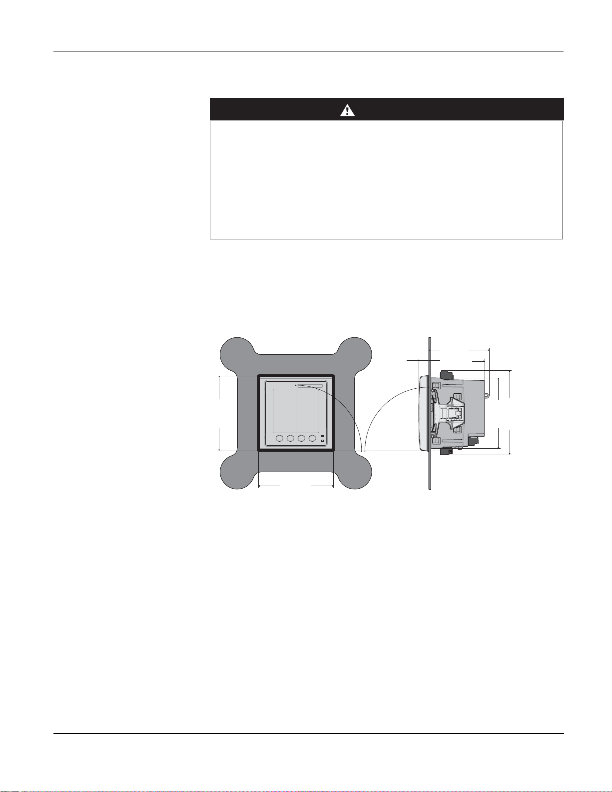
Dimension
Figure 3–1: Dimension
Meter mounting
This section describes how to mount the meter.
© 2014 Schneider Electric All Rights Reserved 17
PowerLogic™ PM5100 series user guide Chapter 3—Hardware Reference
92.0
mm
+0.8
-
0.0
92.0
mm
+0.8
-
0.0
CLICK
CLIC
K
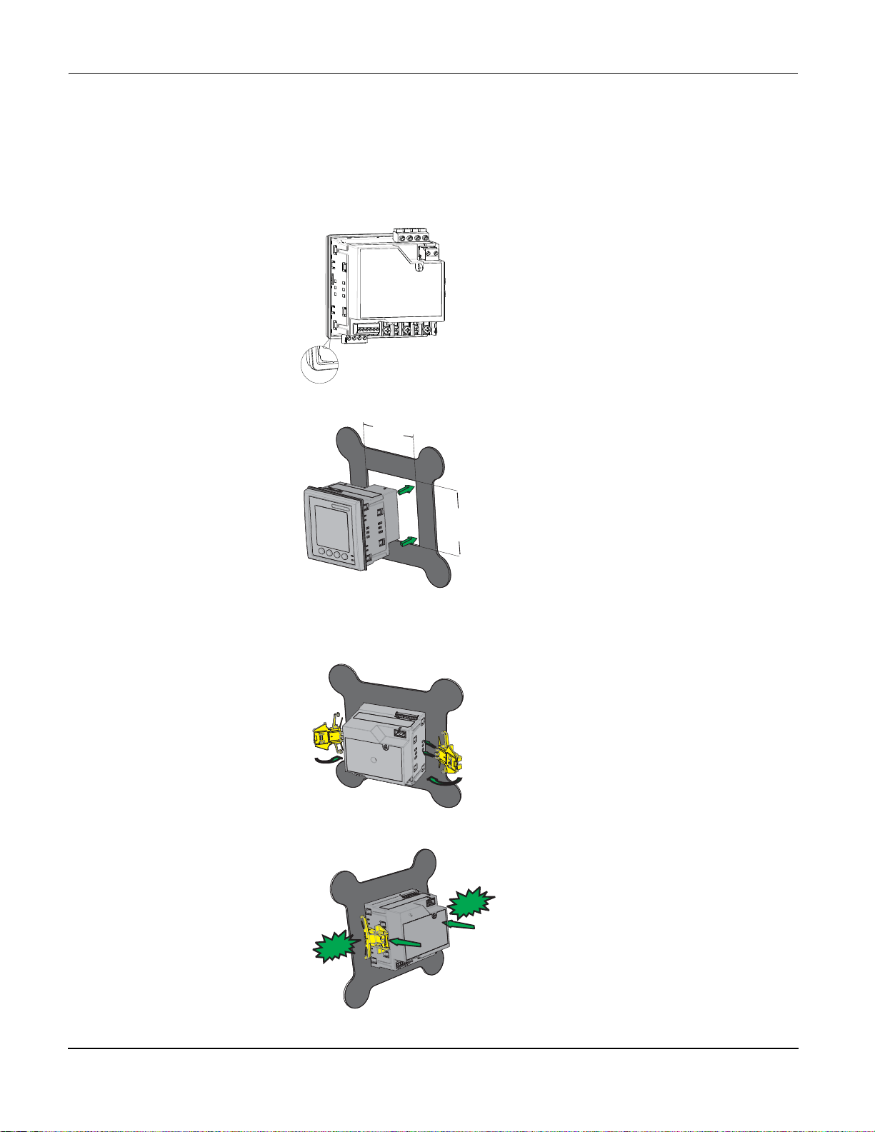
Mounting the PM5100
The meter is designed to be mounted inside a 1/4-DIN panel cutout.
1. Inspect the gasket (installed around the perimeter of the front display) and make sure
it is secured properly and not damaged.
2. Insert the meter through the mounting hole.
3. Line up the tabs of the retainer clips with the slots on either side of the meter. While
holding the retainers at a slight angle, push the retainers in and forward to position
them in place. In situations where the spacing between meters is tight, use a flat-head
screwdriver with a long, narrow shaft to help secure the clips.
4. Push the middle of the clip assembly to lock the retainer in place and secure the
meter.
© 2014 Schneider Electric All Rights Reserved18
PowerLogic™ PM5100 series user guide Chapter 3—Hardware Reference
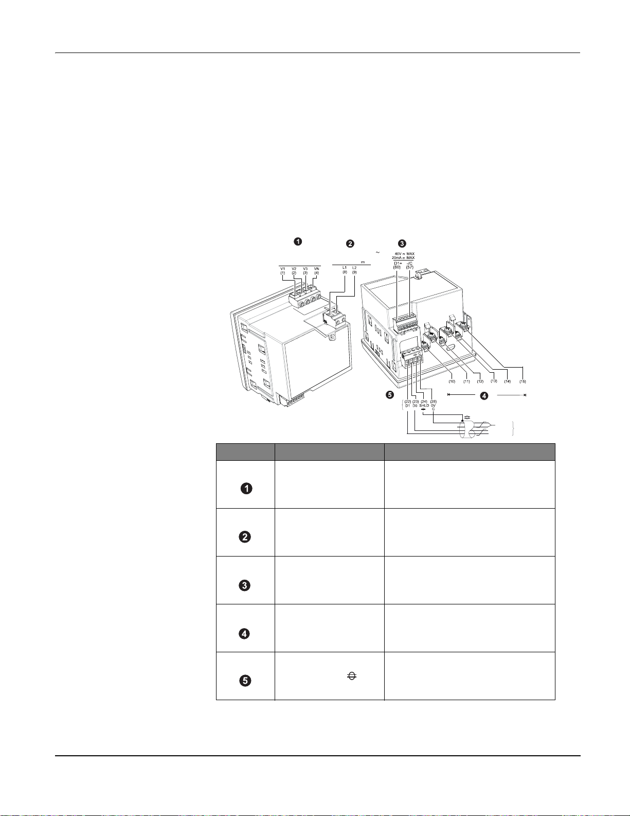
Meter wiring
For wiring instructions and safety precautions, see the meter installation sheet that was
shipped with your meter, or download a copy at www.schneider-electric.com.
• Wire connections to the meter’s voltage inputs, control power, digital output, and RS-
485 communications are terminated using the supplied pluggable wire connectors.
• When wiring the meter’s current inputs, terminate the wire ends with ring or split-ring
crimp connectors.
Use the meter installation sheet when wiring the meter.
UL: CAT III
20-347VLN/35-600VLL
IEC: CAT III
20-400VLN/35-690VLL
9/19//s
s+]9$
9s:
_
+
Modbus
RS-485
_
+
Serial No. Description Specification
• Wire size: 0.82 - 3.31 mm
Voltage Inputs (V1, V2, V3, VN)
Control Power (L1, L2)
Digital Output (D1+, -/C)
Current Inputs
, I1-, I2+, I2-, I3+, I3-)
(I
1+
Modbus RS-485 (+,-, , C)
• Wire strip length: 0.28 in (7 mm)
• Torque: 0.5 - 0.6 N·m (4.4 - 5.3 in·lb)
• Screw driver type: M3
• Wire size: 0.82 - 3.31 mm
• Wire strip length: 0.28 in (7 mm)
• Torque: 0.5 - 0.6 N·m (4.4 - 5.3 in·lb)
• Screw driver type: M3
• Wire size: 0.33 - 3.31 mm
• Wire strip length: 0.24 in (6 mm)
• Torque: 0.5 - 0.6 N·m (4.4 - 5.3 in·lb)
• Screw driver type: M2
• Wire size: 0.82 - 3.31 mm
• Wire strip length:0.28 in (7 mm)
• Torque: 0.9 - 1.0 N·m (8.0 - 9.0 in·lb)
• Screw driver type: PH1
• Wire size: 0.33 - 3.31 mm
• Wire strip length: 0.24 in (6 mm)
• Torque: 0.5 - 0.6 N·m (4.4 - 5.3 in·lb)
• Screw driver type: M3
I
I
I
1+
2+
1-
$$120$
2
2
2
2
2
I
I
I
2-
3+
3-
0V
Modbus
RS-485
D0 = Rx-, TxD1 = Rx+,Tx+
(18 - 12 AWG)
(18 - 12 AWG)
(22 - 12 AWG)
(18 - 12 AWG)
(22 - 12 AWG)
© 2014 Schneider Electric All Rights Reserved 19

PowerLogic™ PM5100 series user guide Chapter 3—Hardware Reference
Recommended cables
Communication Make Part code Description
RS-485 Belden
3105A Multi-Conductor - EIA Industrial RS-485 PLTC/CM
3106A Multi-Conductor - EIA Industrial RS-485 PLTC/CM
© 2014 Schneider Electric All Rights Reserved20
PowerLogic™ PM5100 series user guide Chapter 3—Hardware Reference
B
A
+
-
+
-
+
-
+
L
B
A
(I1) (I2) (I3)
V1 V2 V3VN
+
-
+
-
+
-
+
A
B
+
-
+
-
+
-
+
B
A
+
-
+
-
+
-
+
A
B
+
-
+
-
+
-
+
B
A
+-+-+
-
+
+
L
B
A
(I1) (I2) (
V1 V2 V3VN
+
-
+
-
+
+
A B
+-+-+
-
+
+
+
B
A
+
-
+
-
+
-
+
L1
L2
L3
A B
V1 V2 V3VN
(I1) (I2) (I3)
+-+-+
-
+
+
A B
+-+-+
-
+
C
A
B
+-+-+
-
+
+
+
C
A
B
+-+-+
-
+
+
C
L1
A
V1 V2 V3VN
B
(I1) (I2) (I3)
+-+-+
-
+
C
L1
L2
L3
A
V1 V2 V3VN
B
(I1) (I2) (I3)
+
+
-
+-+
-
L1
L2
L3
N
A
B
V1 V2 V3VN
(I1) (I2) (I3)
+-+-+
-
+
+
+
L1
L2
L3
N
B
V1 V2 V3VN
(I1) (I2) (I3)
A
+-+-+
-
+
L1
L2
L3
N
A
C
V1 V2 V3VN
B
(I1) (I2) (I3)
+
+
+
+
-
+-+
-
L1
L2
L3
N
A
C
V1 V2 V3VNB(I1) (I2) (I3)
+-+-+
-
+
+
L1
L2
L3
N
A
C
V1 V2 V3VN
B
(I1) (I2) (I3)
+-+-+
-
+
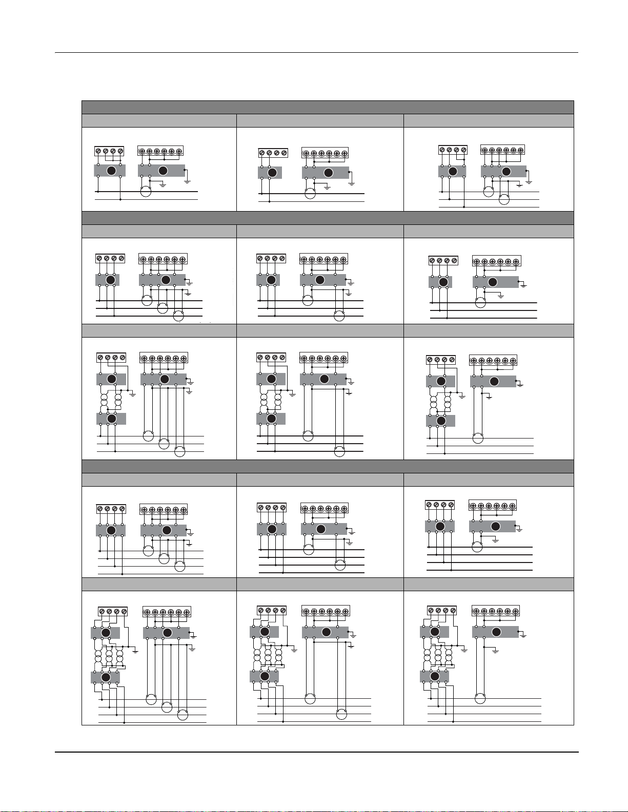
Wiring Diagrams
1PH
1PH2WLN 1PH2WLL 1PH3WLL with N
V1 V2 V3VN
L
N
(I1) (I2) (I3)
3PH3W
3CT 2CT 1CT *
V1 V2 V3VN (I1) (I2) (I3)
L1
L2
L3
2VT, 3CT 2VT, 2CT 2VT, 1CT *
V1 V2 V3VN
L1
L2
L3
(I1) (I2) (I3)
3PH4W
3CT 2CT * 1CT *
V1 V2 V3VN
L1
L2
V1 V2 V3VN
L
N
V1 V2 V3VN
L1
L2
L3
(I1) (I2) (I3)
(I1) (I2) (I3)
(I1) (I2) (I3)
V1 V2 V3VN
V1 V2 V3VN
V1 V2 V3VN
L1
L1
L2
L
L2
N
N
V1 V2 V3VN (I1) (I2) (I3)
L1
L2
L3
(I1) (I2) (I3)
(I1) (I2) (I3)
(I1) (I2) (I3)
© 2014 Schneider Electric All Rights Reserved 21
V1 V2 V3VN
L1
L2
L3
N
A
(I1) (I2) (I3)
+-+-+
B
+
-
+
3VT, 3CT 3VT, 2CT * 3VT, 1CT *
NOTE: According to Blondel's theorem, in an N wire system a minimum of N-1 measuring elements are required for correct measurement.
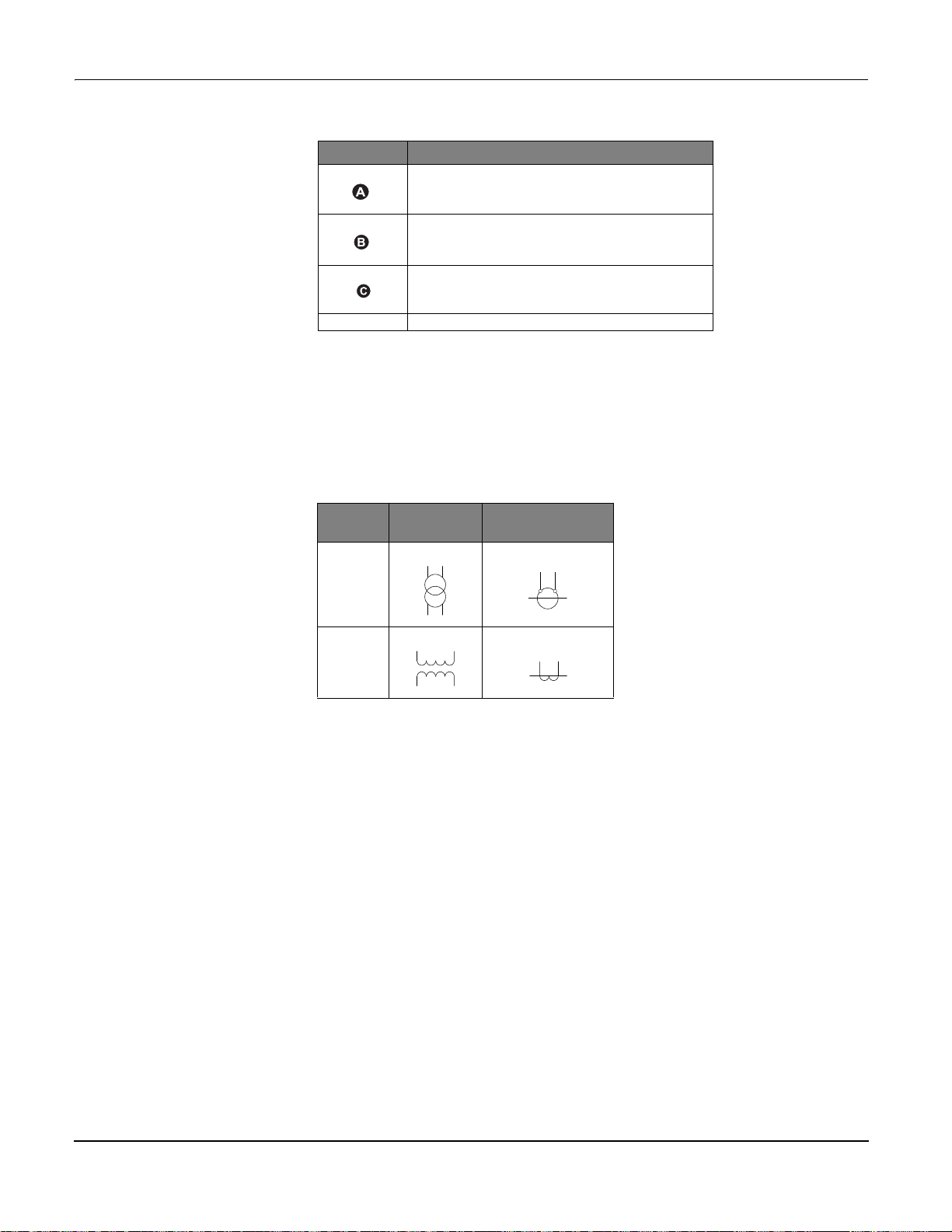
PowerLogic™ PM5100 series user guide Chapter 3—Hardware Reference
Symbol Description
500 mA fused disconnect / circuit breaker (not supplied)
Shorting block (not supplied)
PT primary fuses and disconnect switch (not supplied)
*
Indicates wiring for a balanced system
NOTE:
• Clearly label the device’s disconnect circuit mechanism and install it within easy reach
of the operator.
• The fuses / circuit breakers must be rated for the installation voltage and sized for the
available fault current.
• Fuse for neutral terminal is required if the source neutral connection is not grounded.
Potential
Transformer
IEC
ANSI
Current Transformer
Power system
Direct connect voltage limits
This section outlines typical requirements for wiring the voltage and current inputs of the
meter to the electrical power system.
For wiring instructions and safety precautions, see the meter installation sheet that was
shipped with your meter, or download a copy at www.schneider-electric.com.
You can connect the meter’s voltage inputs directly to the phase voltage lines of the
power system if the power system’s line-to-line or line-to-neutral voltages do not exceed
the meter’s direct connect maximum voltage limits. The meter's voltage measurement
inputs are rated by the manufacturer for up to 400 V L-N / 690 V L-L. However, the
maximum voltage allowed for direct connection may be lower, depending on the local
electrical codes and regulations. In US and Canada the maximum voltage on the meter
voltage measurement inputs may not exceed 347 V L-N / 600 V L-L.
If your system voltage is greater than the specified direct connect maximum voltage, you
must use VTs (voltage transformers) to step down the voltages.
© 2014 Schneider Electric All Rights Reserved22
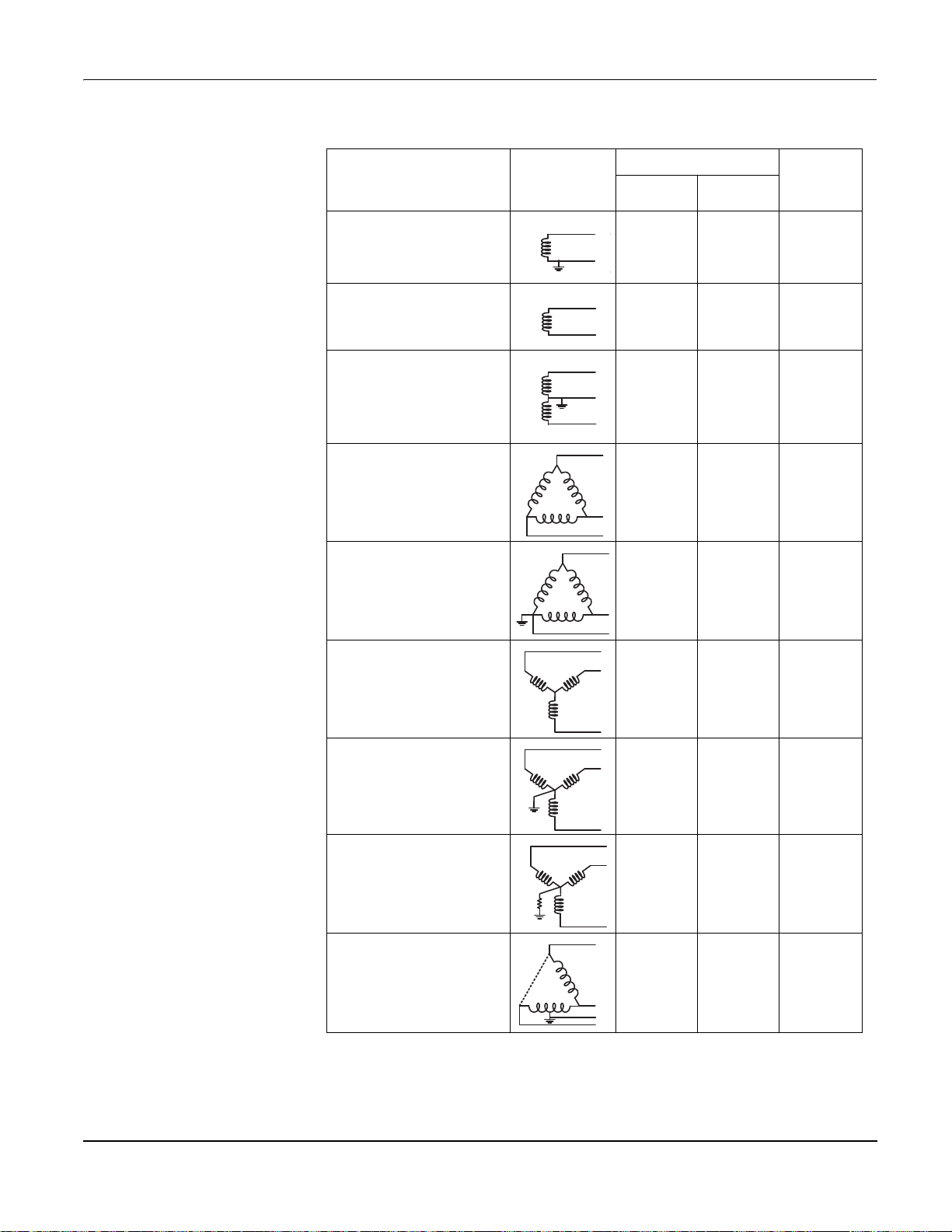
PowerLogic™ PM5100 series user guide Chapter 3—Hardware Reference
N
Power system setup parameters
Power system description
—
Meter setting
Single-phase 2-wire line-to-neutral
—
1PH2W LN
Single-phase 2-wire line-to-line
—
1PH2W LL
Single-phase 3-wire line-to-line with
neutral
—
1PH3W LL with N
3-phase 3-wire Delta ungrounded
—
3PH3W Dlt Ungnd
3-phase 3-wire Delta corner
grounded
—
3PH3W Dlt Crnr Gnd
Symbol
Direct connect maximum
UL IEC
347 V L-N 400 V L-N 1 VT
600 V L-L 600 V L-L 1VT
347 V L-N /
600 V L-L
600 V L-L 600 V L-L 2 VT
600 V L-L 600 V L-L 2 VT
400 V L-N /
690 V L-L
# of VTs
(if required)
2VT
3-phase 3-wire Wye ungrounded
—
3PH3W Wye Ungnd
3-phase 3-wire Wye grounded
—
3PH3W Wye Gnd
3-phase 3-wire Wye resistancegrounded
—
3PH3W Wye Res Gnd
3-phase 4-wire open Delta centertapped
—
3PH4W Opn Dlt Ctr Tp
600 V L-L 600 V L-L 2 VT
600 V L-L 600 V L-L 2 VT
600 V L-L 600 V L-L 2 VT
240 V L-N /
415 V L-N /
480 V L-L
240 V L-N /
415 V L-N /
480 V L-L
3 VT
© 2014 Schneider Electric All Rights Reserved 23

PowerLogic™ PM5100 series user guide Chapter 3—Hardware Reference
N
N
N
Power system setup parameters (continued)
Power system description
—
Meter setting
3-phase 4-wire Delta center-tapped
—
3PH4W Dlt Ctr Tp
3-phase 4-wire ungrounded Wye
—
3PH4W Wye Ungnd
3-phase 4-wire grounded Wye
—
3PH4W Wye Gnd
3-phase 4-wire resistance-grounded
Wye
—
3PH4W Wye Res Gnd
Symbol
Direct connect maximum
UL IEC
240 V L-N /
415 V L-N /
480 V L-L
347 V L-N /
600 V L-L
347 V L-N /
600 V L-L
347 V L-N /
600 V L-L
240 V L-N /
415 V L-N /
480 V L-L
347 V L-N /
600 V L-L
400 V L-N /
690 V L-L
347 V L-N /
600 V L-L
# of VTs
(if required)
3 VT
3 VT or 2 VT
3 VT or 2 VT
3 VT or 2 VT
Voltage and current input wiring
For wiring instructions and safety precautions, see the meter installation sheet that was
shipped with your meter, or download a copy at www.schneider-electric.com.
Voltage input protection
The meter’s voltage inputs must be wired to fuses/breakers and a disconnect switch. If
using a voltage transformer (VT), both primary and secondary sides of the VT must be
wired to fuses/breakers and disconnect switches.
• Clearly label the device’s disconnect circuit mechanism and install it within easy reach
of the operator.
• The fuses / circuit breakers must be rated for the installation voltage and sized for the
available fault current.
• Fuse for neutral terminal is required if the source neutral connection is not grounded.
See the meter installation sheet for fuse ratings.
Current input protection
For all connected current inputs, use a CT shorting block to short-circuit the secondary
leads of the CTs before removing the current input connections to the meter.
NOTE: Ground any unused current inputs.
© 2014 Schneider Electric All Rights Reserved24

PowerLogic™ PM5100 series user guide Chapter 3—Hardware Reference
Balanced system considerations
In situations where you are monitoring a balanced 3-phase load, you may choose to
connect only one or two CTs on the phase(s) you want to measure, and then configure
the meter so it calculates the current on the unconnected current input(s).
NOTE: For a balanced 4-wire Wye system, the meter’s calculations assume that there is
no current flowing through the neutral conductor.
Balanced 3-phase Wye system with 2 CTs
The current for the unconnected current input is calculated so that the vector sum for all
three phase currents equal zero.
Balanced 3-phase Wye or Delta system with 1 CT
The currents for the unconnected current inputs are calculated so that their magnitude
and phase angle are identical and equally distributed, and the vector sum for all three
phase currents equal zero.
NOTE: You must always use 3 CTs for 3-phase 4-wire center-tapped Delta or
center-tapped open Delta systems.
Control power wiring
Communications
Serial communications
For wiring instructions and safety precautions, see the meter installation sheet that was
shipped with your meter, or download a copy at www.schneider-electric.com.
The meter can be powered from an AC or DC power source.
• L1 and L2 are non-polarized. If using an AC power supply with neutral, connect
neutral to the meter’s L2 terminal.
• Always use a fuse on L1. Fuse L2 when connecting an ungrounded neutral to the
control power.
• If using a control power transformer, fuse both primary and secondary sides of the
transformer.
• The fuses / circuit breakers must be rated for the installation voltage and sized for the
available fault current.
This section provides additional information about the communications ports and
topologies supported by the meter. You must wire and configure the RS-485 port in order
to communicate with the meter.
The meter supports serial communications through the RS-485 port. Up to 32 devices can
be connected on a single RS-485 bus.
In an RS-485 network, there is one master device, typically an Ethernet to RS-485
gateway. It provides the means for RS-485 communications with multiple slave devices
(for example, meters). For applications that require only one dedicated computer to
communicate with the slave devices, an RS-232 to RS-485 converter can be used as the
master device.
© 2014 Schneider Electric All Rights Reserved 25
PowerLogic™ PM5100 series user guide Chapter 3—Hardware Reference
+
-
C
D1 (+)
D0 (-)
+
-
C
120 Ω
120 Ω
Master Slaves
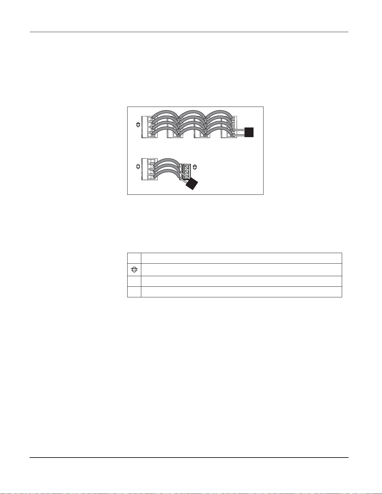
RS-485 wiring
Connect the devices on the RS-485 bus in a point-to-point configuration, with the (+) and
(-) terminals from one device connected to the corresponding (+) and (-) terminals on the
next device.
RS-485 wiring
RS-485 cable
Use a shielded 1.5 twisted pair or 2 twisted pair RS-485 cable to wire the devices. Use
one twisted pair to connect the (+) and (-) terminals, and use the other insulated wire to
connect the C terminals.
RS-485 terminals
Common. This provides the voltage reference (zero volts) for the data plus and data minus signals.
C
Shield. Connect the bare wire to this terminal to help suppress signal noise that may be present.
Ground the shield wiring at one end only (either at the master or the last slave device, but not both).
Data minus. This transmits/receives the inverting data signals.
-
Data plus. This transmits/receives the non-inverting data signal.
+
RS-485 maximum cable length
The total distance for devices connected on an RS-485 bus should not exceed 1200 m
(4000 ft).
RS-485 network configuration
After you have wired the RS-485 port and powered up the meter, you must configure the
serial communications port in order to communicate with the meter.
Each device on the same RS-485 communications bus must have a unique address and
all connected devices must be set to the same protocol, baud rate, and parity (data
format).
NOTE: To communicate with the meter using ION Setup, you must set the parity to
“None” for all devices in the RS-485 network.
For meters that do not have a display, you must first wire and configure each one
separately before connecting these meters to the same RS-485 bus.
© 2014 Schneider Electric All Rights Reserved26

PowerLogic™ PM5100 series user guide Chapter 3—Hardware Reference
D1 -/C
(60)
(57)
LOAD
< 20mA
< 40Vdc
Related topics
• To configure RS-485 communications, see “Setting up serial communications” on
page 34.
Digital outputs
The meter is equipped with a digital output port (D1). You can configure the digital output
for use in the following application:
• energy pulsing applications, where a receiving device determines energy usage by
counting the k_h pulses (k_h = kWh, kVARh or kVAh depending on the energy
parameter selected) coming from the meter’s digital output port.
The digital output can handle voltages less than 40 V DC. For higher voltage applications,
use an external relay in the switching circuit.
Digital output connections
Related topics
• See “Digital output applications” on page 47 for digital output use and configuration
details.
© 2014 Schneider Electric All Rights Reserved 27

PowerLogic™ PM5100 series user guide Chapter 3—Hardware Reference
© 2014 Schneider Electric All Rights Reserved28
PowerLogic™ PM5100 series user guide Chapter 4—Front panel display and meter setup
B
A
C
G
E
F
D
C
B
Chapter 4—Front panel display and meter setup
The front panel display lets you use the meter to perform various tasks such as setting
up the meter, displaying data screens, acknowledging alarms, or performing resets.
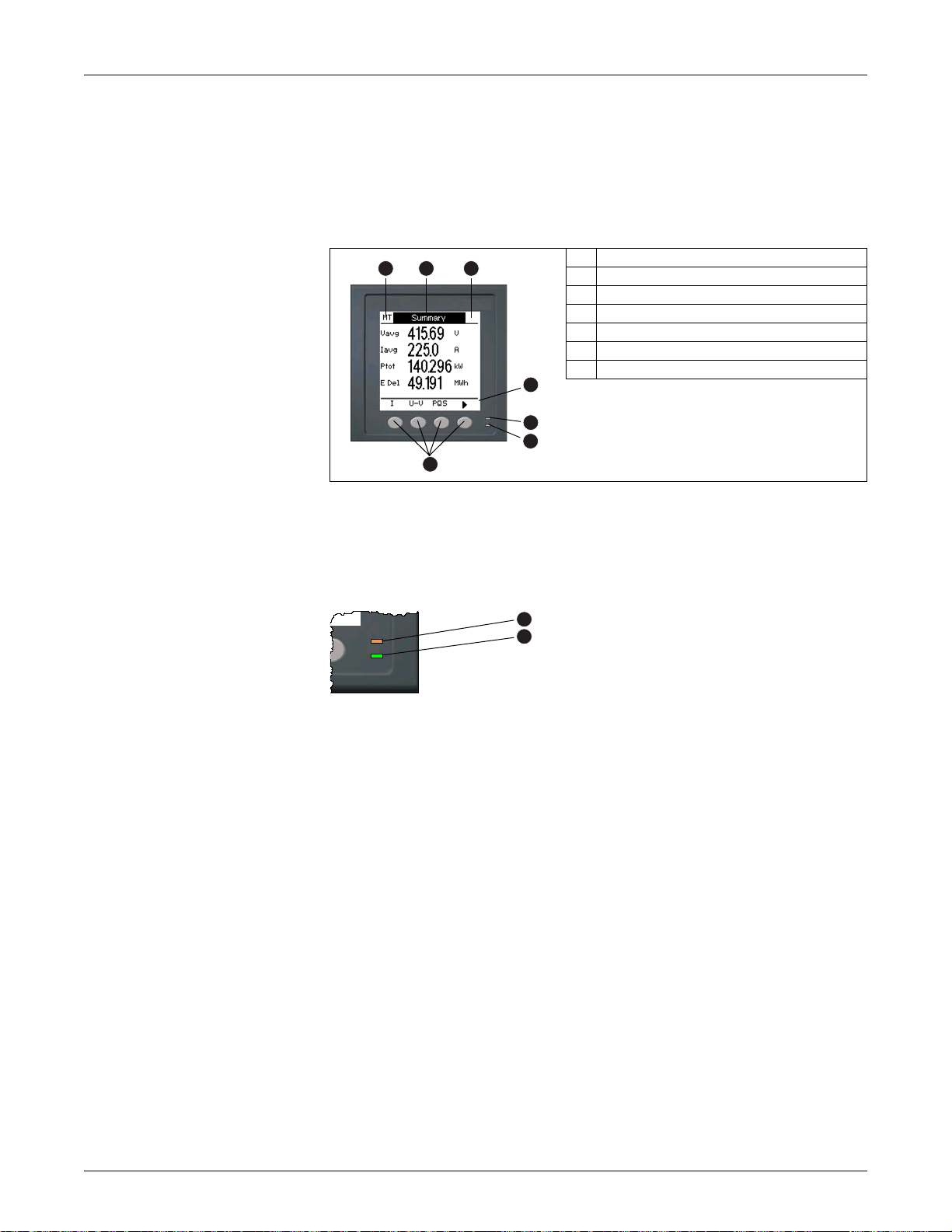
Parts of the display
A Navigation / menu selection buttons
B Heartbeat / communications LED (green)
C Alarm / energy pulsing LED (orange)
D Navigation symbols or menu options
E Right notification area
F Screen title
G Left notification area
LED indicators
The meter has two LED indicators on the front panel.
Front panel LEDs
Heartbeat / communications LED
The (green) heartbeat / communications LED blinks at a slow, steady rate to indicate
the meter is operational. The LED flashes at a variable, faster rate when the meter is
communicating over a Modbus serial communications port.
You cannot configure this LED for other purposes.
NOTE: A heartbeat LED that remains lit and does not blink (or flash) indicates a
possible hardware problem. In this case, power down the meter and reapply power. If
the LED still does not blink or flash, contact Technical Support.
Alarm / energy pulsing LED modes
The (orange) alarm / energy pulsing LED can be configured for alarm notification or
energy pulsing.
Alarm / energy pulsing LED (orange)
Heartbeat / communications LED (green)
• When configured for alarm notification, this LED flashes when a high, medium or
low priority alarm is active. This provides a visual indication of an active alarm
condition, or an inactive but unacknowledged high priority alarm.
• When configured for energy pulsing, this LED flashes at a rate proportional to the
amount of energy consumed. This is typically used to verify the meter’s accuracy.
© 2014 Schneider Electric All Rights Reserved 29
 Loading...