


Schneider Electric AM-731, AM-732, AM-733, AM-734 Installation Instructions

Printed in U.S.A. 6-10 Copyright 2010 Schneider Electric All Rights Reserved. F-27203-3
Application
The AM-731, AM-732, AM-733 and AM-734 linkage
kits are designed to provide mounting of Schneider
Electric DuraDrive™ linear actuators directly to two-
way and three-way valves. This combination will
provide linear travel to valves from 1-1/4" to 2" VB-
7XXX and 2-1/2" to 4" VB-9XXX.
Features
• Direct mounting of linear actuators to valves
AM-731, AM-732,
AM-733, AM-734
Linkage Kits
Schneider Electric DuraDrive
Linear Series Actuators
General Instructions
AM-734
AM-731
AM-732
AM-733

2 Copyright 2010 Schneider Electric All Rights Reserved. F-27203-3
Table-1 Specifications.
INSTALLATION
Inspection Inspect the package for damage. If damaged, notify the appropriate carrier immediately. If
undamaged, open the package and inspect the device for obvious damage. Return
damaged products.
Requirements • Pliers for removing and inserting connecting pin
• Installer must be a qualified, experienced technician
• TOOL-37, 1-1/2" - 3" adjustable spanner wrench for valve mounting nut
• 5/16" and 3/4" open-end wrench for stem jam nuts
• 1/8" Allen wrench
• Size 10 IP Torx Plus bit
• 5/8", 1-1/2", and 1-3/8" open end wrenches
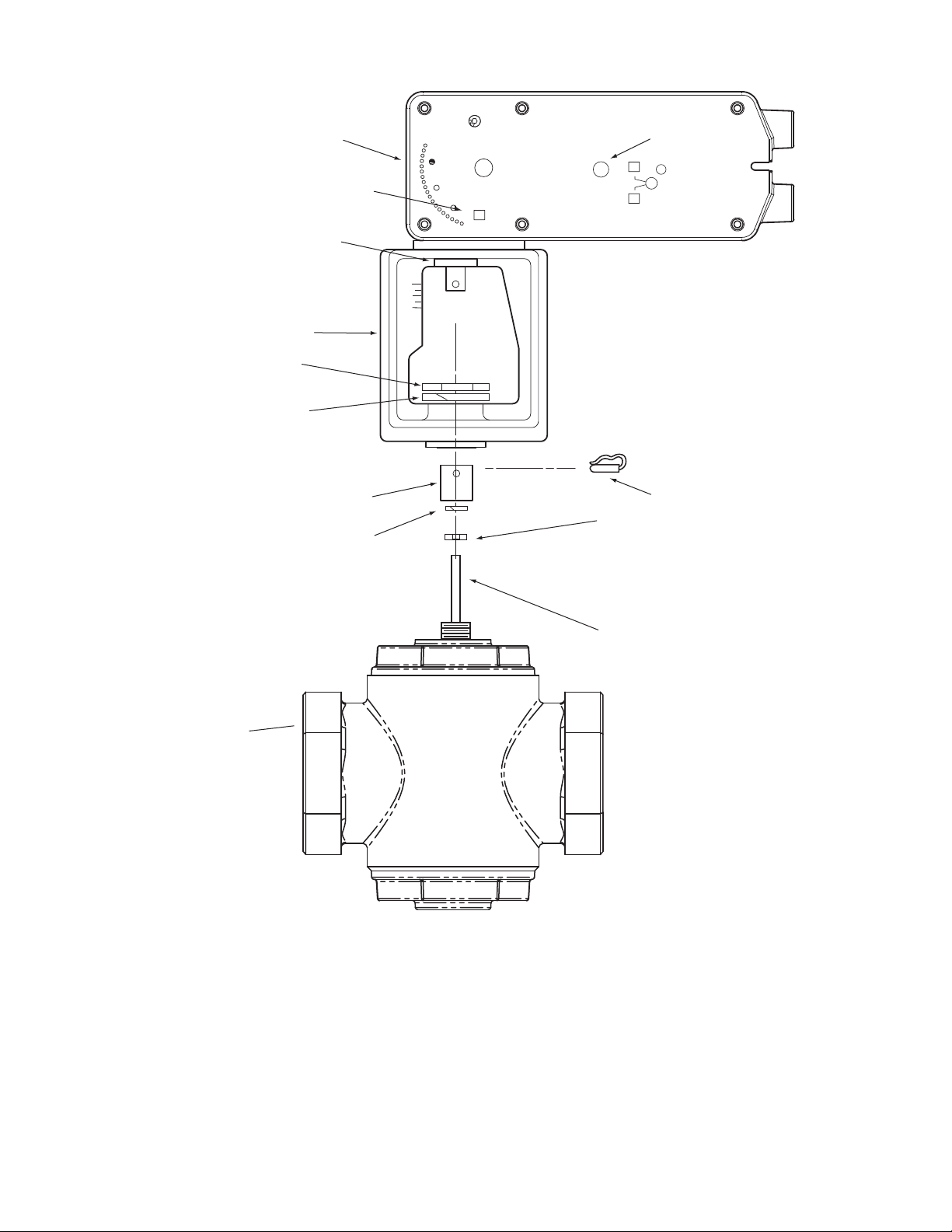
Figure-1 AM-731 Kit with MX51-720X Actuator, Exploded View.
Part Number
Used With
Actuator
Used With Valves Included With Actuator
AM-731 MX51-720x Current 1-1/4" to 2" VB-7XXX Yes
AM-732 MX61-720x Current 2-1/4" to 4" VB-9XXX Yes
AM-733 MX61-720x
Obsolete 1-1/2" and 2" VB-9XXX after date code
9404
No
AM-734 MX61-720x
Obsolete 1-1/2" and 2" VB-9XXX before date code
9404
No
a Not included with linear actuator.
b AM-731 parts
Valve Body
Hex Mounting Nut
Stem Extension
(small)
Mounting Bracket
Rack
Linear Actuator
Manual Override
Connecting Pin
Jam Nut
Valve Stem
R
L
L
Set Screw
Lock Washer
b
b
b
b
a
a
a
b

F-27203-3 Copyright 2010 Schneider Electric All Rights Reserved. 3
.
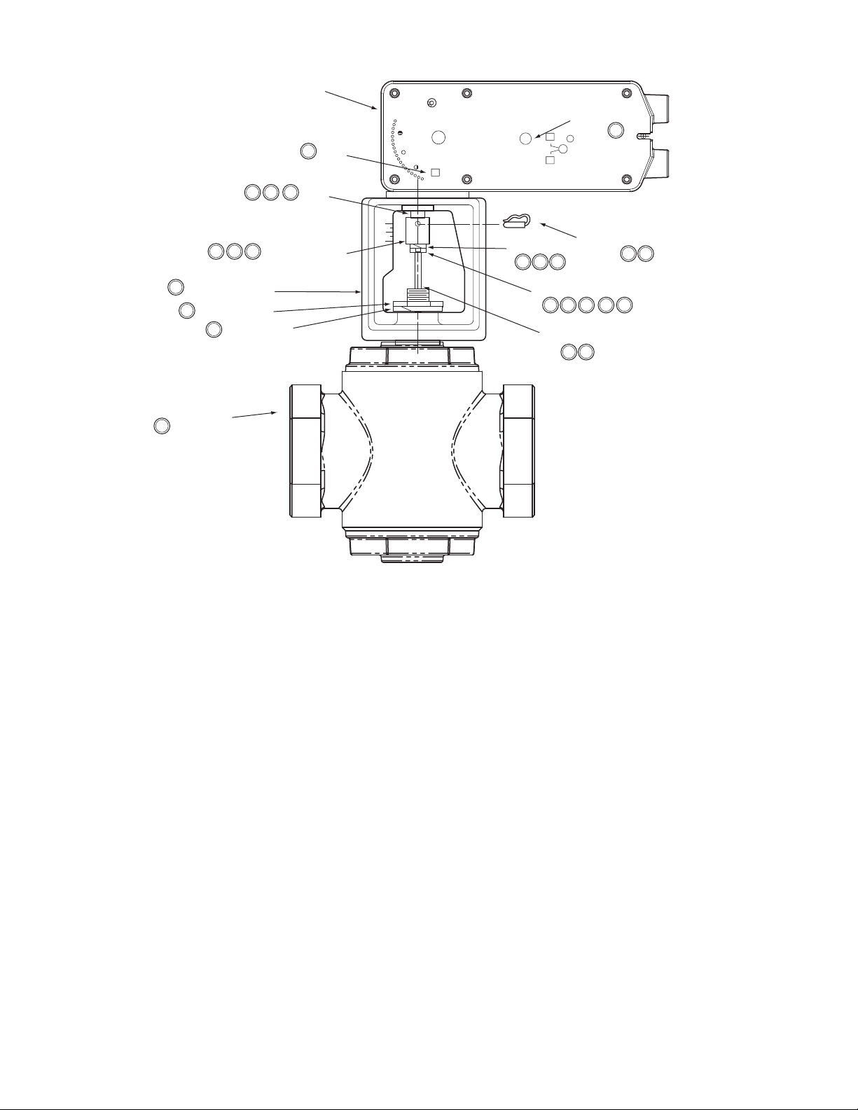
Figure-2 Typical Assembly and Installation of AM-731 Linkage Kit with MX51 Series Actuator to 1-1/4" to 2"
VB-7XXX Series Valve Bodies, Stem-Up Closed or Open, 2-Way and 3-Way Valves.
Installation: AM-731 linkage kit with MX51-720X Series Actuator to 1-1/4" to
2
" VB-7XXX Series Valve Bodies, Stem-Up Closed or Open, 2-Way and 3-Way
A. Install the actuator onto the valve. Set up the assembly according to the numbered steps
in Figure-2.
1. Locate the jam nut that came packaged with the kit.
2. Screw the jam nut onto the valve stem all the way as far as it will go. You may need to
use a 5/16" (TOOL-20-1) open-end wrench. At least 1/2" of the valve stem should
extend above the nut.
3. Place lock washer over valve stem.
4. Thread the stem extension onto the valve stem, making contact with the lock washer
and jam nut.
5. Ensure 15
o
or 1-1/2 turns of manual override for actuator preload (Figure-12).
6. Orient the actuator mounting bracket on the valve and tighten the hex mounting nut
securely against the bracket using TOOL-37. Raise the valve stem to the full up
position.
7. Rotate stem extension until the through hole lines up with the through hole of actuator
rack. Insert connecting pin to secure stem extension and tighten jam nut against stem
extension using 5/16" (TOOL-20-1) open end wrench.
8. Affix open/closed label to the indicator in the appropriate position.
9. Insert set screw packaged with actuator into the most accessible side. Tighten with a
size 10 IP Torx Plus bit to 20-25 lb-in (2.3-2.8 N-m).
B. Apply power to the actuator and check the system operation for heating or cooling output
in response to the control signal.
*Not included with linear actuator.
Valve Body*
Hex Mounting Nut*
Stem Extension
Mounting Bracket
Rack
Linear Actuator
Manual Override
Connecting Pin
Jam Nut
Valve Stem*
1
7
74
2
7
6
74
6
6
6
R
L
L
Lock Washer
4
9
Set Screw
8
4
4
5
Label
3
4
4 Copyright 2010 Schneider Electric All Rights Reserved. F-27203-3
Figure-3 AM-732 with MX61-720X Actuator, Exploded View.
Valve Body
Lock Washer
Stem Extension
(large)
Mounting Bracket
Rack
Linear Actuator
a Not included with linear actuator.
b AM-732 parts - included with actuator.
Manual Override
Connecting Pin
Jam Nut
Valve Stem
R
L
L
a
a
b
b
b
b
Lock Washer
b
Spanner Nut
a
Label
F-27203-3 Copyright 2010 Schneider Electric All Rights Reserved. 5
Figure-4 Typical Assembly and Installation of AM-732 Linkage Kit with MX61 Series Actuator to 2-1/2" to 4"
VB-9XXX Series Valve Bodies, Stem-Up Closed, 2-Way and 3-Way.
Installation: AM-732 linkage kit to MX61-720X Series Actuator to 2-1/2" to 4"
VB-9XXX Series Valve Bodies, Stem-Up Closed, 2-Way and 3-Way
A. Install the actuator onto the valve. Set up the assembly according to the numbered steps
in Figure-4.
1. Locate the jam nut that came packaged with the kit.
2. Screw the jam nut onto the valve stem all the way as far as it will go (you may need to
use a 3/4" open-end wrench). At least 1/2" of the valve stem should extend above the
nut. Place the lock washer over the valve stem.
3. Thread the stem extension onto the valve stem, making contact with the lock washer
and jam nut.
4. Ensure 15
o
or 1-1/2 turns of manual override for actuator preload (Figure-12).
5. Orient the actuator mounting bracket on the valve, place lock washer over valve stem
and tighten the mounting nut securely against the bracket using 1-1/2" - 3" adjustable
spanner wrench. Raise the valve stem to the full up position.
6. Rotate stem extension until the through hole lines up with the through hole of actuator
rack. Insert connecting pin to secure stem extension and tighten jam nut against stem
extension using 3/4” open end wrench.
7. Affix open/close label to the indicator in the appropriate position.
B. Apply power to the actuator and check the system operation for heating or cooling output
in response to the control signal.
Valve Body*
Spanner Nut*
Stem Extension
Mounting Bracket
Rack
Linear Actuator
6
5
64
5
*Not included with linear actuator.
Manual Override
Connecting Pin
Jam Nut
Valve Stem*
1
6
63
R
L
L
43
Lock Washer
5
5
Lock Washer
4
4
4
4
32
32
Label
7
3
3
 Loading...