


Schneider Electric Altivar312 User Manual
2354235 11/2008
Altivar 312
Variable speed drives
for asynchronous motors
CANopen® communication manual
09/2009
BBV52819
www.schneider-electric.com


Contents
Important Information __________________________________________________________________________________________ 4
Before you begin______________________________________________________________________________________________ 5
Documentation structure________________________________________________________________________________________ 6
Presentation _________________________________________________________________________________________________ 7
Hardware setup CANopen
Hardware setup CANopen
Configuration _______________________________________________________________________________________________ 17
Signalling __________________________________________________________________________________________________ 18
Software setup ______________________________________________________________________________________________ 19
Software setup with PL7 and SyCon _____________________________________________________________________________ 22
Description of the services _____________________________________________________________________________________ 31
Object dictionary_____________________________________________________________________________________________ 45
®
daisy chain - option VW3A31208 __________________________________________________________ 8
®
tap - option VW3CANTAP2 ______________________________________________________________ 12
BBV52819 09/2009 3
Important Information
The addition of this symbol to a Danger or Warning safety label indicates that an electrical hazard exists, which will result in
personal injury if the instructions are not followed.
This is the safety alert symbol. It is used to alert you to potential personal injury hazards. Obey all safety messages that follow
this symbol to avoid possible injury or death.
NOTICE
Read these instructions carefully, and look at the equipment to become familiar with the device before trying to install, operate, or maintain
it. The following special messages may appear throughout this documentation or on the equipment to warn of potential hazards or to call
attention to information that clarifies or simplifies a procedure.
DANGER
DANGER indicates an imminently hazardous situation, which, if not avoided, will result in death or serious injury.
WARNING
WARNING indicates a potentially hazardous situation, which, if not avoided, can result in death, serious injury or
equipment damage.
CAUTION
CAUTION indicates a potentially hazardous situation, which, if not avoided, can result in injury or equipment
damage.
CAUTION
CAUTION, used without the safety alert symbol, indicates a potentially hazardous situation which, if not avoided,
can result in equipment damage.
PLEASE NOTE
The word "drive" as used in this manual refers to the controller portion of the adjustable speed drive as defined by NEC.
Electrical equipment should be installed, operated, serviced, and maintained only by qualified personnel. No responsibility is assumed by
Schneider Electric for any consequences arising out of the use of this product.
© 2009 Schneider Electric. All Rights Reserved.
4 BBV52819 09/2009
Before you begin
Read and understand these instructions before performing any procedure with this drive.
DANGER
HAZARD OF ELECTRIC SHOCK, EXPLOSION, OR ARC FLASH
• Read and understand this manual before installing or operating the Altivar 312 drive. Installation, adjustment, repair, and
maintenance must be performed by qualified personnel.
• The user is responsible for compliance with all international and national electrical code requirements with respect to grounding of
all equipment.
• Many parts of this drive, including the printed circuit boards, operate at the line voltage. DO NOT TOUCH. Use only electrically
insulated tools.
• DO NOT touch unshielded components or terminal strip screw connections with voltage present.
• DO NOT short across terminals PA/+ and PC/– or across the DC bus capacitors.
• Before servicing the drive:
- Disconnect all power, including external control power that may be present.
- Place a “DO NOT TURN ON” label on all power disconnects.
- Lock all power disconnects in the open position.
- WAIT 15 MINUTES to allow the DC bus capacitors to discharge.
- Measure the voltage of the DC bus between the PA/+ and PC/– terminals to ensure that the voltage is less than 42 Vdc.
- If the DC bus capacitors do not discharge completely, contact your local Schneider Electric representative. Do not repair or
operate the drive
• Install and close all covers before applying power or starting and stopping the drive.
Failure to follow these instructions will result in death or serious injury.
DANGER
UNINTENDED EQUIPMENT OPERATION
• Read and understand this manual before installing or operating the Altivar 312 drive.
• Any changes made to the parameter settings must be performed by qualified personnel.
Failure to follow these instructions will result in death or serious injury.
WARNING
DAMAGED DRIVE EQUIPMENT
Do not operate or install any drive or drive accessory that appears damaged.
Failure to follow these instructions can result in death, serious injury, or equipment damage.
WARNING
LOSS OF CONTROL
• The designer of any control scheme must
- consider the potential failure modes of control paths and, for certain critical control functions,
- provide a means to achieve a safe state during and after a path failure.
Examples of critical control functions are emergency stop and overtravel stop.
• Separate or redundant control paths must be provided for critical control functions.
• System control paths may include communication links. Consideration must be given to the implications of unanticipated
transmission delays or failures of the link.
a
Failure to follow these instructions can result in death, serious injury, or equipment damage.
a. For additional information, refer to NEMA ICS 1.1 (latest edition), “Safety Guidelines for the Application, Installation, and Maintenance of Solid State Control” and to
NEMA ICS 7.1 (latest edition), “Safety Standards for Construction and Guide for Selection, Installation and Operation of Adjustable-Speed Drive Systems.”
BBV52819 09/2009 5

Documentation structure
The following Altivar 312 technical documents are available on the Schneider Electric website (www.schneider-electric.com) as well as on
DVD-ROM (reference VW3A8200).
Installation manual
This manual describes how to install and wire the drive.
Programming manual
This manual describes the functions, parameters and use of the drive terminal (integrated display terminal, optional graphic display terminal
and optional remote terminal).
The communication functions are not described in this manual, but in the manual for the bus or network used.
Simplified manual
This manual is a simplified version of the User manual. This manual is delivered with the drive.
Quick Start sheet
The Quick Start describes how to wire and configure the drive to start motor quickly and simply for simple applications. This document is
delivered with the drive.
Communication manuals: Modbus and CANopen
These manuals describe the assembly, connection to the bus or network, signaling, diagnostics, and configuration of the communicationspecific parameters.
They also describe the protocol communication services.
®
Communication variables guide
This manual defines the drive control processes and the drive variables which can be accessed by the communication buses: Modbus,
CANopen
®
, ...
6 BBV52819 09/2009

Presentation
The CANopen® socket on the Altivar 312 can be used for the following functions:
• Configuration
• Settings
• Control
• Monitoring
This guide contains information on installation and describes the CANopen
describes the operating modes, as well as the Altivar 312 variables and parameters which can be accessed via the communication bus.
®
services available. The "communication variables" guide
BBV52819 09/2009 7
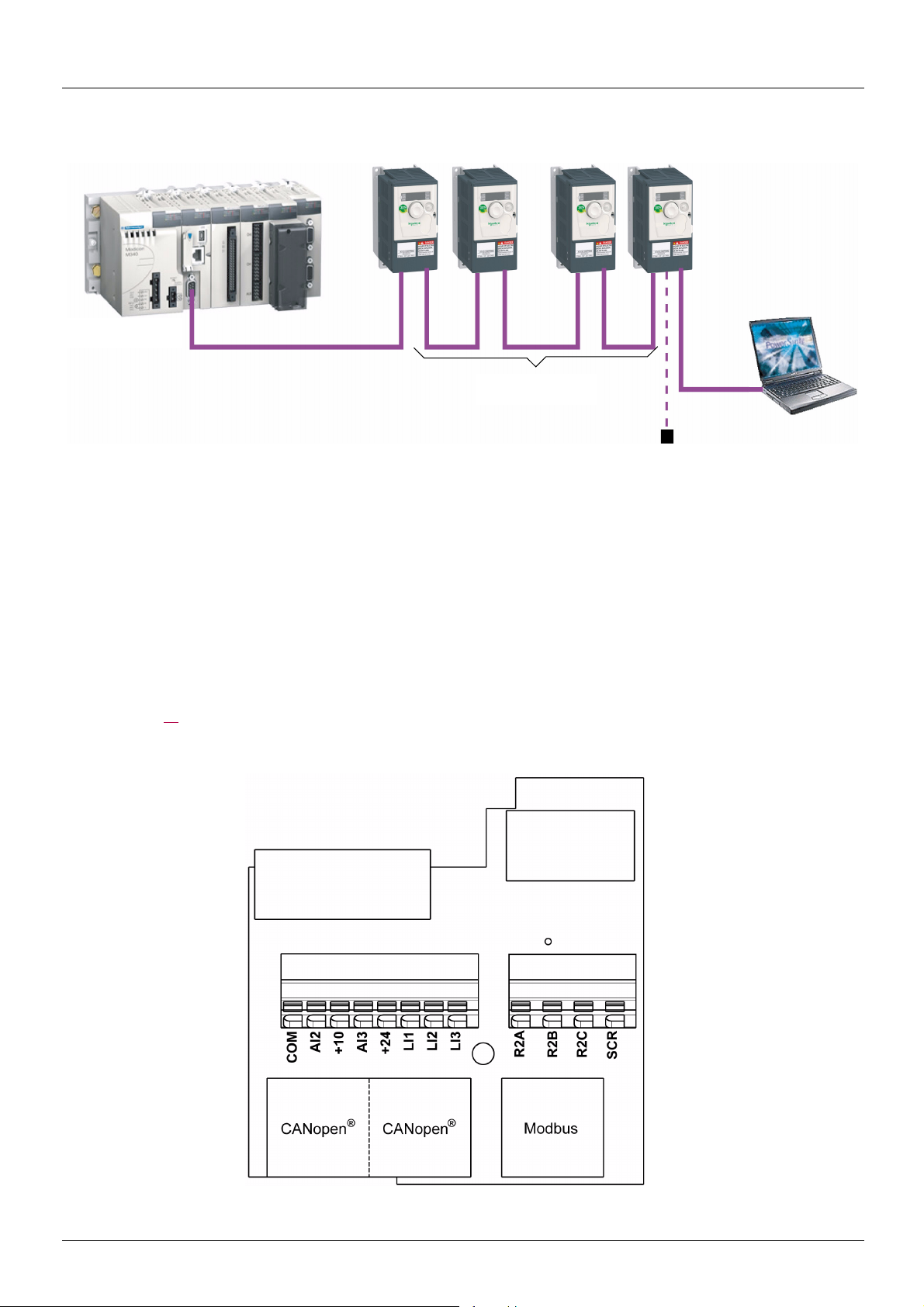
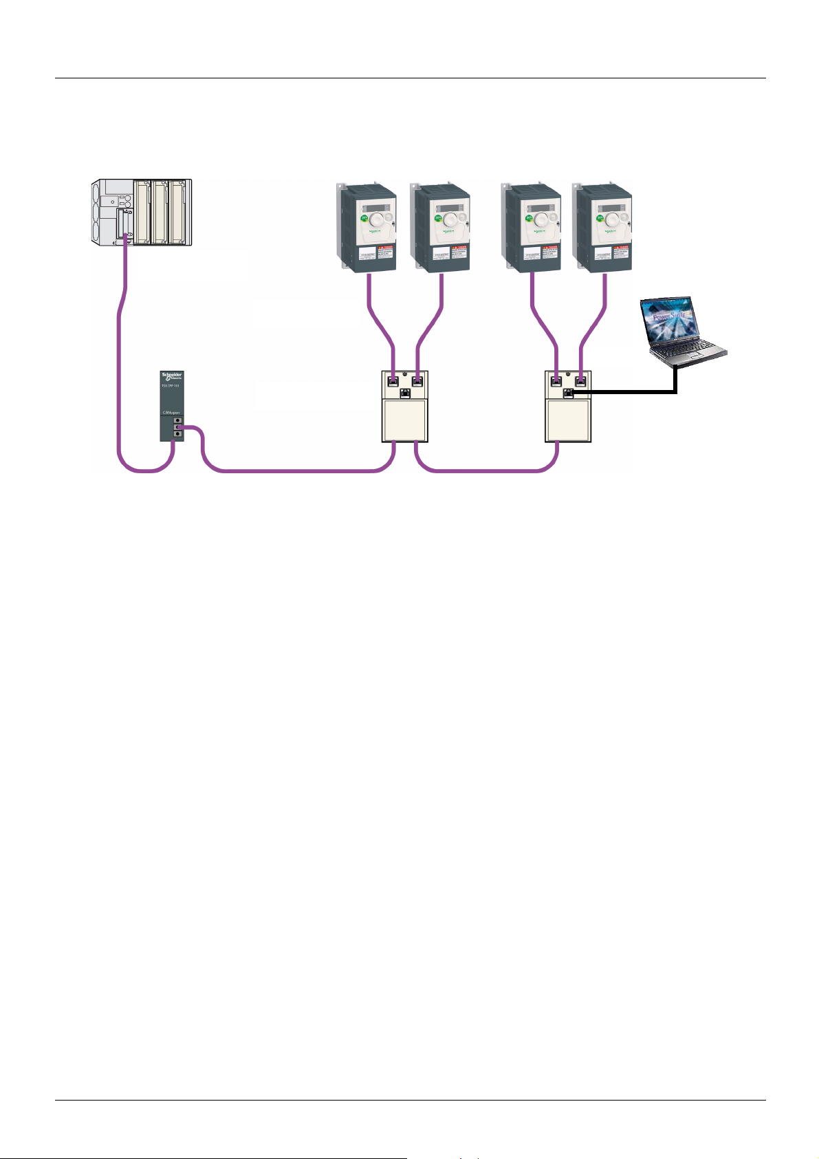
Hardware setup CANopen® daisy chain - option VW3A31208
PowerSuite
or SoMove
Line Termination
TCS CAR013M120
Modbus
Master PLC
M340 CANopen
®
ATV 312 drop cord
VW3 CAN CA RR
p
The following diagram shows an example of four ATV 312, with each one a CANopen® daisy chain module inside, and connected to M340.
®
ATV312 CANopen
• Two RJ45 connectors allow the creation of a CANopen
cord is a cable equipped with 2 RJ45 connectors. Two lengths are available: 0.3 m (0.98 ft), reference: VW3 CAN CA RR 03 and
1 m (3.28 ft), reference: VW3 CAN CA RR1.
• A third RJ45 connector to connect the ATV312 with the commissioning tools like : PowerSuite, SoMove, Bluetooth™ adaptor, Simpleloader and Multi-loader, or to connect Modbus devices (PLC, HMI, etc…).
daisychain option card (reference: VW3 A31208, supplied separately) provides:
®
network by using cables equipped with RJ45: ATV 312 CANopen® drop
The network termination is done by inserting on the last available RJ45 port of the last device on the network a line termination (reference
TCS CAR013M120). This line termination is fitted with a RJ45 to be directly inserted on the module.
As the VW3 A31208 replaces the base terminal card of the ATV312, it is also equipped with digital and analog IOs.
Note: maximum bus length are divided by 2 when an Altivar 312 is placed on a CANopen
See values page 17
.
®
bus with CANopen® daisychain VW3A31208.
Presentation
8 BBV52819 09/2009
Hardware setup CANopen® daisy chain - option VW3A31208
Receipt
• Check that the card catalog number marked on the label is the same as that on the delivery note corresponding to the purchase order.
• Remove the option card from its packaging and check that it has not been damaged in transit.
Installing the card in the drive
DANGER
UNINTENDED EQUIPMENT OPERATION
• Do not plug or unplug the terminal board while drive is powered.
• Check the tightening of the fixing screw after any manipulation on the terminal board.
Failure to follow these instructions will result in death or serious injury.
DANGER
HAZARD OF ELECTRIC SHOCK, EXPLOSION, OR ARC FLASH
Do not touch the terminal board before :
• removing power on the drive,
• removing any voltage on input and output terminals.
Failure to follow these instructions will result in death or serious injury.
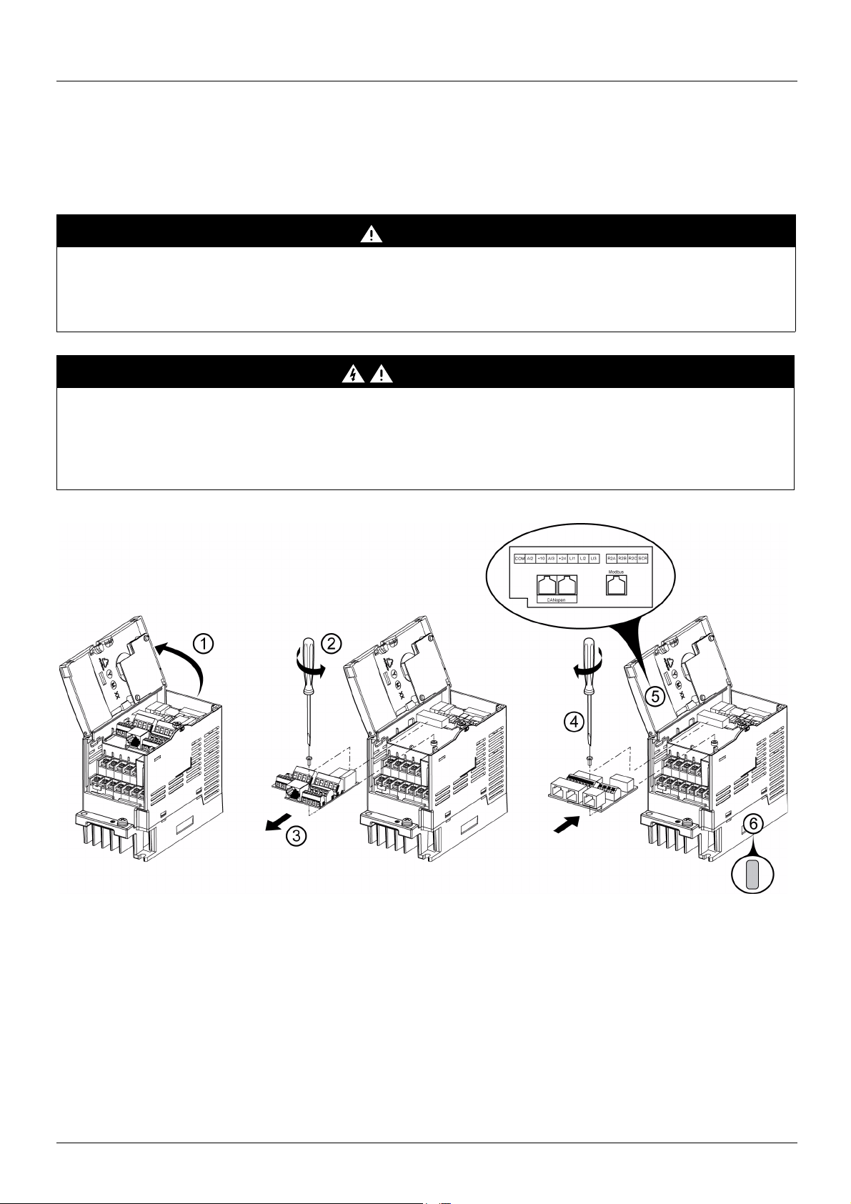
Install the CANopen® daisy chain card in ATV312 as follows:.
1. Open the ATV312 front cover.
2. Remove the terminal board fixing screw and take off the ATV312 standard terminal board.
(Be careful not to lose the terminal board fixing screw when removed since it may be used again.)
This step does not apply if you are using an ATV312.... B (product without standard IO terminal).
3. Perform wiring before installing CANopen
4. Install the CANopen
(M3 tapping screw tightening torque: 0.7 to 0.8Nm).
5. Stick the new cabling label on the reverse side of the ATV312 front cover.
6. Stick the CANopen® daisy chain card nameplate near the ATV312 nameplate. (Be careful not to cover slits on the ATV312 enclosure)
Note: To install or remove the terminal board, make it slide in or out in parallel with board to avoid mechanical stress on the board.
BBV52819 09/2009 9
®
daisy chain card and secure it with the board fixing screw
®
daisy chain card.
Hardware setup CANopen® daisy chain - option VW3A31208
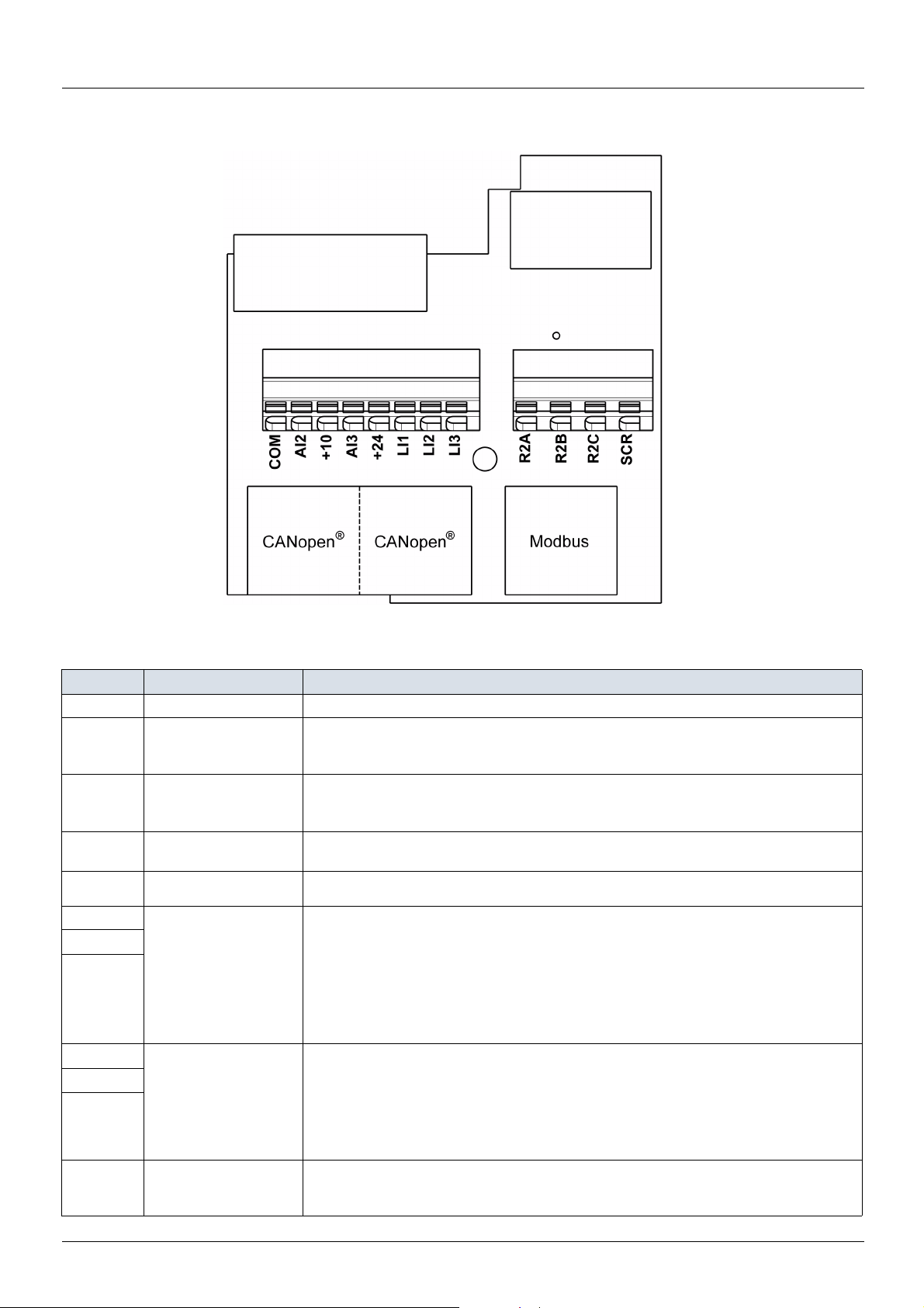
Description of the terminals
Control terminals characteristics
Terminal Function Electrical characteristics
COM Analog I/O common 0 V
Analog bipolar voltage input ±10 V:
AI2 Analog voltage input
Power supply for the
10 V
AI3 Analog current input
24 V Logic input power supply
LI1
LI2
LI3
R2A
R2B
R2C
SCR (Screen)
reference potentiometer
(2.2 to 10 k
Logic inputs
Configurable relay
outputs 1 relay logic
output, one “N/C” contact
and one “N/O” contact
with common point.
Ω)
• impedance 30 k
• maximum safe voltage 30 V
+10 V (+ 8% - 0):
• 10 mA max
• protected against short-circuits and overloads
Analog current input X-Y mA by programming X and Y from 0 to 20 mA:
impedance 250
• + 24 V protected against short-circuits and overloads, min 19 V, max 30 V
• Maximum customer current available 100 mA
Programmable logic inputs:
• Impedance 3.5 k
• + 24 V internal or 24 V external power supply (min. 19 V, max. 30 V)
• Max. current: 100 mA
• Max. sampling time: 4 ms
Source position: Positive logic State 0 if < 5 V or logic input not wired, state 1 if > 11 V
Sink position: Negative logic State 0 if > 19 V or logic input not wired, state 1 if < 13 V
CLI position: Connection to PLC output
• Minimum switching capacity: 10 mA for 5 Vdc
• Maximum switching capacity on resistive load (cos ϕ = 1 and L/R= 0 ms).
5 A for 250 Vac and 30 Vdc
• Maximum switching capacity on inductive load (cos ϕ = 0.4 and L/R = 7 ms):
2 A for 250 Vac and 30 Vdc
• Sampling time 8 ms
• Service life: 100,000 operations at maximum switching power
CANopen
This terminal is not connected to other circuits in this board.
Ground this terminal in a location separated from the ground of power line.
®
Ω
Ω
Ω
communication shield terminal.
10 BBV52819 09/2009
Hardware setup CANopen® daisy chain - option VW3A31208
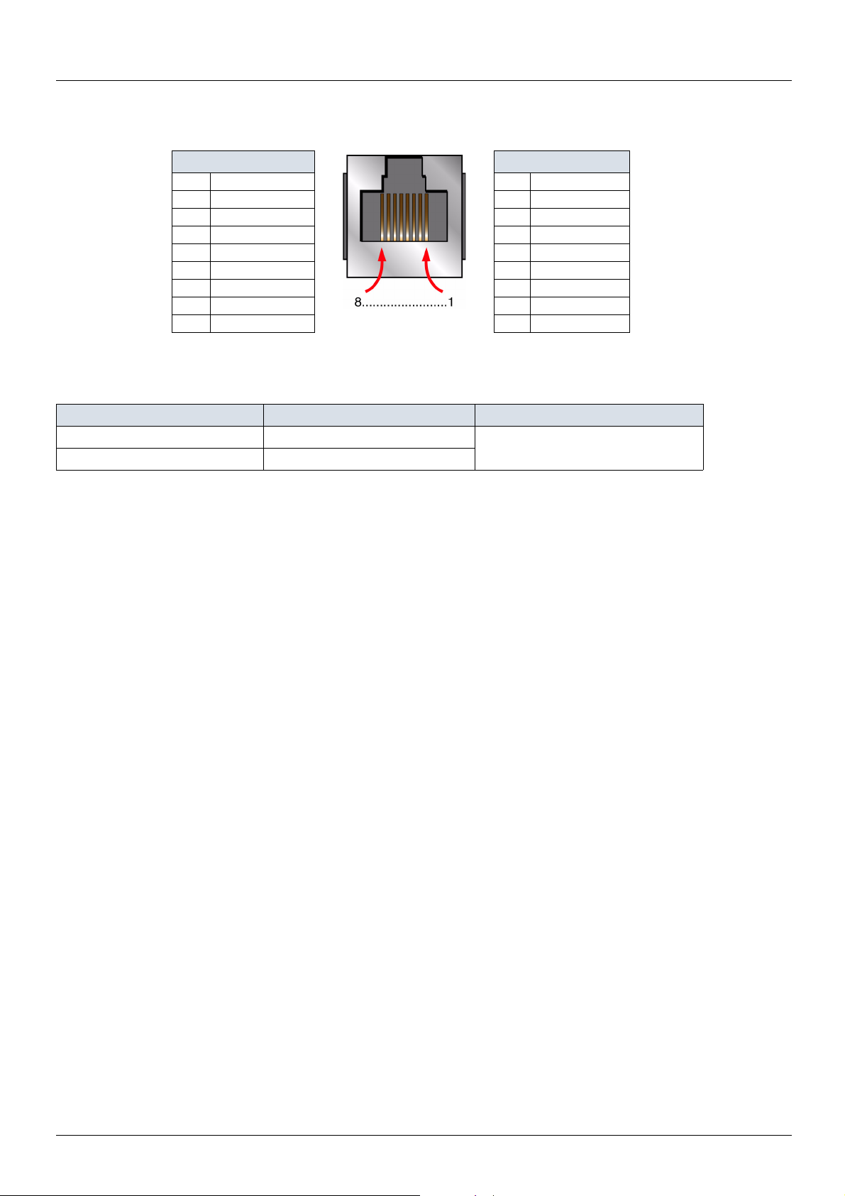
CANopen® and Modbus connectors
CANopen
Pin RJ 45 Signal Pin RJ 45 Signal
1 CAN_H 1 Not connected
2 CAN_L 2 Not connected
3 CAN_GND 3 Not connected
4 Not connected 4 D1
5 Not connected 5 D0
6 Not connected 6 Not connected
7 Not connected 7 VP (1)
8 Not connected 8 Common
®
Modbus
(1) Reserved for RS232/RS485 converter
Wire sizes
ATV312 Control terminals Applicable wire size mm² (AWG) (2) Tightening torque N·m (lb.in) (3)
R2A, R2B, R2C 0.75 to 1 (18 to 16) 0.5 to 0.6 (4.4 to 5.3)
Other terminals 0.14 to 0.5 (26 to 20)
(2)The value in bold corresponds to the minimum wire gauge to permit secureness.
(3)Recommended to maximum value.
BBV52819 09/2009 11
Hardware setup CANopen® tap - option VW3CANTAP2
PowerSuite
CANopen®
trunk cable
CANopen
®
trunk cable
ATV 312 CANopen®
tap VW3 CAN TAP 2
ATV 312 drop cord
VW3 CAN CA RR
p
Master PLC
+ TSX CPP 110
Modbus
Legacy CANopen® wiring solution for ATV 312
The following diagram shows an example of four ATV 312, connected to a master PLC Premium with a CANopen® master PCMCIA card
(TSX CPP 110).
Various accessories are available from the catalog to facilitate the connection of these devices.
ATV 312 CANopen
screw terminals embedded connectors. Two RJ45 connectors allow the connection of two Altivar 312 by ATV 312 CANopen
®
tap is a passive tap (reference: VW3CANTAP2) It can be connected on a CANopen® trunk cable, using the two 5-
®
drop cords.
One RJ45 connector is designed to interface these two Altivar 312 with PowerSuite (Commissioning software tool for PC or Pocket PC).
If only one ATV 312 is connected on the tap it should be on the connector labelled "ATV1". If two ATV 312 are connected, PowerSuite can
access the two drives in multidrop mode. The Modbus address of each drive must be different.
A remote terminal (VW3A31101) can also be connected to the "PowerSuite" connector, but in this case, only one ATV 312 drive can be
connected to the CANopen
ATV 312 CANopen
®
tap (on the plug labelled "ATV1").
®
drop cord is a cable equipped with 2 RJ45 connectors. Two lengths are available: 0.3 m (0.98 ft), reference:
VW3CANCARR03) and 1 m (3.28 ft), reference: VW3CANCARR1.
Note: Only a 0.3 m (11.8 in.) drop cord can be used in a CANopen
®
network at a speed of 1 Mbits/s.
12 BBV52819 09/2009
Hardware setup CANopen® tap - option VW3CANTAP2
1
ATV1 ATV2
PowerSuite
S1 S2
S3
ON
S4 S5
OFF
23
4
2
4
7
9
8
10
3
5
7
6
9
8
11
10
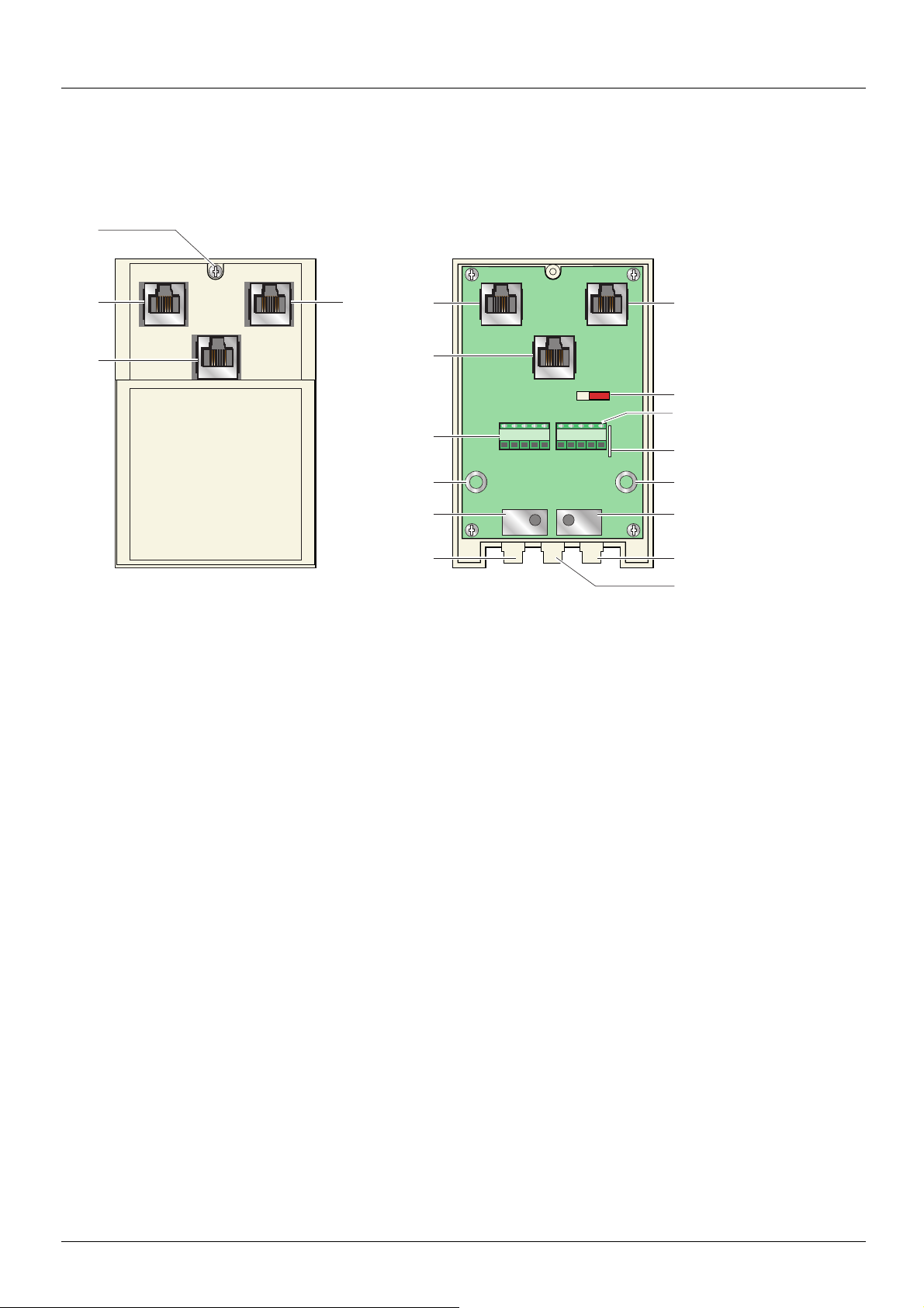
Description of the ATV 312 CANopen® tap
External view Internal view
1. Cover screw.
2. "ATV1" female RJ45 connector where the first Altivar 312 drive must be connected.
3. "ATV2" female RJ45 connector where the second, (if any), Altivar 312 drive must be connected. Do not use if a remote terminal is
connected to the "PowerSuite" connector.
4. "PowerSuite" female RJ45 connector, where PowerSuite (PC or Pocket PC) or a remote terminal can be connected.
5. Switch used to connect (ON) or disconnect (OFF) the internal line termination (120 Ω).
6. Lug for connecting the green/yellow grounding wire.
7. CANopen
8. Holes for Ø 4 screws used to mount the tap on a plate or panel, 60 mm (2.36 in.) mounting distance.
9. Ground plate for the trunk cable shield.
10. Openings for the CANopen
11. Opening for the green/yellow grounding wire.
®
terminal blocks, labelled S4 and S5 on the circuit board for wiring of the trunk cable.
®
trunk cable.
BBV52819 09/2009 13
Hardware setup CANopen® tap - option VW3CANTAP2
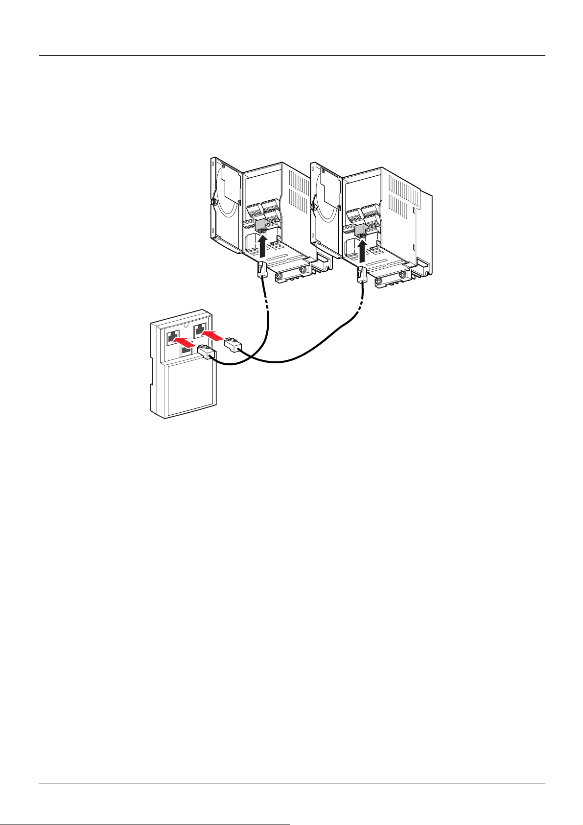
ATV1
ATV2
Power
Suite
Connecting the drive to the ATV 312 CANopen® tap
Connect the cord with 2 RJ45 connectors (VW3 CAN CA RR 03 or VW3 CAN CA RR 1) to the RJ45 connector of the drive and to the "ATV1"
or "ATV2" female RJ45 connector located on the ATV 312 CANopen
If only one Altivar 312 is connected to the ATV 312 CANopen
®
tap (VW3 CAN TAP 2).
®
tap the "ATV1" connector must be used.
14 BBV52819 09/2009
Hardware setup CANopen® tap - option VW3CANTAP2
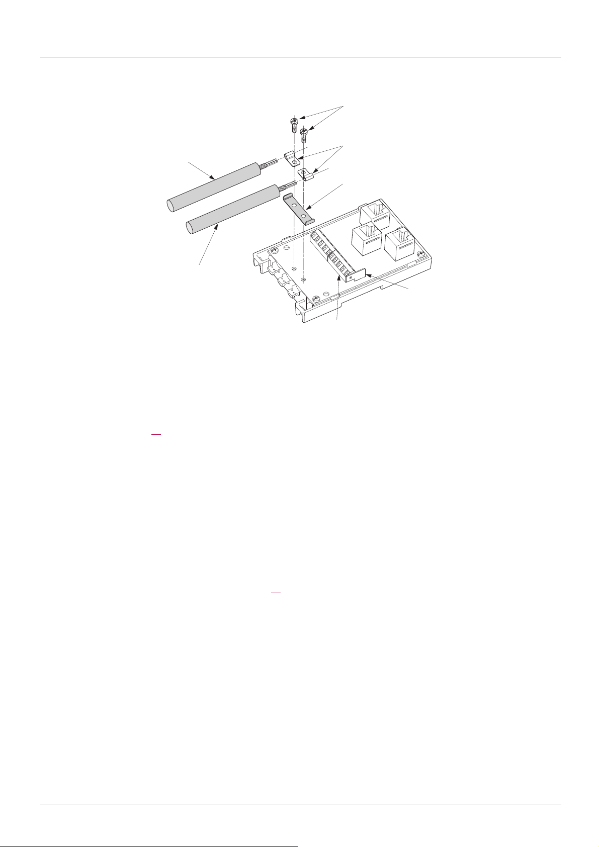
20
19
22
23
21
7
6
Setup of the CANopen® tap
Tools required:
• 2.5 mm flat screwdriver.
Procedure:
Note: the numbers shown below correspond to the numbers in the tap description.
• Unscrew screw 1 page 13
• Attach the tap base to its support:
- either to an AM1-DP200 or AM1-DE 200 DIN rail,
- or to a plate,
- or panel using 2 M4 screws at least 20 mm (0.8 in.) long.
• Prepare trunk cables 20 and 21, as shown on the following pages.
• Position grounding clamps 22 on the cables.
• Position ground connection 23.
• Connect the trunk cables to terminal blocks 7, as shown on the following pages. Use a 2.5 mm flat screwdriver. Thread torque on
terminal block screw
• Screw down the grounding clamps and connections using screws 19.
• Connect the green/yellow grounding wire to the connection lug 6.
• Immobilise the cables using nylon clamps.
• Position micro-switch to ON if line termination is required.
• Break the tabs on the cover so that the cables can pass through.
• Replace cover and fasten it in place with screw 1 page 13
. Open cover.
y 0.25 N·m (2.21 lb.in).
.
BBV52819 09/2009 15
 Loading...