


 Loading...
Quick Start
Micro800 Programmable Controllers: Getting Started with CIP Client Messaging
Catalog Numbers Bulletin 2080-LC30, 2080-LC50

Important User Information
Solid-state equipment has operational characteristics differing from those of electromechanical equipment. Safety Guidelines for the Application, Installation and Maintenance of Solid State Controls (publication SGI-1.1 available from your local Rockwell Automation sales office or online at http://www.rockwellautomation.com/literature/) describes some important differences between solid-state equipment and hard-wired electromechanical devices. Because of this difference, and also because of the wide variety of uses for solid-state equipment, all persons responsible for applying this equipment must satisfy themselves that each intended application of this equipment is acceptable.
In no event will Rockwell Automation, Inc. be responsible or liable for indirect or consequential damages resulting from the use or application of this equipment.
The examples and diagrams in this manual are included solely for illustrative purposes. Because of the many variables and requirements associated with any particular installation, Rockwell Automation, Inc. cannot assume responsibility or liability for actual use based on the examples and diagrams.
No patent liability is assumed by Rockwell Automation, Inc. with respect to use of information, circuits, equipment, or software described in this manual.
Reproduction of the contents of this manual, in whole or in part, without written permission of Rockwell Automation, Inc., is prohibited.
Throughout this manual, when necessary, we use notes to make you aware of safety considerations.
WARNING: Identifies information about practices or circumstances that can cause an explosion in a hazardous environment, which may lead to personal injury or death, property damage, or economic loss.
ATTENTION: Identifies information about practices or circumstances that can lead to personal injury or death, property damage, or economic loss. Attentions help you identify a hazard, avoid a hazard, and recognize the consequence.
SHOCK HAZARD: Labels may be on or inside the equipment, for example, a drive or motor, to alert people that dangerous voltage may be present.
BURN HAZARD: Labels may be on or inside the equipment, for example, a drive or motor, to alert people that surfaces may reach dangerous temperatures.
IMPORTANT Identifies information that is critical for successful application and understanding of the product.
Allen-Bradley, Micro800, Micro830, Micro850, Connected Components Workbench, PanelView, Rockwell Software, Rockwell Automation, and TechConnect are trademarks of Rockwell Automation, Inc.
Trademarks not belonging to Rockwell Automation are property of their respective companies.

Preface
About This Publication
Audience
This publication is designed to provide quickstart instructions for using CIP GENERIC and CIP Symbolic Messaging in Micro830™ and Micro850™ programmable logic controller (PLC). It makes use of sample programs to illustrate the basic steps that a user needs to perform to use the CIP messaging functions in Micro830 and Micro850 controllers.
To assist in the design and installation of your system, refer to the Micro830 and Micro850 Programmable Controllers User Manual publication 2080-UM002.
The beginning of each chapter contains the following information. Read these sections carefully before beginning work in each chapter.
•Before You Begin – This section lists the steps that must be completed and decisions that must be made before starting that chapter. The chapters in this quick start do not have to be completed in the order in which they appear, but this section defines the minimum amount of preparation required before completing the current chapter.
•What You Need – This section lists the tools that are required to complete the steps in the current chapter. This includes, but is not limited to, hardware and software.
•Follow These Steps – This illustrates the steps in the current chapter and identifies which steps are required to complete the examples using specific networks.
To be able to use the CIP messaging feature effectively, you need to be familiar with programming in function block diagram, structured text, and ladder programming.
This quick start works hand-in-hand with Micro830 and Micro850 Programmable Controllers User Manual, publication 2080-UM002.
Required Software
To complete this quick start, the following software is required:
•Connected Components Workbench™ revision 4 and later
Connected Components Workbench is the main programming software for Micro800 systems. It provides a choice of IEC 61131-3 programming languages (ladder diagram, function block diagram, structured text) with user defined function block support that optimizes machine control.
You will need the Connected Components Workbench software to write your function block programs, execute your function blocks, and see results.
Rockwell Automation Publication 2080-QS002A-EN-E - April 2013 |
iii |

Preface
Additional Resources
Resource |
Description |
|
|
Micro830 and Micro850 User Manual, publication |
A detailed description of how to install and use your Micro830 and Micro850 |
2080-UM002 |
programmable controller and expansion I/O system. |
|
|
Micro800 Programmable Controller External AC Power |
Information on wiring and installing the optional AC power supply. |
Supply Installation Instructions, publication 2080-IN001 |
|
|
|
Industrial Automation Wiring and Grounding Guidelines, |
More information on proper wiring and grounding techniques. |
publication 1770-4.1 |
|
|
|
Connected Components Workbench Online Help |
Online Help that provides a description of the different elements of the |
|
Connected Components Workbench software. |
|
|
iv |
Rockwell Automation Publication 2080-QS002A-EN-E - April 2013 |

|
Table of Contents |
|
|
Important User Information . . . . . . . . . . . . . . . . . . . . . . . . . . . . . . . . . . . . . . . |
. ii |
|
Preface |
|
|
About This Publication . . . . . . . . . . . . . . . . . . . . . . . . . . . . . . . . . . . . . . . . . . . |
iii |
|
Audience . . . . . . . . . . . . . . . . . . . . . . . . . . . . . . . . . . . . . . . . . . . . . . . . . . . . . . . . . |
iii |
|
Required Software . . . . . . . . . . . . . . . . . . . . . . . . . . . . . . . . . . . . . . . . . . . . . . . . |
iii |
|
Additional Resources . . . . . . . . . . . . . . . . . . . . . . . . . . . . . . . . . . . . . . . . . . . . . . |
iv |
|
Where to Start |
|
|
Overview . . . . . . . . . . . . . . . . . . . . . . . . . . . . . . . . . . . . . . . . . . . . . . . . . . . . . . . . . |
. 1 |
|
Hardware and Software Compatibility . . . . . . . . . . . . . . . . . . . . . . . . . . . . . . |
. 1 |
|
Follow These Steps . . . . . . . . . . . . . . . . . . . . . . . . . . . . . . . . . . . . . . . . . . . . . . . . |
. 2 |
|
Chapter 1 |
|
Create a Micro800 Project |
Introduction . . . . . . . . . . . . . . . . . . . . . . . . . . . . . . . . . . . . . . . . . . . . . . . . . . . . . |
. 3 |
|
Before You Begin . . . . . . . . . . . . . . . . . . . . . . . . . . . . . . . . . . . . . . . . . . . . . . . . . |
. 3 |
|
What You Need . . . . . . . . . . . . . . . . . . . . . . . . . . . . . . . . . . . . . . . . . . . . . . . . . . |
. 3 |
|
Create a Micro800 Project in Connected Components Workbench . . . |
. 4 |
|
Chapter 2 |
|
Use CIP Symbolic Client |
Introduction . . . . . . . . . . . . . . . . . . . . . . . . . . . . . . . . . . . . . . . . . . . . . . . . . . . . . |
. 7 |
Messaging |
Before You Begin . . . . . . . . . . . . . . . . . . . . . . . . . . . . . . . . . . . . . . . . . . . . . . . . . |
. 7 |
|
What You Need . . . . . . . . . . . . . . . . . . . . . . . . . . . . . . . . . . . . . . . . . . . . . . . . . . |
. 7 |
|
Create CIP Symbolic Program (Write) . . . . . . . . . . . . . . . . . . . . . . . . . . . . . |
. 8 |
|
Build the Code . . . . . . . . . . . . . . . . . . . . . . . . . . . . . . . . . . . . . . . . . . . . . . . . |
. 8 |
|
Assign Values to the MSG_CIPSYMBOLIC Input Variables . . . . . |
12 |
|
Configure Controller B . . . . . . . . . . . . . . . . . . . . . . . . . . . . . . . . . . . . . . . . |
14 |
|
See the Results . . . . . . . . . . . . . . . . . . . . . . . . . . . . . . . . . . . . . . . . . . . . . . . . |
15 |
|
Create CIP Symbolic Program (Read) . . . . . . . . . . . . . . . . . . . . . . . . . . . . . . |
16 |
|
Build the Code . . . . . . . . . . . . . . . . . . . . . . . . . . . . . . . . . . . . . . . . . . . . . . . . |
17 |
|
Assign Values to the MSG_CIPSYMBOLIC Input Variables . . . . . |
20 |
|
Build and Download the Project . . . . . . . . . . . . . . . . . . . . . . . . . . . . . . . . |
21 |
|
Configure Controller B . . . . . . . . . . . . . . . . . . . . . . . . . . . . . . . . . . . . . . . . |
21 |
|
See the Results . . . . . . . . . . . . . . . . . . . . . . . . . . . . . . . . . . . . . . . . . . . . . . . . |
22 |
|
Chapter 3 |
|
Use CIP Generic Client Messaging |
Introduction . . . . . . . . . . . . . . . . . . . . . . . . . . . . . . . . . . . . . . . . . . . . . . . . . . . . . |
23 |
|
Before You Begin . . . . . . . . . . . . . . . . . . . . . . . . . . . . . . . . . . . . . . . . . . . . . . . . . |
23 |
|
What You Need . . . . . . . . . . . . . . . . . . . . . . . . . . . . . . . . . . . . . . . . . . . . . . . . . . |
23 |
|
Create CIP Generic Message Program . . . . . . . . . . . . . . . . . . . . . . . . . . . . . . |
24 |
|
Build the Code . . . . . . . . . . . . . . . . . . . . . . . . . . . . . . . . . . . . . . . . . . . . . . . . |
24 |
|
Assign Values to MSG_CIPGENERIC Input Variables . . . . . . . . . . |
28 |
|
Configure Controller B . . . . . . . . . . . . . . . . . . . . . . . . . . . . . . . . . . . . . . . . |
30 |
|
See the Results . . . . . . . . . . . . . . . . . . . . . . . . . . . . . . . . . . . . . . . . . . . . . . . . |
30 |
|
Create CIP Generic Message Program: Single Controller . . . . . . . . . . . . . |
31 |
|
Build the Code . . . . . . . . . . . . . . . . . . . . . . . . . . . . . . . . . . . . . . . . . . . . . . . . |
32 |
Rockwell Automation Publication 2080-QS002A-EN-E - April 2013

iv Table of Contents |
|
Assign Values to MSG_CIPGENERIC Input Variables . . . . . . . . . . |
32 |
See the Results . . . . . . . . . . . . . . . . . . . . . . . . . . . . . . . . . . . . . . . . . . . . . . . . |
34 |
Appendix A |
|
MSG_CIPSYMBOLIC Function . . . . . . . . . . . . . . . . . . . . . . . . . . . . . . . . . . . . . . . . . . . . . . . . . . . . . . . . . . . . . . . . . . |
35 |
Block |
|
Appendix B |
|
MSG_CIPGENERIC Function Block . . . . . . . . . . . . . . . . . . . . . . . . . . . . . . . . . . . . . . . . . . . . . . . . . . . . . . . . . . . . . . . . . . |
39 |
Appendix C |
|
COP Function Block . . . . . . . . . . . . . . . . . . . . . . . . . . . . . . . . . . . . . . . . . . . . . . . . . . . . . . . . . . . . . . . . . . |
43 |
Appendix D |
|
CIP Error Message Codes . . . . . . . . . . . . . . . . . . . . . . . . . . . . . . . . . . . . . . . . . . . . . . . . . . . . . . . . . . . . . . . . . . |
45 |
Appendix E |
|
CIP Message Data Types . . . . . . . . . . . . . . . . . . . . . . . . . . . . . . . . . . . . . . . . . . . . . . . . . . . . . . . . . . . . . . . . . . |
47 |
Appendix F |
|
Programming Tips and Recommendations for Micro800 CIP Messaging
Programming Recommendations for MSG Client Instructions . . . . . . .49
Recommended Practices . . . . . . . . . . . . . . . . . . . . . . . . . . . . . . . . . . . . . . .49
Supported Data Packet Size for CIP Serial Function . . . . . . . . . . . . . . . . .50 Programming Tips for COP Instruction . . . . . . . . . . . . . . . . . . . . . . . . . . . .51
Rockwell Automation Publication 2080-QS002A-EN-E - April 2013

Where to Start
Overview
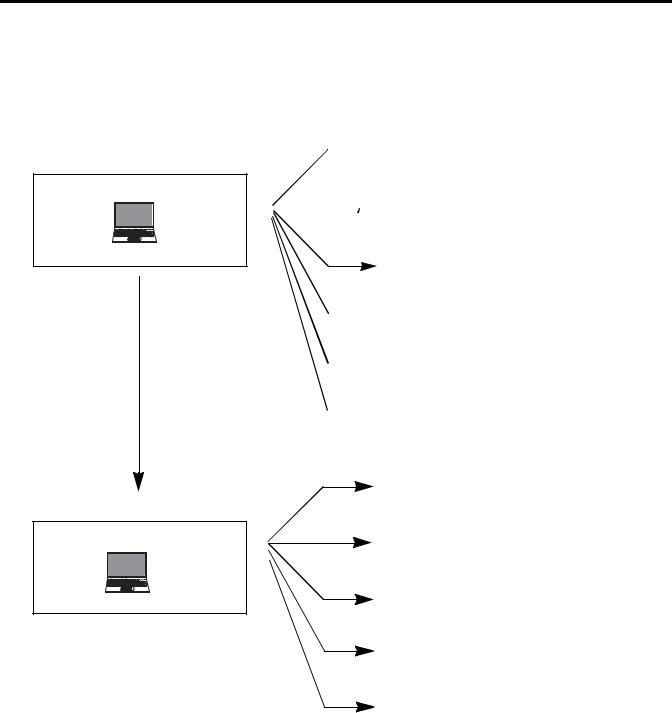
This quick start instructions illustrate how you can use the CIP Generic and CIP Symbolic Client Messaging functions on Micro830 and Micro850 controllers. It includes two sample projects that provide step-by-step instructions on how to program using the CIP messaging function blocks and assign values to the parameters to make a simple query/command from a Micro850 Controller A to a Micro850 Controller B using both messaging features.
To learn more about the MSG_CIPGeneric and MSG_CIPSymbolic function blocks and their corresponding input and output parameters, see the Connected Components Workbench Online Help and MSG_CIPSYMBOLIC Function Block on page 35 and MSG_CIPGENERIC Function Block on page 39.
Controller A
Stratix
Ethernet
Switch
Controller B
IMPORTANT To use the Micro800 CIP client messaging feature effectively, users need to have a basic understanding of the following:
•MSG_CIPGeneric and MSG_CIPSymbolic Function Blocks
See MSG_CIPSYMBOLIC Function Block on page 35 and MSG_CIPGENERIC Function Block on page 39.
•Programming and working with elements in the Connected Components Workbench software
You need to have a working knowledge of ladder diagram, structured text, or function block diagram programming to be able to work with function blocks, and input/output parameters. For tips and recommendations on programming CIP messaging instructions, see Programming Tips and Recommendations for Micro800 CIP Messaging Instructions (MSG) on page 49.
Hardware and Software Compatibility
The CIP Generic and CIP Symbolic Messaging features on Micro830 and Micro850 controllers are compatible with Connected Components Workbench revision 4 and firmware revision 4 and later.
ATTENTION: To learn more about Connected Components Workbench and detailed descriptions of the variables for the MSG Function Blocks, refer to Connected Components Workbench Online Help that comes with your Connected Components Workbench installation.
Rockwell Automation Publication 2080-QS002A-EN-E - April 2013 |
1 |
Where to Start
Follow These Steps
The major subsections for this quick start project are outlined in the following flowchart. Follow the steps under each subsection to become familiar with the required procedure to configure your controller, set up a sample project, and create programs for CIP messaging.
 Create CIP Symbolic Program (Write) on page 8
Use CIP Symbolic Client Messaging
 Configure Controller B on page 14
See page 7
 See the Results on page 15
 Create CIP Symbolic Program (Read) on page 16
 Configure Controller B on page 21
 See the Results on page 22
|
|
Create CIP Generic Message Program on page 24 |
|
Use CIP Generic Client Messaging |
Configure Controller B on page 30 |
|
|
|
|
See page 23 |
See the Results on page 30 |
|
|
Create CIP Generic Message Program: |
|
|
Single Controller on page 31 |
|
|
See the Results on page 34 |
TIP |
Download the Sample Code |
|
|
You can download the sample code for the programs used in this Quick Start from the following link: |
|
|
http://www.rockwellautomation.com/go/scmicro800 |
|
2 |
Rockwell Automation Publication 2080-QS002A-EN-E - April 2013 |

Chapter 1
Create a Micro800 Project
Introduction
In this chapter, you will create a Micro850 controller project through the Connected Components Workbench.
Before You Begin
Ensure that you have properly installed revision 4 of the Connected Components Workbench.
What You Need
•Connected Components Workbench revision 4 or later
•Firmware revision 4 and later
Rockwell Automation Publication 2080-QS002A-EN-E - April 2013 |
3 |

Chapter 1 Create a Micro800 Project
Create a Micro800 Project in Connected Components Workbench
Launch the Connected Components Workbench software.
1.On the Device Toolbox, expand the list of Controllers by clicking the + sign.
Be sure to select the catalog number that matches your Micro850 controller.
TIP
2.Select major revision 4 when manually adding a Micro850 controller.
If your controller is online, use the Discover feature to automatically discover your controller.
4 |
Rockwell Automation Publication 2080-QS002A-EN-E - April 2013 |
Create a Micro800 Project |
Chapter 1 |
|
|
3.Drag your controller onto the Project Organizer pane.
4. Go to File → Save Project As.
5.Provide a project name for your project. Click OK.
TIP |
Any Micro830/Micro850 controller can be used to follow the quickstart |
|
instructions described in this publication as long as it meets the software |
|
and firmware compatibility requirements for the Micro800 CIP |
|
Messaging feature. See Hardware and Software Compatibility on |
|
page 1. |
Rockwell Automation Publication 2080-QS002A-EN-E - April 2013 |
5 |

Chapter 1 Create a Micro800 Project
Notes:
6 |
Rockwell Automation Publication 2080-QS002A-EN-E - April 2013 |

Chapter 2
Use CIP Symbolic Client Messaging
Introduction
Micro830 and Micro850 controllers support CIP Symbolic client messaging through the MSG_CIPSYMBOLIC function block. This feature enables the sending of CIP Symbolic messages through Ethernet or serial cable.
In this chapter, you will learn how to use the function block to send a write instruction from Controller A to Controller B. Specifically, it shows you how to create a program that will write a value to Controller B’s global variable, UDINT_FromA.
Stratix
Ethernet
Switch
Controller A
Catalog: 2080-LC50-48QVB
IP Address: 192.168.1.18
Subnet Mask: 255.255.255.1
Gateway Address: 192.168.1.1
Value to write to B: 978654321
Global Variable: UDINT_FromA
Controller B
Catalog: 2080-LC50-48QBB
IP Address: 192.168.1.19
Subnet Mask: 255.255.255.
Gateway Address: 192.168.1.1
Before You Begin
Ensure that you have properly installed revision 4 of Connected Components Workbench.
What You Need
•Connected Components Workbench revision 4 or later
•Firmware revision 4 and later
Rockwell Automation Publication 2080-QS002A-EN-E - April 2013 |
7 |
Chapter 2 Use CIP Symbolic Client Messaging
Create CIP Symbolic Program (Write)
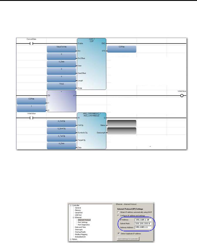
At the end of these instructions, you should have created the following program in Connected Components Workbench in your Controller A project.
RUNG 1
Use COP instruction to convert value ’ValueToWrite’ to ’A_Data’ (USINT[1...4]) which will be used in message instruction
RUNG 2
If COP instruction is successful then trigger ’WriteValue’ to coil
RUNG 3
Send message to Controller B
Build the Code
1.Open the project you created for Controller A in the last chapter through Connected Components Workbench.
2.Configure the IP address, subnet mask and gateway of Controller A as shown.
IP Address: 192.168.1.18
Subnet Mask: 255.255.255.0
Gateway Address: 192.168.1.1
8 |
Rockwell Automation Publication 2080-QS002A-EN-E - April 2013 |

Use CIP Symbolic Client Messaging |
Chapter 2 |
|
|
3.On the Project Organizer pane, right-click Programs, and then select Add New LD: Ladder Diagram.
You can press F2 to rename the program. Press Enter.
4.Right-click CIP_Sym program, and then choose Open.
5.From the Toolbox, double-click Block to add it to the rung. Alternatively, you can drag and drop Block onto the rung. Your ladder rung should appear as shown.
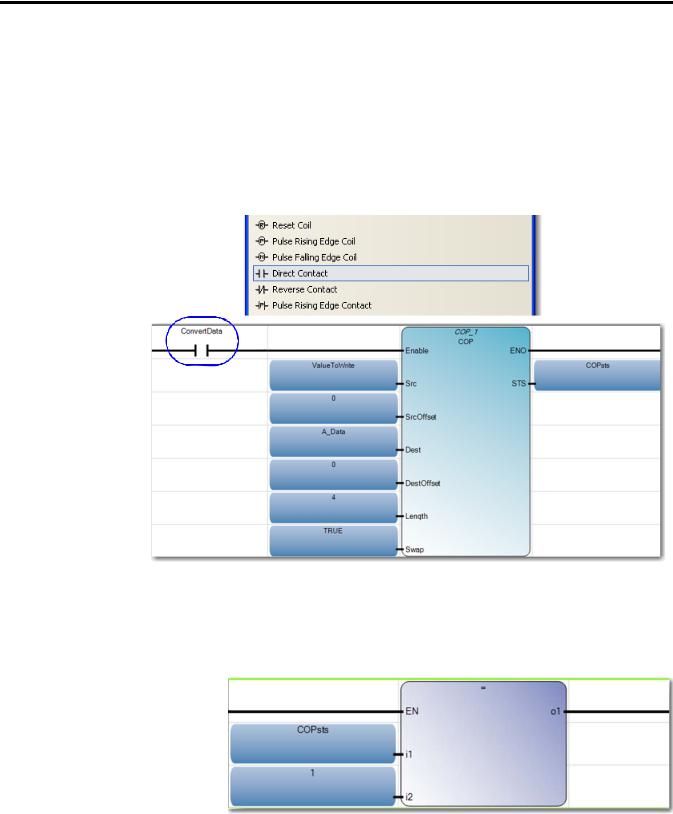
6.Add COP instruction to the rung by typing COP on the Instruction Block Selector window that appears to filter the COP function block.
7.Choose COP. Then, click OK.
8.Create variables for the COP input parameters as shown.
To learn more about the COP input and output parameter descriptions, see COP Function Block on page 43.
TIP |
You can disregard the yellow warning sign that appears. This |
|
indicates that the software expects a different data type. |
Rockwell Automation Publication 2080-QS002A-EN-E - April 2013 |
9 |
Chapter 2 Use CIP Symbolic Client Messaging
9.Add ConvertData contact to the rung by selecting Direct Contact from the Toolbox and drag it onto the rung as shown.
10.Create a second rung. From the Toolbox, select Rung and drag it onto the space just below the first rung.
11.Add = instruction block to the rung.
COP Input Parameters
Variable |
Data Type |
Dimension |
Init Value |
|
|
|
|
ValueToWrite |
DINT |
[1...1] |
987654321 |
|
|
|
|
A_Data |
USINT |
[1...4] |
|
|
|
|
|
COPsts |
UINT |
|
|
|
|
|
|
ConvertData |
BOOL |
|
|
|
|
|
|
WriteValue |
BOOL |
|
|
|
|
|
|
10 |
Rockwell Automation Publication 2080-QS002A-EN-E - April 2013 |
Use CIP Symbolic Client Messaging |
Chapter 2 |
|
|
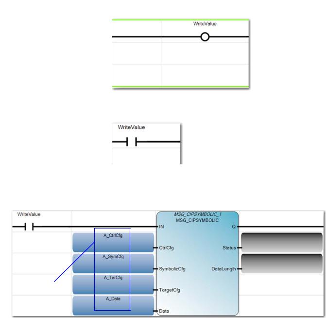
12.Add WriteValue coil to the end of the second rung by selecting Direct Coil from the Toolbox and add it to the rung as shown.
13.Create a third rung.
14.Add WriteValue contact to the rung as shown.
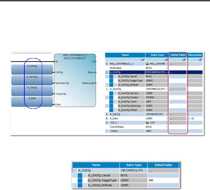
15.Add MSG_CIPSYMBOLIC function block to the rung and create the input variables as shown.
input variables
Rockwell Automation Publication 2080-QS002A-EN-E - April 2013 |
11 |
Chapter 2 Use CIP Symbolic Client Messaging
Assign Values to the MSG_CIPSYMBOLIC Input Variables
1.Set the values for the input variables through the Initial Value column of the Global Variables table.
See MSG_CIPSYMBOLIC Function Block on page 35 for more information about MSG_CIPSYMBOLIC parameters.
2.Set the value for the A_CtrlCfg input variable as shown.
See CtrlCfg on page 35 for parameter details and description.
In this example, we write the value to controller B every
300ms, and set initial value as
300.Set A_CtrlCfg.Cancel to False. By default, this parameter is set to False.
12 |
Rockwell Automation Publication 2080-QS002A-EN-E - April 2013 |

Use CIP Symbolic Client Messaging |
Chapter 2 |
|
|
3.Set the value for the A_SymCfg input variable as shown.
See SymbolicCfg on page 36 for parameter details and description.
Leave the initial value of A_SymCfg.Count at 0. The value of 1 is used for count if this value is left at the default value of 0.
4.Set the value for the A_TarCfg input variable as shown.
See TargetCfg on page 37 for parameter details and description.
Set A_TarCfg.ConnClose to False. By default, this variable is set to false.
IMPORTANT
5.Next, build and download the project to Controller A.
The value for A_Data input variable is automatically obtained from the COP instruction in rung 1.
Note that USINT is 8-bit data (whereas A UDINT is 32-bit data), so the A_Data input variable is a one-dimension array with four elements.
Rockwell Automation Publication 2080-QS002A-EN-E - April 2013 |
13 |
Loading...