


1791ES-IB16
Table of contents
 Loading...
User Manual
Guard I/O EtherNet/IP Safety Modules
Catalog Numbers 1791ES-IB8XOBV4, 1791ES-IB16
Important User Information
IMPORTANT
Solid-state equipment has operational characteristics differing from those of electromechanical equipment. Safety
Guidelines for the Application, Installation and Maintenance of Solid State Controls (publication SGI-1.1
your local Rockwell Automation sales office or online at http://www.rockwellautomation.com/literature/
important differences between solid-state equipment and hard-wired electromechanical devices. Because of this difference,
and also because of the wide variety of uses for solid-state equipment, all persons responsible for applying this equipment
must satisfy themselves that each intended application of this equipment is acceptable.
In no event will Rockwell Automation, Inc. be responsible or liable for indirect or consequential damages resulting from the
use or application of this equipment.
The examples and diagrams in this manual are included solely for illustrative purposes. Because of the many variables and
requirements associated with any particular installation, Rockwell Automation, Inc. cannot assume responsibility or
liability for actual use based on the examples and diagrams.
No patent liability is assumed by Rockwell Automation, Inc. with respect to use of information, circuits, equipment, or
software described in this manual.
Reproduction of the contents of this manual, in whole or in part, without written permission of Rockwell Automation,
Inc., is prohibited.
Throughout this manual, when necessary, we use notes to make you aware of safety considerations.
available from
) describes some
WARNING: Identifies information about practices or circumstances that can cause an explosion in a hazardous environment,
which may lead to personal injury or death, property damage, or economic loss.
ATTENTION: Identifies information about practices or circumstances that can lead to personal injury or death, property
damage, or economic loss. Attentions help you identify a hazard, avoid a hazard, and recognize the consequence.
SHOCK HAZARD: Labels may be on or inside the equipment, for example, a drive or motor, to alert people that dangerous
voltage may be present.
BURN HAZARD: Labels may be on or inside the equipment, for example, a drive or motor, to alert people that surfaces may
reach dangerous temperatures.
Identifies information that is critical for successful application and understanding of the product.
Allen-Bradley, Rockwell Software, Rockwell Automation, RSLogix, Log ix 5000, Studio 5000, Guard I/O, CompactBlock, and TechConnect are trademarks of Rockwell Automation, Inc.
Trademarks not belonging to Rockwell Automation are property of their respective companies.

New and Updated Information
Summary of Changes
Change bars (as shown in this paragraph) show the areas in this manual that are
different from previous editions and indicate the addition of revised information.
This table contains the changes made to this revision.
Top ic Pag e
Additional Resources 7
Studio 5000 Environment 7
Programming Requirements 14
Safety Data 91
Rockwell Automation Publication 1791ES-UM001D-EN-P - May 2013 3

Summary of Changes
Notes:
4 Rockwell Automation Publication 1791ES-UM001D-EN-P - May 2013

Table of Contents
Preface
About the Modules
Understand the Operation of Safety
Functions
Studio 5000 Environment . . . . . . . . . . . . . . . . . . . . . . . . . . . . . . . . . . . . . . . . . . 7
Additional Resources . . . . . . . . . . . . . . . . . . . . . . . . . . . . . . . . . . . . . . . . . . . . . . . 7
About the Specifications and Dimensions in This Manual . . . . . . . . . . . . . 8
Terminology. . . . . . . . . . . . . . . . . . . . . . . . . . . . . . . . . . . . . . . . . . . . . . . . . . . . . . . 8
Chapter 1
Before You Begin . . . . . . . . . . . . . . . . . . . . . . . . . . . . . . . . . . . . . . . . . . . . . . . . . . 9
Understand Suitability for Use . . . . . . . . . . . . . . . . . . . . . . . . . . . . . . . . . . . . 10
Follow Precautions for Use . . . . . . . . . . . . . . . . . . . . . . . . . . . . . . . . . . . . . . . 10
Precautions to Mount, Wire, and Clean. . . . . . . . . . . . . . . . . . . . . . . . . . . . 11
I/O Module Overview. . . . . . . . . . . . . . . . . . . . . . . . . . . . . . . . . . . . . . . . . . . . 12
About Catalog Numbers. . . . . . . . . . . . . . . . . . . . . . . . . . . . . . . . . . . . . . . . . . 13
Programming Requirements . . . . . . . . . . . . . . . . . . . . . . . . . . . . . . . . . . . . . . 14
About CIP Safety in EtherNet/IP Safety Architectures. . . . . . . . . . . . . . 14
Identify Major Parts of the Module . . . . . . . . . . . . . . . . . . . . . . . . . . . . . . . . 15
Chapter 2
Self-diagnostic Functions . . . . . . . . . . . . . . . . . . . . . . . . . . . . . . . . . . . . . . . . . 18
Configuration Lock . . . . . . . . . . . . . . . . . . . . . . . . . . . . . . . . . . . . . . . . . . . . . . 18
I/O Status Data. . . . . . . . . . . . . . . . . . . . . . . . . . . . . . . . . . . . . . . . . . . . . . . . . . 18
Safety Inputs. . . . . . . . . . . . . . . . . . . . . . . . . . . . . . . . . . . . . . . . . . . . . . . . . . . . . 18
Using a Test Output with a Safety Input . . . . . . . . . . . . . . . . . . . . . . . 19
Set Dual-channel Mode and Discrepancy Time . . . . . . . . . . . . . . . . . 22
Dual-channels, Equivalent . . . . . . . . . . . . . . . . . . . . . . . . . . . . . . . . . . . . 23
Dual-channels, Complementary . . . . . . . . . . . . . . . . . . . . . . . . . . . . . . . 24
Safety Input Fault Recovery. . . . . . . . . . . . . . . . . . . . . . . . . . . . . . . . . . . 26
Input Delays . . . . . . . . . . . . . . . . . . . . . . . . . . . . . . . . . . . . . . . . . . . . . . . . . 26
Safety Outputs. . . . . . . . . . . . . . . . . . . . . . . . . . . . . . . . . . . . . . . . . . . . . . . . . . . 27
Safety Output with Test Pulse . . . . . . . . . . . . . . . . . . . . . . . . . . . . . . . . . 27
Dual-channel Setting . . . . . . . . . . . . . . . . . . . . . . . . . . . . . . . . . . . . . . . . . 28
Safety Output Fault Recovery . . . . . . . . . . . . . . . . . . . . . . . . . . . . . . . . . 28
Controlling Devices . . . . . . . . . . . . . . . . . . . . . . . . . . . . . . . . . . . . . . . . . . . . . . 28
Safety Precautions. . . . . . . . . . . . . . . . . . . . . . . . . . . . . . . . . . . . . . . . . . . . . . . . 29
Legislation and Standards. . . . . . . . . . . . . . . . . . . . . . . . . . . . . . . . . . . . . . . . . 29
Europe . . . . . . . . . . . . . . . . . . . . . . . . . . . . . . . . . . . . . . . . . . . . . . . . . . . . . . 30
North America. . . . . . . . . . . . . . . . . . . . . . . . . . . . . . . . . . . . . . . . . . . . . . . 30
Japan . . . . . . . . . . . . . . . . . . . . . . . . . . . . . . . . . . . . . . . . . . . . . . . . . . . . . . . . 30
EC Directives. . . . . . . . . . . . . . . . . . . . . . . . . . . . . . . . . . . . . . . . . . . . . . . . . . . . 31
EMC Directive. . . . . . . . . . . . . . . . . . . . . . . . . . . . . . . . . . . . . . . . . . . . . . . 31
Compliance with EC Directives . . . . . . . . . . . . . . . . . . . . . . . . . . . . . . . 31
Rockwell Automation Publication 1791ES-UM001D-EN-P - May 2013 5

Table of Contents
Chapter 3
Install and Connect Your Modules
Wiring Examples
Configure the I/O Modules by Using
the Logix Designer Application
Install the Module . . . . . . . . . . . . . . . . . . . . . . . . . . . . . . . . . . . . . . . . . . . . . . . . 34
Connect the Ethernet Cable. . . . . . . . . . . . . . . . . . . . . . . . . . . . . . . . . . . . . . . 35
Set Network (IP) Address . . . . . . . . . . . . . . . . . . . . . . . . . . . . . . . . . . . . . . . . . 35
Connect I/O Power and I/O Cables . . . . . . . . . . . . . . . . . . . . . . . . . . . . . . . 36
Chapter 4
Examples of Wiring. . . . . . . . . . . . . . . . . . . . . . . . . . . . . . . . . . . . . . . . . . . . . . . 39
Chapter 5
Use Help . . . . . . . . . . . . . . . . . . . . . . . . . . . . . . . . . . . . . . . . . . . . . . . . . . . . . . . . 47
Add Modules to the I/O Configuration Tree . . . . . . . . . . . . . . . . . . . . . . . 47
Use the Module Properties and General Dialogs . . . . . . . . . . . . . . . . . . . . 49
Input Data Options. . . . . . . . . . . . . . . . . . . . . . . . . . . . . . . . . . . . . . . . . . . 50
Input Status Options . . . . . . . . . . . . . . . . . . . . . . . . . . . . . . . . . . . . . . . . . 51
Output Data Options. . . . . . . . . . . . . . . . . . . . . . . . . . . . . . . . . . . . . . . . . 53
Values and States of Tags . . . . . . . . . . . . . . . . . . . . . . . . . . . . . . . . . . . . . . 55
Work with the Safety Dialog . . . . . . . . . . . . . . . . . . . . . . . . . . . . . . . . . . . . . . 56
Configuration Ownership - Reset Ownership . . . . . . . . . . . . . . . . . . . 58
Configuration Signature . . . . . . . . . . . . . . . . . . . . . . . . . . . . . . . . . . . . . . 59
Work with the Input Configuration Dialog . . . . . . . . . . . . . . . . . . . . . . . . 60
Work with Test Output Configuration Dialog . . . . . . . . . . . . . . . . . . . . . 62
Work with the Output Configuration Dialog. . . . . . . . . . . . . . . . . . . . . . . 63
Save and Download the Module Configuration . . . . . . . . . . . . . . . . . . . . . 65
Interpret Module Indicators
Get Diagnostic Status from Modules
by Using Explicit Messaging
Safety Data
Configuration Reference Information
Index
Chapter 6
Module Indicators. . . . . . . . . . . . . . . . . . . . . . . . . . . . . . . . . . . . . . . . . . . . . . . . 67
Configuration Lock Indicator . . . . . . . . . . . . . . . . . . . . . . . . . . . . . . . . . . . . . 69
Appendix A
Work with 1791ES-IB8XOBV4 Modules . . . . . . . . . . . . . . . . . . . . . . . . . . 72
Work with 1791ES-IB16 Modules. . . . . . . . . . . . . . . . . . . . . . . . . . . . . . . . . 77
I/O Data Supported by Each Module . . . . . . . . . . . . . . . . . . . . . . . . . . . . . . 81
I/O Assembly and Reference Data . . . . . . . . . . . . . . . . . . . . . . . . . . . . . . . . . 83
Explicit Messages . . . . . . . . . . . . . . . . . . . . . . . . . . . . . . . . . . . . . . . . . . . . . . . . . 88
Appendix B
. . . . . . . . . . . . . . . . . . . . . . . . . . . . . . . . . . . . . . . . . . . . . . . . . . . . . . . . . . . . . . . . . 91
Appendix C
Understand Parameter Groups . . . . . . . . . . . . . . . . . . . . . . . . . . . . . . . . . . . . 93
6 Rockwell Automation Publication 1791ES-UM001D-EN-P - May 2013
Preface
Read and understand this manual before using the described products. Consult
your Rockwell Automation representative if you have any questions or
comments. This manual describes how to use Guard I/O modules.
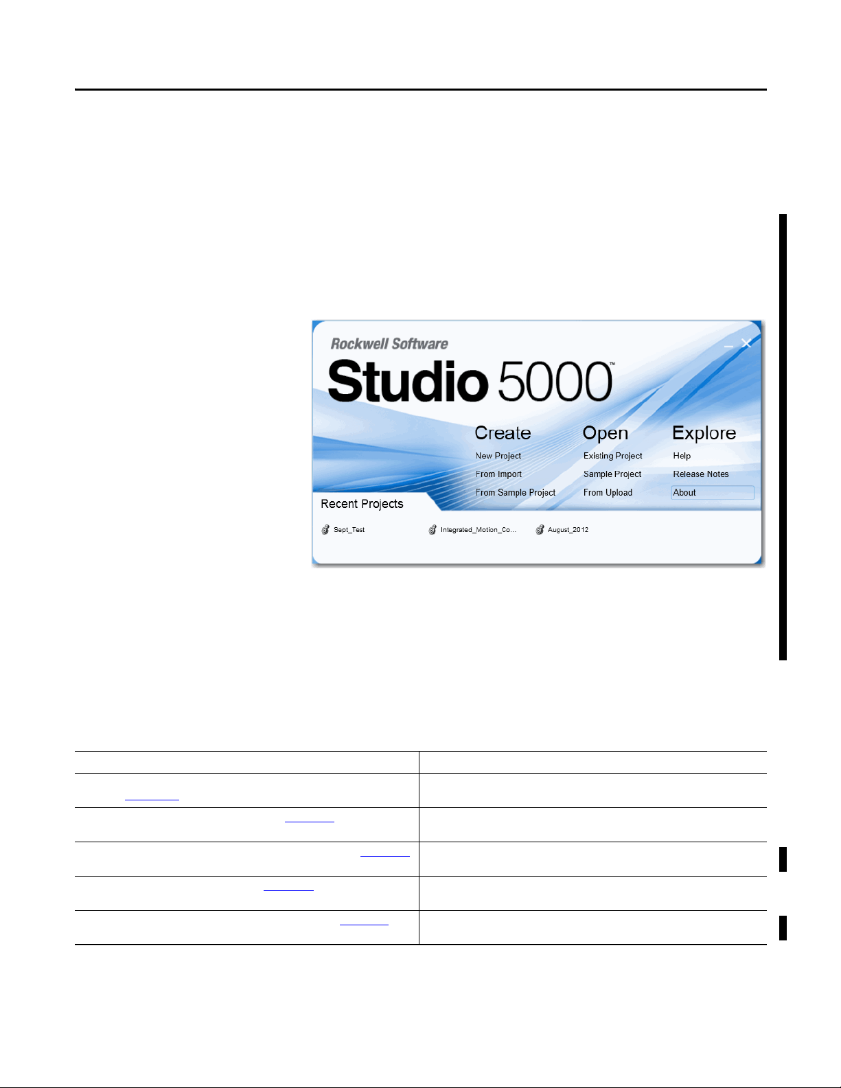
Studio 5000 Environment
The Studio 5000™ Engineering and Design Environment combines engineering
and design elements into a common environment. The first element in the Studio
5000 environment is the Logix Designer application. The Logix Designer
application is the rebranding of RSLogix™ 5000 software and will continue to be
the product to program Logix5000™ controllers for discrete, process, batch,
motion, safety, and drive-based solutions.
The Studio 5000 environment is the foundation for the future of Rockwell
Automation® engineering design tools and capabilities. This environment is the
one place for design engineers to develop all of the elements of their control
system.
Additional Resources
Refer to the following as needed for additional help when setting up and using
your modules. For specifications, refer to the relevant installation instructions.
Resource Description
CompactBlock Guard I/O EtherNet/IP Safety Modules Installation Instructions,
publication 1791ES-IN001
GuardLogix 5570 Controllers User Manual, publication 1756-UM022
GuardLogix 5570 Controller Systems Safety Reference Manual, publication 1756-RM099
GuardLogix Controllers User Manual, publication 1756-UM020 Provides information on how to install, configure, program, and use GuardLogix 5560 and
GuardLogix Controller Systems Safety Reference Manual, publication 1756-RM093
Rockwell Automation Publication 1791ES-UM001D-EN-P - May 2013 7
Provides detailed specifications and information related to installation of Guard I/O
modules.
Provides information on how to install, configure, program, and use GuardLogix 5570
controllers in Studio 5000 Logix Designer projects.
Provides information on safety application requirements for GuardLogix 5570 controllers
in Studio 5000 Logix Designer projects.
5570 controllers in RSLogix 5000 projects.
Provides information on safety application requirements for GuardLogix 5560 and 5570
controllers in RSLogix 5000 projects.

Preface
Resource Description
GuardLogix Safety Application Instructions Safety Reference Manual, publication
1756-RM095
Ethernet Design Considerations Reference Manual, publication ENET-RM002 Describes the required media components and how to plan for and install these required
ODVA Media Planning and Installation Manual, publication 00148-BR00
the EtherNet/IP Library at ODVA.org
, available from
Provides reference information describing the GuardLogix Safety Application Instruction
Set.
components.
Describes the required media components and how to plan for and install these required
components.
You can view or download publications at
http://www.rockwellautomation.com/literature/
. To order paper copies of
technical documentation, contact your local Allen-Bradley distributor or
Rockwell Automation sales representative.
About the Specifications and Dimensions in This Manual
Product specifications and accessories can change at any time based on
improvements and other reasons. Consult with your Rockwell Automation
representative to confirm actual specifications of purchased product. Dimensions
and weights are nominal and are not for use for manufacturing purposes, even
when tolerances are shown.
Terminology
Term Definition
Connection Logical communication channel for communication between nodes. Connections are maintained and controlled between masters and slaves.
EDS Acronym for electronic data sheet, a template that RSNetWorx software uses to display the configuration parameters, I/O data profile, and connection-type
support for a given I/O module. These are simple tex t files used by RSNetWorx software for you to identify products and commission them on a network.
L- Output +24V DC common.
M Sinking output common channel, output switches to the common voltage.
MTBF Acronym for mean time between failure, the average time between failure occurrences.
ODVA Acronym for Open DeviceNet Vendor Association, a nonprofit association of vendors established for the promotion of CIP networks.
P Sourcing output channel, output switches to the plus voltage.
PFD Acronym for probability of failure on demand, the average probability of a system to fail to perform its design function on demand.
PFH Acronym for probability of failure per hour, the probability of a system to have a dangerous failure occur per hour.
Proof test Periodic test per formed to detect failures in a safety-related system so that, if necessary, the system can be restored to an as-new condition or as close as
practical to this condition.
S+ Output +24V DC.
SNN Acronym for safety network number, which uniquely identifies a network across all networks in the safety system. You are responsible for assigning a
unique number for each safety network or safety sub-net within a system.
Standard Devices or portions of devices that do not par ticipate in the safety function.
Refer to the table for the meaning of common terms.
8 Rockwell Automation Publication 1791ES-UM001D-EN-P - May 2013

About the Modules
Top ic Pa ge
Before You Begin 9
Understand Suitability for Use 10
Follow Precautions for Use 10
Precautions to Mount, Wire, and Clean 11
I/O Module Overview 12
About Catalog Numbers 13
Programming Requirements 14
About CIP Safety in EtherNet/IP Safety Architectures 14
Identify Major Parts of the Module 14
Chapter 1
Before You Begin
This chapter includes important overview information and precautions for use of
the Guard I/O modules that implement the EtherNet/IP safety protocol. Also
included is an overview on how these I/O modules are used within a safety
system.
Always observe the following when using a module, noting that in this manual we
use safety administrator to mean a person qualified, authorized, and responsible
to secure safety in the design, installation, operation, maintenance, and disposal
of the machine.
• Thoroughly read and understand this manual before installing and
operating the module.
• Keep this manual in a safe place where personnel can refer to it when
necessary.
• Use the module properly according to the installation environment,
performance, and functions of the machine.
• Verify that a safety administrator conducts a risk assessment on the
machine and determines module suitability before installation.
Verify for CE LVD compliance, the external power supply that provides power to
the modules is safety extra-low voltage (SELV) rated. Some Rockwell
Automation Bulletin 1606 power supplies are SELV-compliant. Verify Bulletin
1606 Installation Instructions.
Rockwell Automation Publication 1791ES-UM001D-EN-P - May 2013 9
Chapter 1 About the Modules
Verify that the Guard I/O firmware version is correct prior to commissioning the
safety system, noting that firmware information related to safety controllers is
available at:
http://www.rockwellautomation.com/products/certification/
Understand Suitability for Use
Follow Precautions for Use
Rockwell Automation is not responsible for conformity with any standards,
codes, or regulations that apply to the combination of the products in your
application or use of the product.
Take all necessary steps to determine the suitability of the product for the
systems, machine, and equipment with which it is used.
Know and observe all prohibitions of use applicable to this product.
Never use the products for an application involving serious risk to life or property
without making sure that the system as a whole was designed to address the risks
and that the Rockwell Automation product is properly rated and installed for the
intended use within the overall equipment or system.
ATT EN TI ON :
• Safety state of the inputs and outputs is defined as the off state.
• Safety state of the module and its data is defined as the off state.
• Use the Guard I/O module only in applications where the off state is the safety
state.
• Serious injury can occur due to breakdown of safety outputs. Do not connect
loads beyond the rated value to the safety outputs.
• Serious injury can occur due to loss of required safety functions. Wire the
module properly so that supplyy voltages or voltages for loads do not touch
the safety outputs accidentally or inadvertently.
10 Rockwell Automation Publication 1791ES-UM001D-EN-P - May 2013

About the Modules Chapter 1
ATTENTION: Use a DC power supply satisfying the following
requirements to prevent electric shock:
• A DC power sup ply wi th dou ble or reinforced i nsulatio n, for examp le,
according to IED/EN 60950 or EN 50178 or a transformer according to
IEC/EN 61558
• A DC supply satisfies requirement for class 2 circuits or limited
voltage/current circuit stated in UL 508
• Use an external power supply that is safety extra-low voltage (SELV)
rated
• Follow these precautions for safe use.
• Wire conductors correctly and verify operation of the module before
placing the system into operation. Incorrect wiring can lead to loss of
safety function.
• Do not apply DC voltages exceeding the rated voltages to the
module.
• Apply properly specified voltages to the module inputs. Applying
inappropriate voltages causes the module to fail to perform its
specified function, which leads to loss of safety functions or damage
to the module.
• Never use test outputs as safety outputs. Test outputs are not safety
outputs.
• Note that after installation of the module, a safety administrator
must confirm the installation and conduct trial operation and
maintenance.
• Do not disassemble, repair, or modify the module. This can result in
loss of safety functions.
• Use only appropriate components or devices complying with
relevant safety standards corresponding to the required safety
category and safety integrity level.
- Conformity to requirements of the safety category and safety
integrity level must be determined for the entire system.
- We recommend you consult a certification body regarding
assessment of conformity to the required safety integrity level or
safety category.
• Note that you must confirm compliance with the applicable
standards for the entire system.
• Disconnect the module from the power supply before wiring.
Devices connected to the module can operate unexpectedly if wiring
is performed while power is supplied.
Precautions to Mount, Wire, and Clean
Observe these precautions to prevent operation failure, malfunctions, or
undesirable effects on product performance.
Follow these precautions when mounting modules.
• Use DIN rail that is 35 mm (1.38 in.) wide to mount the module into the
control panel.
• Mount modules to DIN rail securely.
• Leave at least 15 mm (0.6 in.) around the module to allow adequate
ventilation and room for wiring.
Rockwell Automation Publication 1791ES-UM001D-EN-P - May 2013 11

Chapter 1 About the Modules
Follow these instructions when wiring modules.
• Do not place communication lines and I/O lines in the same wiring duct
or track as high voltage lines.
• Wire correctly after confirming the signal names of all terminals.
• Follow torquing specifications as indicated in the installation instructions.
When cleaning modules, do not use the following:
• Thinner
• Benzene
• Acetone
I/O Module Overview
The Guard I/O modules implement the CIP-safety protocol extensions over
EtherNet/IP networks and provide various features for a safety system.
Use the modules to construct a safety-control network system that meets the
requirements up to Safety Integrity Level 3 (SIL 3) as defined in IEC 61508,
Functional Safety of Electrical, Electronic, and Programmable Electronic
Safety-related Systems, and the requirements for Safety Category 4 of the
EN 954-1 standard, Safety of machinery - Safety related parts of control systems.
Remote I/O communication for safety I/O data are performed through safety
connections supporting CIP safety over an EtherNet/IP network, and data
processing is performed in the safety controller.
The status and fault diagnostics of the I/O modules are monitored by a safety
controller through a safety connection by using a new or existing EtherNet/IP
network.
12 Rockwell Automation Publication 1791ES-UM001D-EN-P - May 2013

About the Modules Chapter 1
The following is a list of features common to Guard I/O modules:
• CIP-safety and EtherNet/IP protocol conformance
• Safety inputs
– Safety devices, such as emergency stop push buttons, gate switches, and
safety light curtains, can be connected.
– Dual-channel mode evaluates consistency between two input signals
(channels), which allows use of the module for Safety Category 3 and 4.
– The time of a logical discrepancy between two channels can be
monitored by using a discrepancy time setting.
– An external wiring short-circuit check is possible when inputs are wired
in combination with test outputs.
– Independently adjustable on and off delay is available per channel.
• Te st ou tp u ts
– Separate test outputs are provided for short circuit detection of a safety
input (or inputs).
– Power (24V) can be supplied to devices, such as safety sensors.
– Test outputs can be configured as standard outputs.
– All Guard I/O modules have numerous test outputs, of which some can
be used for broken wire detection of a muting lamp.
• Safety outputs
– Dual-channel mode evaluates consistency between two output signals
(channels).
– Safety outputs can be pulse tested to detect field wiring shorts to
24V DC and 0V DC.
• I/O status data - In addition to I/O data, the module includes status data
for monitoring I/O circuits.
• Removable I/O connectors - I/O connectors support mechanical keying.
About Catalog Numbers
Catalog Number Description Enclosure Type
1791ES-IB16 Safety input module Meets IP20 16 16 —
1791ES-IB8XOBV4 Safety I/O module with solid state outputs 8 8 4 bipolar pairs
(1) Broken wires can be detected on the muting outputs.
See the table for a listing of the types of Guard I/O modules.
Rating
Safety Inputs Test Outputs
Rockwell Automation Publication 1791ES-UM001D-EN-P - May 2013 13
(1)
Safety Outputs
Solid State
Chapter 1 About the Modules
EtherNet/IP Network
ControlNet Network
DeviceNet Network
DeviceNet
Network
EtherNet
EtherNet
RSLogix Software
RSView Software
Control Net
Network
DeviceNet Network
DeviceNet
Network
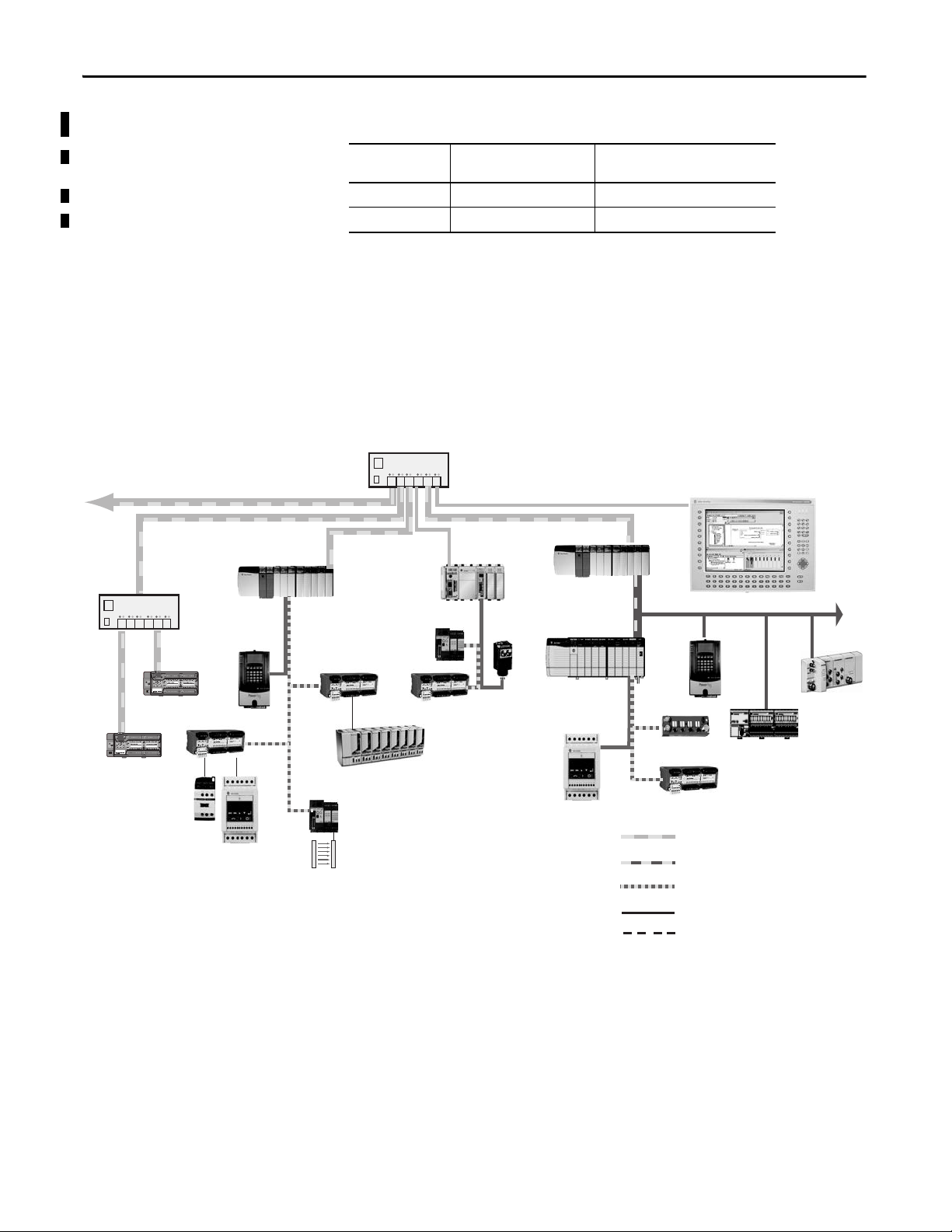
Standard Communication
Safety Communication
Programming Requirements Use the minimum software versions listed here.
Cat. No. Studio 5000 Environment
1791ES-IB16 21 16
1791ES-IB8XOBV4 21 16
(1) This version or later.
Versio n
(1)
RSLogix 5000 Software Version
(EtherNet/IP Network)
(1)
About CIP Safety in EtherNet/IP Safety Architectures
Use Guard I/O modules in EtherNet/IP safety architectures as shown in the
figure. The Guard I/O family is a set of I/O modules that when connected to an
EtherNet/IP safety network are suitable for applications up to SIL3, as defined in
the IEC 61508 standard, and Safety Category 4, as defined in the EN 954-1
standard.
Figure 1 - Safety Interlocking and Control via CIP Safety
Safety controllers control the safety outputs. Safety or standard controllers can
control the standard outputs.
Identify Major Parts of the Module
14 Rockwell Automation Publication 1791ES-UM001D-EN-P - May 2013
See the figure for module identification. For pin-out information, refer to the
relevant installation instructions.
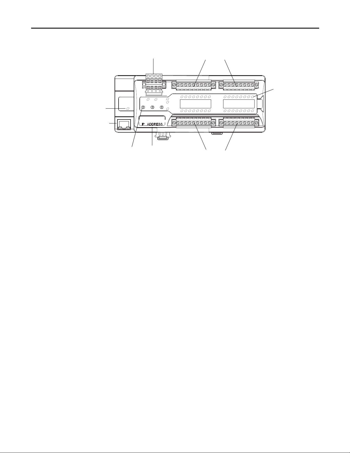
Figure 2 - Major Module Parts
I/O Connectors
I/O Connectors
Power Connector
LED Status
Indicators
IP Address
Switch
EtherNet IP Address
Label
EtherNet
Connecto r
Network
Activity
Indicator
About the Modules Chapter 1
Rockwell Automation Publication 1791ES-UM001D-EN-P - May 2013 15

Chapter 1 About the Modules
Notes:
16 Rockwell Automation Publication 1791ES-UM001D-EN-P - May 2013
Chapter 2
Output Off
Input
Inputs to Network Off
EtherNet/IP Network
Safety
Status
44076
Understand the Operation of Safety Functions
Top ic Pa ge
Self-diagnostic Functions 18
Configuration Lock 18
I/O Status Data 18
Safety Inputs 18
Safety Outputs 27
Controlling D evices 28
Safety Precautions 29
Legislation and Standards 29
EC Directives 31
Read this chapter for information related to the safety functions of the modules.
Also included is a brief overview on international standards and directives that
you must be familiar with.
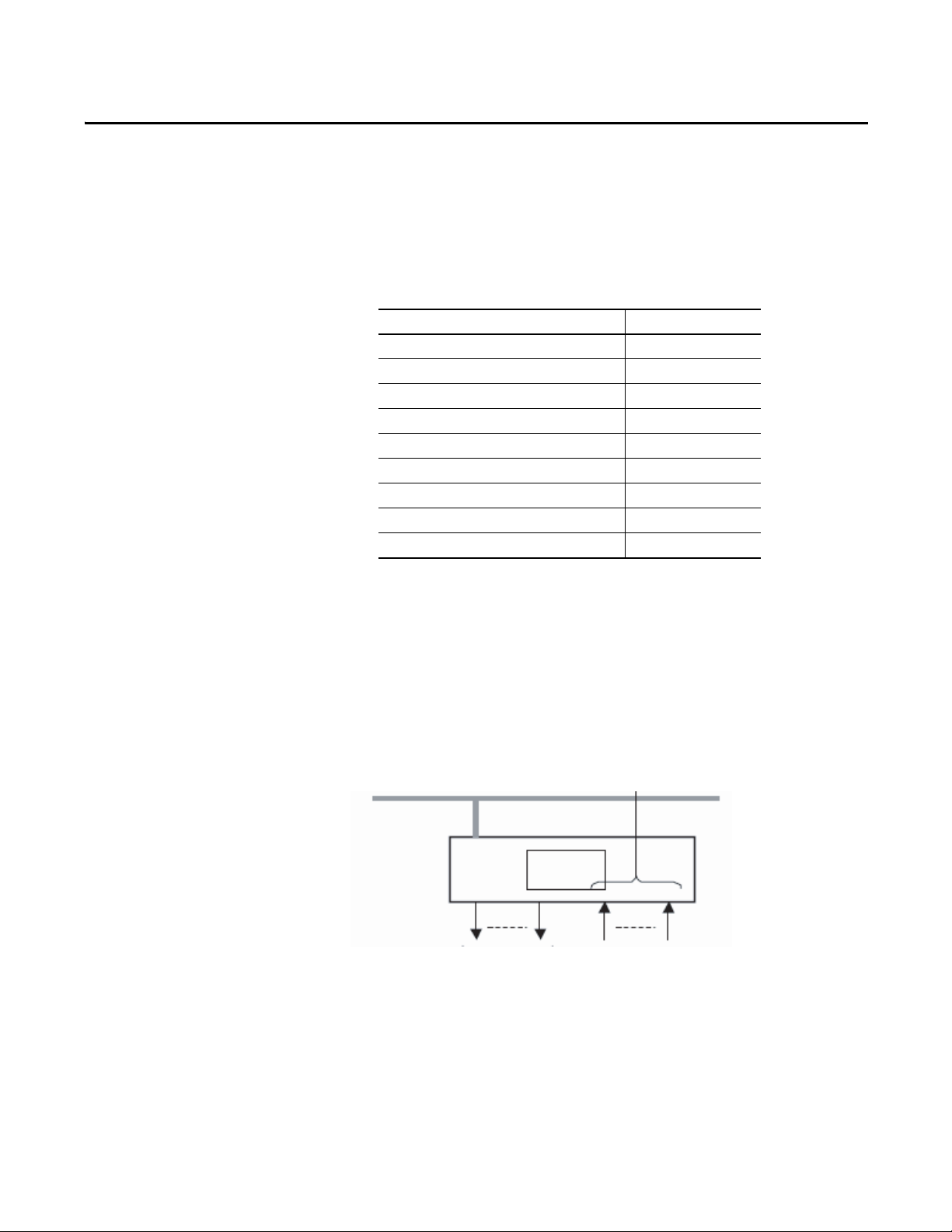
The following status is the safety state of the Guard I/O modules:
• Safety outputs: off
• Safety input data to network: off
Figure 3 - Safety Status
The module is designed for use in applications where the safety state is the off
state.
Rockwell Automation Publication 1791ES-UM001D-EN-P - May 2013 17

Chapter 2 Understand the Operation of Safety Functions
Self-diagnostic Functions
Configuration Lock
I/O Status Data
Self-diagnostics are performed when the power is turned on and periodically
during operation. If a fatal internal module error occurs, the red module status
(MS) indicator is illuminated, and the safety outputs and input data and status to
the network turn off.
After configuration data has been downloaded and verified, the configuration
data within the module can be protected.
For GuardLogix systems, the LED indicator is not used. Reference information
about safety signatures in the GuardLogix Controller Systems Safety Reference
Manual, publication 1756-RM093
In addition to I/O data, the module provides status data for monitoring the I/O
circuits. The status data includes the following data, which can be read by the
controllers. Note that 1 = ON/Normal and 0 = OFF/Fault/Alarm.
• Individual Point Input Status
• Combined Input Status
• Individual Point Output Status
• Combined Output Status
• Individual Test Output Status
• Individual Output Readback (actual ON/OFF state of the outputs)
.
Safety Inputs
Status data indicate whether each safety input, safety output, or test output is
normal (normal status: ON, faulted status: OFF). For fatal errors,
communication connections can be broken, so the status data cannot be read.
Combined status is provided by an AND of the status of all safety inputs or all
safety outputs. When all inputs or outputs are normal the respective combined
status is ON. When one or more of them has an error the respective combined
status is OFF. This is known as the combined safety input status or combined
safety output status.
Read this section for information about safety inputs and their associated test
outputs. A safety input can be used with test outputs. Safety inputs are used to
monitor safety input devices.
18 Rockwell Automation Publication 1791ES-UM001D-EN-P - May 2013
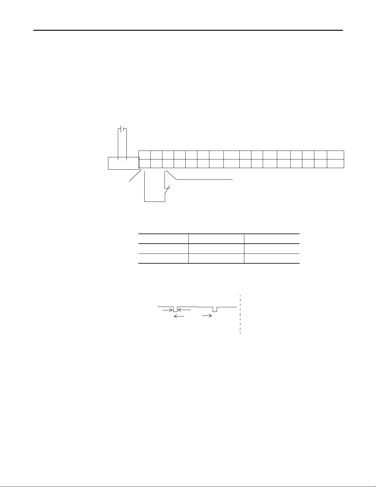
Using a Test Output with a Safety Input
I8 I9 T8 T9 I10 I11 T10 T11M I12 I13 T12 T13 I14 I15 T14 T15M
I0 I1 T0 T1 I2 I3 T2 T3M I4 I5 T4 T5 I6 I7 T6 T7M
IN+ IN-
24V DC
24V DC Output with Test Pulse
External Contact
Safety Input
44295
OUT
On
Off
Typ ic al
500 μs
Typ ic al
150 ms
A test output can be used in combination with a safety input for short circuit
detection. Configure the test output as a pulse test source and associate it to a
specific safety input.
The test output can also be used as a power supply to source 24V DC for an
external input circuit.
Figure 4 - Example Use of a 1791ES-IB16 Module
Understand the Operation of Safety Functions Chapter 2
Table 1 - Typical Pulse Width and Period
Attribute 1791ES-IB8XOBV4 1791ES-IB16
Pulse width 500 μs 500 μs
Period 150 ms 150 ms
Figure 5 - Test Pulse in a Cycle
Rockwell Automation Publication 1791ES-UM001D-EN-P - May 2013 19
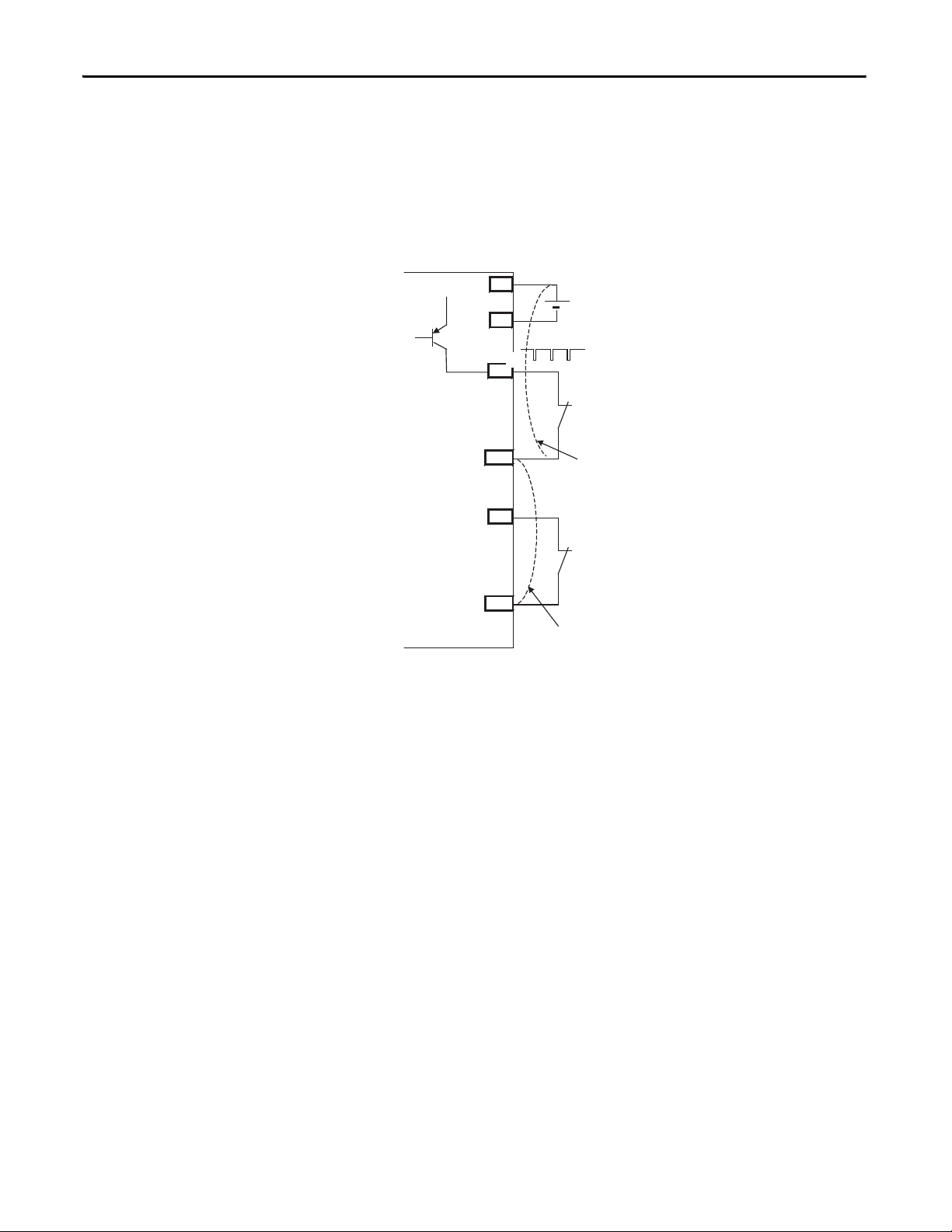
Chapter 2 Understand the Operation of Safety Functions
T0
IN0
T1
IN1
IN+
IN-
External
Short-circuit Between Input Signal Lines and Power
Supply (Positive Side)
External Contact
Short-circuit Between Input Signal Lines
44079
When the external input contact is closed, a test pulse is output from the test
output terminal to diagnose the field wiring and input circuitry. By using this
function, short-circuits between input signal lines and the power supply (positive
side), and short-circuits between input signal lines can be detected.
Figure 6 - Short-circuit Between Input Signal Lines
24V
24V
0V
20 Rockwell Automation Publication 1791ES-UM001D-EN-P - May 2013

Understand the Operation of Safety Functions Chapter 2
24V
0V
T0
Input Terminal 0
External Device
Faul t De tected
Remote
I/O
Data
ON
OFF
ON
OFF
ON
OFF
ON
OFF
24V
0V
ON
OFF
T0
Safety Input
Status 0
Fault Detection
Remote
I/O
Data
ON
OFF
ON
OFF
ON
OFF
Safety Input
Status 0
Safety Input 0
Safety Input 0
Input Terminal 0
Normal Operation
External Device
If an error is detected, safety input data and safety input status turns off.
Figure 7 - Normal Operation and Fault Detection (not to scale)
Rockwell Automation Publication 1791ES-UM001D-EN-P - May 2013 21

Chapter 2 Understand the Operation of Safety Functions
IMPORTANT
IMPORTANT
Set Dual-channel Mode and Discrepancy Time
To support redundant channel safety devices, the consistency between signals on
two channels can be evaluated. Either equivalent or complementary can be
selected. This function monitors the time during which there is a discrepancy
between the two channels.
If the length of the discrepancy exceeds the configured discrepancy time
(0…65,530 ms in increments of 10 ms), the safety input data and the
individual-safety input status turns off for both channels.
The dual-channel function is used with two consecutive inputs that are
paired together, starting at an even input number, such as inputs 0 and 1, 2
and 3, and so on.
Do not set the discrepancy time longer than necessary. The purpose of the
discrepancy time is to allow for normal differences between contact
switching when demands are placed on safety inputs. For this testing to
operate correctly, only a single demand on the safety input is expected
during the discrepancy time. If the discrepancy time is set too high, and
multiple demands occur during this time, then both safety input channels
will fault.
22 Rockwell Automation Publication 1791ES-UM001D-EN-P - May 2013
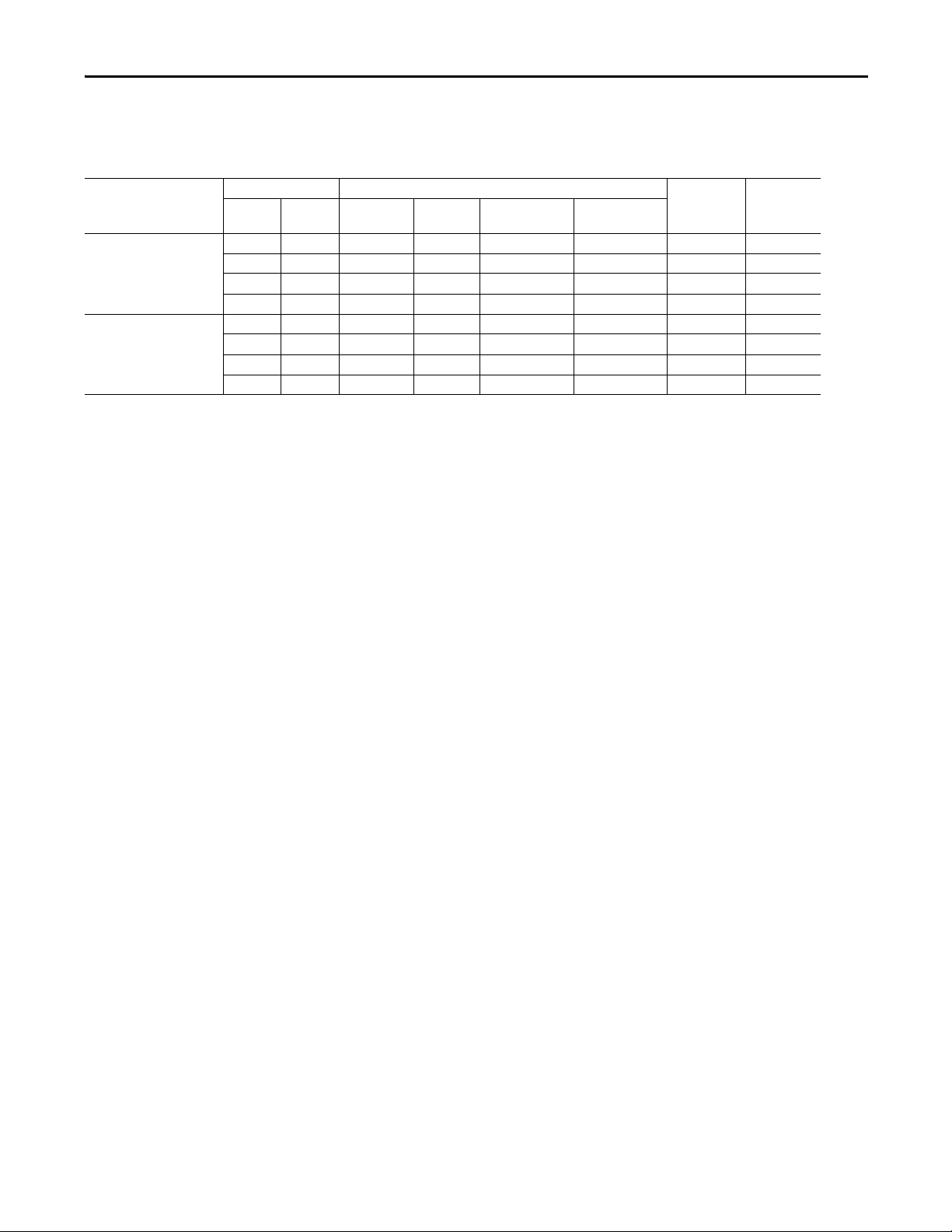
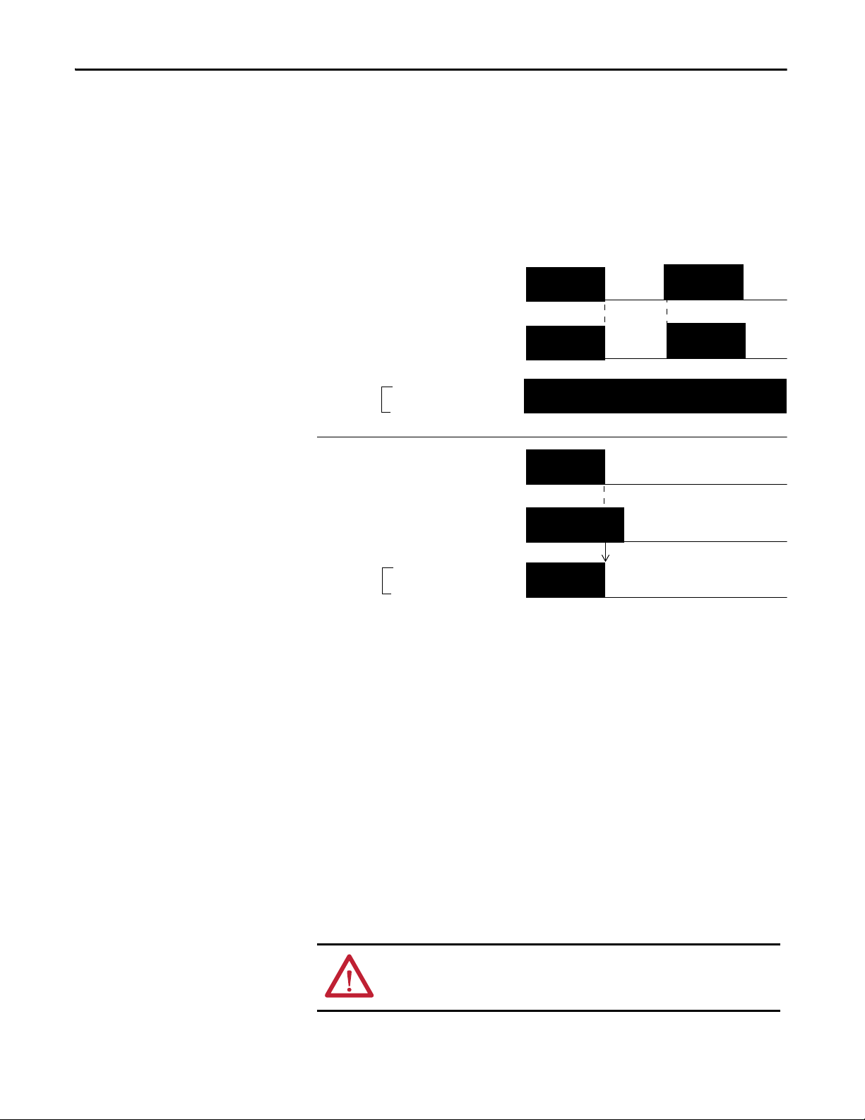
The following table shows the relation between input terminal states and
controller input data and status.
Table 2 - Terminal Input Status and Controller I/O Data
Understand the Operation of Safety Functions Chapter 2
Dual-channel Mode Input Terminal Controller Input Data and Status Dual- channel
IN0 IN1 Safety
Dual-channels, Equivalent OFF OFF OFF OFF ON ON OFF Normal
OFF ON OFF OFF OFF OFF OFF Fault
ON OFF OFF OFF OFF OFF OFF Fault
ON ON ON ON ON ON ON Normal
Dual-channels,
Complementary
OFF OFF OFF ON OFF OFF OFF Fault
OFF ON OFF ON ON ON OFF Normal
ON OFF ON OFF ON ON ON Normal
ON ON OFF ON OFF OFF OFF Fault
Input 0 Data
Safety
Input 1 Data
Safety
Input 0 Status
Safety
Input 1 Status
Resultant
Data
Dual-channel
Resultant
Status
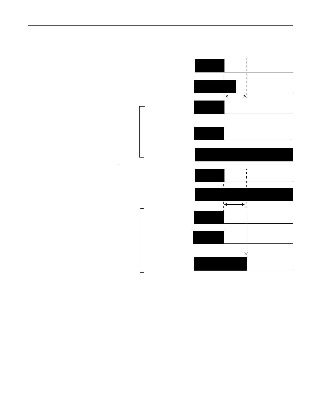
Dual-channels, Equivalent
In Equivalent mode, both inputs of a pair must typically be in the same
(equivalent) state. When a transition occurs in one channel of the pair, prior to
the transition of the second channel of the pair, a discrepancy occurs. If the
second channel transitions to the appropriate state prior to the discrepancy time
elapsing, the inputs are considered equivalent. If the second transition does not
occur before the discrepancy time elapses, the channels will fault. In the fault state
the input and status for both channels are set low (off). When configured as an
equivalent dual pair, the data bits for both channels will always be sent to the
controller as equivalent, both high or both low.
Rockwell Automation Publication 1791ES-UM001D-EN-P - May 2013 23
Chapter 2 Understand the Operation of Safety Functions
ON
OFF
IN0
Safety Input 0
IN1
Fault Detec ted
Discrepancy Time
Remote
I/O
Data
ON
OFF
ON
OFF
ON
OFF
ON
OFF
ON
OFF
ON
OFF
IN0
Safety Input
Status 0, 1
IN1
Fault Detection
Remote
I/O
Data
ON
OFF
ON
OFF
ON
OFF
Discrepancy Time
Safety Input
Status 0, 1
Safety Input 1
Safety Input 1
Safety Input 0
Normal Operation
Figure 8 - Equivalent, Normal Operation and Fault Detection (not to scale)
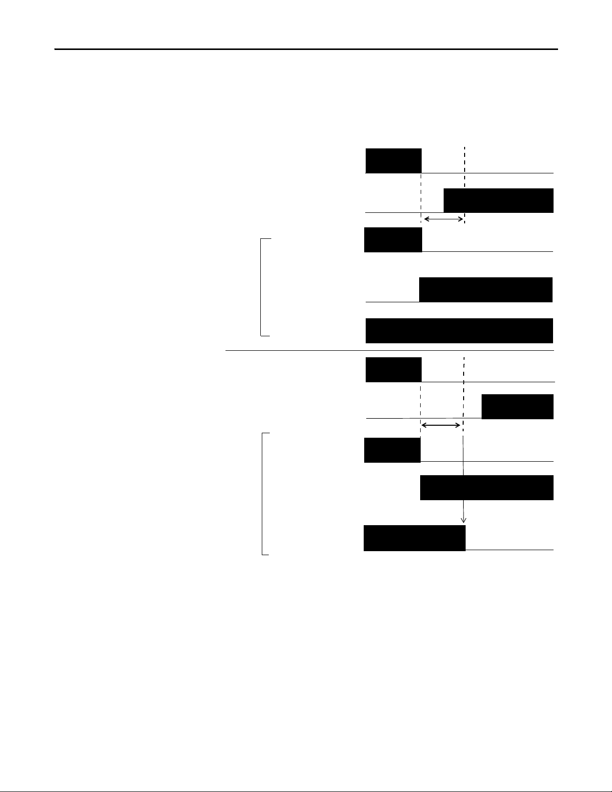
Dual-channels, Complementary
In Complementary mode, the inputs of a pair must typically be in the opposite
(complementary) state. When a transition occurs in one channel of the pair prior
to the transition of the second channel of the pair, a discrepancy occurs. If the
second channel transitions to the appropriate state prior to the discrepancy time
elapsing, the inputs are considered complementary.
If the second transition does not occur before the discrepancy time elapses, the
channels will fault. The fault state of complementary inputs is the even numbered
input turned off and the odd numbered input turned on. Note that if faulted,
24 Rockwell Automation Publication 1791ES-UM001D-EN-P - May 2013
Understand the Operation of Safety Functions Chapter 2
ON
OFF
IN0
Safety Input 0
IN1
Faul t De tected
Discrepancy Time
Remote
I/O
Data
ON
OFF
ON
OFF
ON
OFF
ON
OFF
ON
OFF
ON
OFF
IN0
Safety Input
Status 0, 1
IN1
Fault Detection
Remote
I/O
Data
ON
OFF
ON
OFF
ON
OFF
Discrepancy Time
Safety Input
Status 0, 1
Safety Input 1
Safety Input 1
Safety Input 0
Normal
Operation
both channel status bits are set low. When configured as a complementary dual
channel pair, the data bits for both channels will always be sent to the controller
in complementary, or opposite states.
Figure 9 - Complementary, Normal Operation and Fault Detection (not to scale)
Rockwell Automation Publication 1791ES-UM001D-EN-P - May 2013 25

Chapter 2 Understand the Operation of Safety Functions
44094
On-delay
ON
OFF
ON
OFF
Input Signal
Remote I/O
Data Safety
Input
44094
44095
Remote I/O Data
Safety Input
Off-delay
Input Signal
ON
OFF
ON
OFF
Safety Input Fault Recovery
If an error is detected, the safety input data remains in the off state. The
procedure for activating the safety input data again is as follows.
1. Remove the cause of the error.
2. Place the safety input (or safety inputs) into the safety state.
The safety input status turns on (fault cleared) after the input-error latch
time has elapsed. The I/O indicator (red) turns off. The input data can
now be controlled.
Input Delays
On-delay - An input signal is treated as logic 0 during the on-delay time (0…126
ms, in increments of 6 ms) after the input contact’s rising edge. The input only
turns on if the input contact remains on after the on-delay time has elapsed. This
helps prevent rapid changes of the input data due to contact bounce.
Figure 10 - On-delay
Input
ON
OFF
ON
OFF
ON-delay
Input Signal
Remote I/O
Data Safety
Off-delay - An input signal is treated as logic 1 during the off-delay time (0…126
ms, in increments of 6 ms) after the input contact’s falling edge. The input only
turns off if the input contact remains off after the off delay time has elapsed. This
helps prevent rapid changes of the input data due to contact bounce.
Figure 11 - Off-delay
Input Signal
Remote I/O Data
Safety Input
OFF
ON
OFF
OFF-delay
26 Rockwell Automation Publication 1791ES-UM001D-EN-P - May 2013
Understand the Operation of Safety Functions Chapter 2
IMPORTANT
44096
OUT
On
Off
Typ ic al
700 μs
Typ ic al
600 ms
Safety Outputs
Read this section for information about safety outputs.
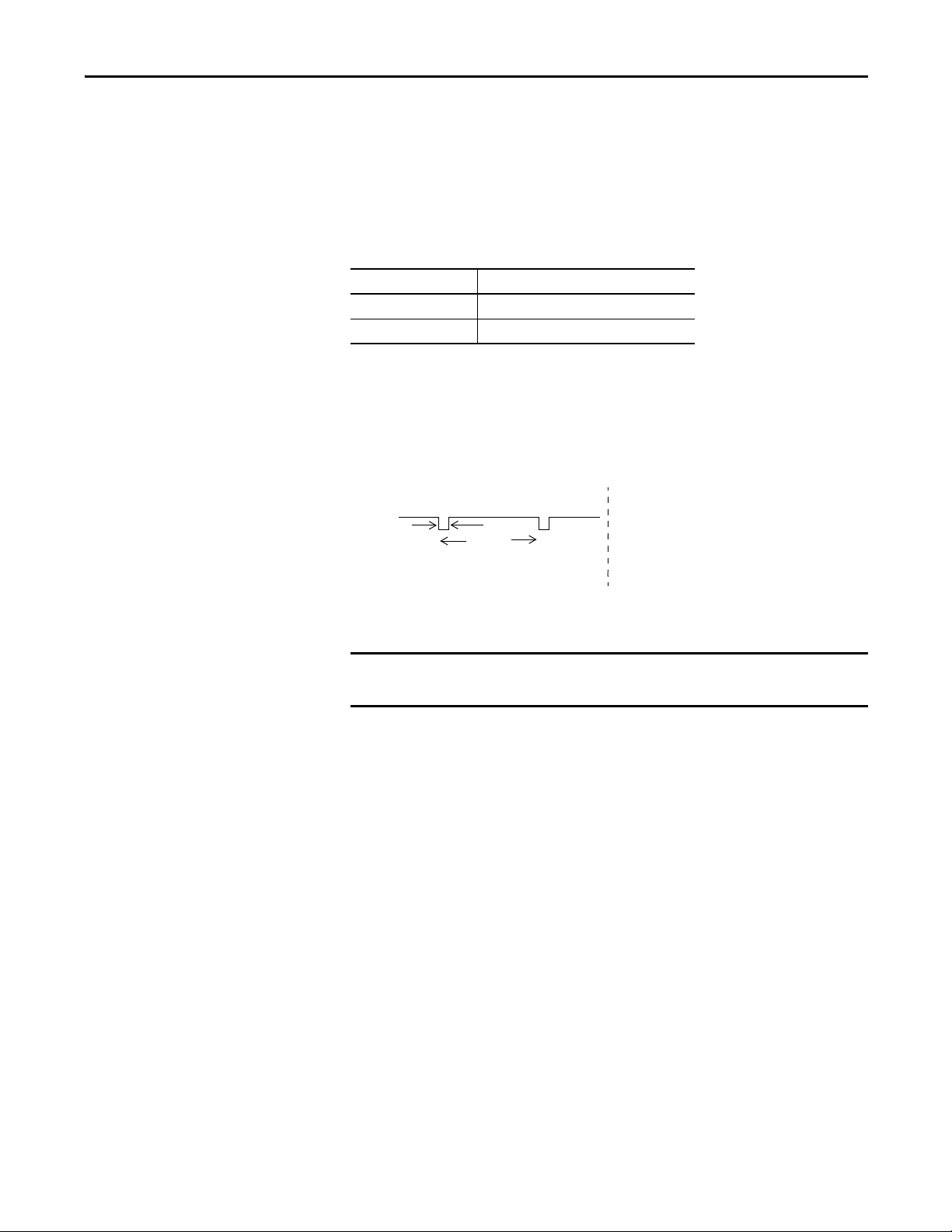
Safety Output with Test Pulse
When the safety output is on, the safety output can be test pulsed, as shown in
the figure and table.
Attribute 1791ES-IB8XOBV4
Pulse width 700 μs
Period 600 ms
By using this function, short-circuits between output signal lines and the power
supply (positive side) and short-circuits between output signal lines can be
detected. If an error is detected, the safety output data and individual-safety
output status turns off.
Figure 12 - Test Pulse in a Cycle
To prevent the test pulse from causing the connected device to
malfunction, pay careful attention to the input response time of the device.
Rockwell Automation Publication 1791ES-UM001D-EN-P - May 2013 27
Chapter 2 Understand the Operation of Safety Functions
ON
OFF
OUT0
Safety Output
Status 0, 1
OUT0
OUT1
OUT1
Safety Output
Status 0, 1
Fault Detection
Error
Detected
Remote
I/O
Data
Remote
I/O
Data
ON
OFF
ON
OFF
ON
OFF
ON
OFF
ON
OFF
Normal Oper ation
Dual-channel Setting
When the data of both channels is in the on state, and neither channel has a fault,
the outputs are turned on. The status is normal. If a fault is detected on one
channel, the safety output data and individual safety output status turn off for
both channels.
Figure 13 - Dual-channel Setting (not to scale)
Safety Output Fault Recovery
If a fault is detected, the safety outputs are switched off and remain in the off
state. The procedure for activating the safety output data again is as follows.
Controlling Devices
28 Rockwell Automation Publication 1791ES-UM001D-EN-P - May 2013
1. Remove the cause of the error.
2. Place the safety output (or safety outputs) into the safety state.
The safety output status turns on (fault cleared) when the output-error
latch time has elapsed. The I/O indicator (red) turns off. The output data
can now be controlled.
See the table for information about controlling devices.
ATTENTION: Use appropriate devices as indicated in the Controlling
Device Requirements table. Serious injury can occur due to loss of safety
functions.

Understand the Operation of Safety Functions Chapter 2
Table 3 - Controlling Device Requirements
Device Requirement Allen-Bradley Bulletin Safety Components
Emergency stop switches Use approved devices with direct opening mechanisms complying with IEC/EN
Door interlocking switches,
limit switches
Safety sensors Use approved devices complying with the relevant product standards,
Relays with forcibly- guided
contacts,
contactors
Other devices Evaluate whether devices used are appropriate to satisfy the requirements of
60947-5-1.
Use approved devices with direct opening mechanisms complying with IEC/EN
60947-5-1 and capable of switching microloads of 24V DC 5 mA.
regulations, and rules in the country where used.
Use approved devices with forcibly-guided contacts complying with EN 50205. For
feedback purposes, use devices with contacts capable of switching micro loads of
24V DC 5 mA.
safety category levels.
Bulletin 800F, 800T
Bulletin 440K, 440G, 440H for interlock switch
Bulletin 440P, 802T for limit switch
Any Guardmaster product
Bulletin 700S, 100S
—
Safety Precautions
ATTENTION: As serious injury can occur due to loss of required safety function,
follow these safety precautions:
• Do not use test outputs of the modules as safety outputs.
• Do not use EtherNet/IP standard I/O data or explicit message data as
safety data.
• Do not use LED indicators on the I/O modules for safety operations.
• Do not connect loads beyond the rated value to the safety outputs.
• Wire the Guard I/O modules properly so that 24V DC line does not touch
the safety outputs accidentally or unintentionally.
• Clear previous configuration data before connecting devices to the
network.
• Set suitable IP addresses before connecting devices to the network.
• Perform testing to confirm that all of the device configuration data and
operation is correct before starting system operation.
• When replacing a device, configure the replacement device suitably and
confirm that it operates correctly.
• When installing or replacing modules, clear any previous configuration
before connecting input or output power to the device.
Legislation and Standards
Read this section to familiarize yourself with related legislation and standards
information. Relevant international standards include the following:
• IEC 61508 (SIL 1-3)
• IEC 61131-2
• IEC 60204-1
• IEC 61000-6-2
• IEC 61000-6-4
The modules received the following certification from ODVA, when product is
marked.
Rockwell Automation Publication 1791ES-UM001D-EN-P - May 2013 29

Chapter 2 Understand the Operation of Safety Functions
• EtherNet/IP Conformance
• EtherNet/IP Safety Conformance
Europe
In Europe, the modules are subject to the European Union (EU) Machinery
Directive Annex IV, B, Safety Components, items 1 and 2. The type approval of
TUV-Rheinland addresses compliance to applicable requirements of the
following directives and standards:
• EU legislation
– Machinery Directive 98/37/EC
– Low-voltage Directive 73/23/EEC
– EMC Directive 89/336/EEC
• European standards
– EN 61508 (SIL1-3)
– EN 954-1 (Category 4, 3, 2, 1, B)
– EN 61131-2
– EN 418
– EN 60204-1
– IEC 61000-6-2
– IEC 61000-6-4
North America
In North America, the TUV-Rheinland type approval includes Guard I/O
compliance to the relevant standards and related information including the
following:
• U.S. standards - ANSI RIA15.06, ANSI B11.19, NFPA 79
• The modules are UL-certified functionally safe and carry the NRGF label,
when product is marked.
• The modules received UL Listing to standards of U.S. and Canada
including the following, when product is marked.
Japan
In Japan, type test requirements are provided in Article 44 of the Industrial Safety
and Health Law. These requirements apply to complete systems and cannot be
applied to a module by itself. Accordingly, to use the module in Japan as a safety
device for press machine or shearing tool pursuant to Article 42 of the abovementioned law, it is necessary to apply for testing of the entire system.
30 Rockwell Automation Publication 1791ES-UM001D-EN-P - May 2013
Loading...