


1794-AENTR
Table of contents
 Loading...
User Manual
FLEX I/O Dual Port EtherNet/IP Adapter Modules
Catalog Numbers
1794-AENTR, 1794-AENTRXT
Important User Information
Solid-state equipment has operational characteristics differing from those of electromechanical equipment. Safety
Guidelines for the Application, Installation and Maintenance of Solid State Controls (publication SGI-1.1
available from
your local Rockwell Automation sales office or online at http://www.rockwellautomation.com/literature/
) describes some
important differences between solid-state equipment and hard-wired electromechanical devices. Because of this difference,
and also because of the wide variety of uses for solid-state equipment, all persons responsible for applying this equipment
must satisfy themselves that each intended application of this equipment is acceptable.
In no event will Rockwell Automation, Inc. be responsible or liable for indirect or consequential damages resulting from
the use or application of this equipment.
The examples and diagrams in this manual are included solely for illustrative purposes. Because of the many variables and
requirements associated with any particular installation, Rockwell Automation, Inc. cannot assume responsibility or
liability for actual use based on the examples and diagrams.
No patent liability is assumed by Rockwell Automation, Inc. with respect to use of information, circuits, equipment, or
software described in this manual.
Reproduction of the contents of this manual, in whole or in part, without written permission of Rockwell Automation,
Inc., is prohibited.
Throughout this manual, when necessary, we use notes to make you aware of safety considerations.
Allen-Bradley, Rockwell Automation, FLEX I/O, ControlLogix, RSlogix, R SLinx, and TechConnect are trademarks of Rockwell Automation, Inc.
Trademarks not belonging to Rockwell Automation are property of their respective companies.
WARNING: Identifies information about practices or circumstances that can cause an explosion in a hazardous
environment, which may lead to personal injury or death, property damage, or economic loss.
ATTENTION: Identifies information about practices or circumstances that can lead to personal injury or death,
property damage, or economic loss. Attentions help you identify a hazard, avoid a hazard, and recognize the
consequence
SHOCK HAZARD: Labels may be on or inside the equipment, for example, a drive or motor, to alert people that
dangerous voltage may be present.
BURN HAZARD: Labels may be on or inside the equipment, for example, a drive or motor, to alert people that
surfaces may reach dangerous temperatures.
IMPORTANT
Identifies information that is critical for successful application and understanding of the product.

iii Publication 1794-UM066A-EN-P - February 2012
Preface
Read this preface to familiarize yourself with the rest of the manual. It provides
information concerning:
• who should use this manual
• the purpose of this manual
• related documentation
• conventions used in this manual
Who Should Use this
Manual
This manual is intended for control engineers and technicians who are installing,
configuring, and maintaining a redundant EtherNet/IP control system that
communicates with FLEX I/O through a 1794-AENTR or 1794-AENTRXT
adapter.
We assume you have a good understanding of Ethernet and the TCP/IP protocol.
If you do not, refer to your software user manuals or online help before
attempting to use these modules.
Purpose of this Manual
This manual describes how you can use your FLEX I/O EtherNet/IP adapter
with your controller. The manual helps you install, program, and troubleshoot
your module.
For Information About See
Overview of FLEX I/O and Your Redundant EtherNet/IP Adapter
Module
Chapter 1
Install Your FLEX I/O Adapter Chapter 2
Configure the Adapter for Your EtherNet/IP Network Chapter 3
Rack Optimized Discrete I/O Chapter 4
Analog I/O with Direct Connection Chapter 5
Interpret Status Indicators Appendix A
Specifications Appendix B
Configure the RSLinx Ethernet Communication Driver Appendix C
Adapter Web Dialogs Appendix D

Publication 1794-UM066A-EN-P - February 2012
iv Preface
Related Documentation
The following documents contain additional information concerning Rockwell
Automation products.
You can view or download publications at
http://www.rockwellautomation.com/literature/
. To order paper copies of
technical documentation, contact your local Rockwell Automation distributor or
sales representative.
Common Techniques Used
in this Manual
The following conventions are used throughout this manual:
• Bulleted lists such as this one provide information, not procedural steps.
• Numbered lists provide sequential steps or hierarchical information.
• Italic type is used for emphasis.
Resource Description
FLEX I/O Selection Guide, publication 1794-SG002
A description and overview of the 1794 series FLEX I/O, FLEX I/O XT and
FLEX Ex modules and compatible control platforms.
FLEX I/O Dual Port EtherNet/IP Adapter Modules,
publication 1794-IN131
Information on how to install the FLEX I/O redundant EtherNet/IP adapter
modules
Catalog No. 1794-AENTR, 1794-AENTRXT
ControlLogix System User Manual,
publication 1756-UM001
Detailed information on how to install, configure and troubleshoot the
ControlLogix Sequence of Events module in your ControlLogix application.
FLEX I/O DC Power Supply Installation Instructions,
publication 1794-IN069
Information on how to install the FLEX I/O DC Power Supply
Catalog No. 1794-PS13, 1794-PS3
EtherNet/IP Embedded Switch Technology Application
Guide, publication ENET-AP005
Information on how to install, configure and maintain linear and Device-level
Ring (DLR) networks using Rockwell Automation EtherNet/IP devices with
embedded switch technology.
EtherNet/IP Modules in Logix5000 Control Systems User
Manual, publication ENET-UM001
Detailed information on how to use EtherNet/IP modules with Logix5000
controllers and communicate with various devices on the Ethernet network.
Interconnect Cable Installation Instructions, publication
1794-5.12
Information on how to install the extension cables.
Catalog No. 1794-CE1, 1794-CE3
Industrial Automation Wiring and Grounding Guidelines,
publication 1770-4.1
In-depth information on grounding and wiring Allen-Bradley programmable
controllers.
Allen-Bradley Industrial Automation Glossary,
publication AG-7.1
A glossary of industrial automation terms and abbreviations.

v Publication 1794-UM066A-EN-P - February 2012
Table of Contents
Preface
Who Should Use this Manual . . . . . . . . . . . . . . . . . . . . . . . . . . . . . . . . . . . . . . iii
Purpose of this Manual . . . . . . . . . . . . . . . . . . . . . . . . . . . . . . . . . . . . . . . . . . . . iii
Related Documentation. . . . . . . . . . . . . . . . . . . . . . . . . . . . . . . . . . . . . . . . iv
Common Techniques Used in this Manual . . . . . . . . . . . . . . . . . . . . . . . . . . iv
Table of Contents
Chapter 1
Overview of FLEX I/O and Your
Redundant EtherNet/IP Adapter
Module
Overview . . . . . . . . . . . . . . . . . . . . . . . . . . . . . . . . . . . . . . . . . . . . . . . . . . . . . . . . . 1
The FLEX I/O System. . . . . . . . . . . . . . . . . . . . . . . . . . . . . . . . . . . . . . . . . . . . . 1
Adapter Features . . . . . . . . . . . . . . . . . . . . . . . . . . . . . . . . . . . . . . . . . . . . . . . . . . 2
Types of Adapters . . . . . . . . . . . . . . . . . . . . . . . . . . . . . . . . . . . . . . . . . . . . . . . . . 2
Hardware and Software Compatibility . . . . . . . . . . . . . . . . . . . . . . . . . . . . . . 2
What the Adapter Does. . . . . . . . . . . . . . . . . . . . . . . . . . . . . . . . . . . . . . . . . . . . 3
Use of the Control and Information Protocol (CIP) . . . . . . . . . . . . . . . . . 3
Understanding the Producer/Consumer Model. . . . . . . . . . . . . . . . . . . . . . 3
Specifying the Requested Packet Interval (RPI) . . . . . . . . . . . . . . . . . . . . . . 4
Support of Rack Optimized and Direct Connections . . . . . . . . . . . . . . . . . 4
Mixing Rack Optimized and Direct Connections . . . . . . . . . . . . . . . . 5
Chapter Summary. . . . . . . . . . . . . . . . . . . . . . . . . . . . . . . . . . . . . . . . . . . . . . . . . 5
Chapter 2
Install Your FLEX I/O Adapter
Overview . . . . . . . . . . . . . . . . . . . . . . . . . . . . . . . . . . . . . . . . . . . . . . . . . . . . . . . . . 7
Module Components . . . . . . . . . . . . . . . . . . . . . . . . . . . . . . . . . . . . . . . . . . . . . . 7
Mount Your Adapter on a DIN Rail . . . . . . . . . . . . . . . . . . . . . . . . . . . . . . . . 8
Mount on a Panel or Wall . . . . . . . . . . . . . . . . . . . . . . . . . . . . . . . . . . . . . . 9
Connect Wiring . . . . . . . . . . . . . . . . . . . . . . . . . . . . . . . . . . . . . . . . . . . . . . 11
Set the Network Address . . . . . . . . . . . . . . . . . . . . . . . . . . . . . . . . . . . . . . 12
Mounting Dimensions . . . . . . . . . . . . . . . . . . . . . . . . . . . . . . . . . . . . . . . . 13
Chapter 3
Configure the Adapter for Your
EtherNet/IP Network
Overview . . . . . . . . . . . . . . . . . . . . . . . . . . . . . . . . . . . . . . . . . . . . . . . . . . . . . . . . 15
Configuration Requirements . . . . . . . . . . . . . . . . . . . . . . . . . . . . . . . . . . . . . . 15
IP Address . . . . . . . . . . . . . . . . . . . . . . . . . . . . . . . . . . . . . . . . . . . . . . . . . . . 15
Gateway Address . . . . . . . . . . . . . . . . . . . . . . . . . . . . . . . . . . . . . . . . . . . . . 16
Subnet Mask . . . . . . . . . . . . . . . . . . . . . . . . . . . . . . . . . . . . . . . . . . . . . . . . . 17
Use the Rockwell BootP/DHCP Utility . . . . . . . . . . . . . . . . . . . . . . . . . . . 18
Save the Relation List . . . . . . . . . . . . . . . . . . . . . . . . . . . . . . . . . . . . . . . . . 21
Configure Your Adapter using DHCP Software . . . . . . . . . . . . . . . . . . . . 21
Chapter Summary. . . . . . . . . . . . . . . . . . . . . . . . . . . . . . . . . . . . . . . . . . . . . . . . 22

Publication 1794-UM066A-EN-P - February 2012
vi Table of Contents
Chapter 4
Rack Optimized Discrete I/O
Overview . . . . . . . . . . . . . . . . . . . . . . . . . . . . . . . . . . . . . . . . . . . . . . . . . . . . . . . . 23
Set Up the Hardware . . . . . . . . . . . . . . . . . . . . . . . . . . . . . . . . . . . . . . . . . . . . . 23
Create the Example Application . . . . . . . . . . . . . . . . . . . . . . . . . . . . . . . . . . . 24
Configure the I/O. . . . . . . . . . . . . . . . . . . . . . . . . . . . . . . . . . . . . . . . . . . . . . . . 26
Add the Local EtherNet/IP Bridge to the I/O Configuration . . . . 26
Add the FLEX I/O Adapter to the I/O Configuration. . . . . . . . . . . 27
Add the FLEX I/O Modules to the I/O Configuration . . . . . . . . . . 29
Create the Ladder Program. . . . . . . . . . . . . . . . . . . . . . . . . . . . . . . . . . . . . . . . 34
Download the Program to the Controller. . . . . . . . . . . . . . . . . . . . . . . 34
Test the Example Application . . . . . . . . . . . . . . . . . . . . . . . . . . . . . . . . . . . . . 35
Chapter Summary. . . . . . . . . . . . . . . . . . . . . . . . . . . . . . . . . . . . . . . . . . . . . . . . 36
Chapter 5
Analog I/O with Direct
Connection
Overview . . . . . . . . . . . . . . . . . . . . . . . . . . . . . . . . . . . . . . . . . . . . . . . . . . . . . . . . 37
Set Up the Hardware . . . . . . . . . . . . . . . . . . . . . . . . . . . . . . . . . . . . . . . . . . . . . 37
Create the Example Application . . . . . . . . . . . . . . . . . . . . . . . . . . . . . . . . . . . 38
Add the Analog Modules to the I/O Configuration . . . . . . . . . . . . . . . . . 39
Add the Analog Input Module to the I/O Configuration . . . . . . . . 39
Add the Analog Output Module to the I/O Configuration. . . . . . . 42
Edit the Controller Tags . . . . . . . . . . . . . . . . . . . . . . . . . . . . . . . . . . . . . . . . . . 45
Modify the Ladder Program . . . . . . . . . . . . . . . . . . . . . . . . . . . . . . . . . . . . . . . 47
Download the Program . . . . . . . . . . . . . . . . . . . . . . . . . . . . . . . . . . . . . . . 47
Test the Example Application . . . . . . . . . . . . . . . . . . . . . . . . . . . . . . . . . . . . . 48
Chapter Summary. . . . . . . . . . . . . . . . . . . . . . . . . . . . . . . . . . . . . . . . . . . . . . . . 49
Appendix A
Interpret Status Indicators
Overview . . . . . . . . . . . . . . . . . . . . . . . . . . . . . . . . . . . . . . . . . . . . . . . . . . . . . . . . 51
Status Indicators . . . . . . . . . . . . . . . . . . . . . . . . . . . . . . . . . . . . . . . . . . . . . . . . . 51
1794-AENTR, 1794-AENTRXT Module. . . . . . . . . . . . . . . . . . . . . . 51
Chapter Summary. . . . . . . . . . . . . . . . . . . . . . . . . . . . . . . . . . . . . . . . . . . . . . . . 52
AppendixB
Specifications
Overview . . . . . . . . . . . . . . . . . . . . . . . . . . . . . . . . . . . . . . . . . . . . . . . . . . . . . . . . 53
Appendix C
Configure the RSLinx Ethernet
Communication Driver
Overview . . . . . . . . . . . . . . . . . . . . . . . . . . . . . . . . . . . . . . . . . . . . . . . . . . . . . . . . 57
About the Etherner Communication Driver. . . . . . . . . . . . . . . . . . . . . . . . 57
Install the RSLinx Software . . . . . . . . . . . . . . . . . . . . . . . . . . . . . . . . . . . . . . . 57
Configure the AB_ETH Driver . . . . . . . . . . . . . . . . . . . . . . . . . . . . . . . . . . . 57
Appendix D
Adapter Web Dialogs
Overview . . . . . . . . . . . . . . . . . . . . . . . . . . . . . . . . . . . . . . . . . . . . . . . . . . . . . . . . 61

Publication 1794-UM066A-EN-P - December 2012
Table of Contents vii
Work with the Home Page. . . . . . . . . . . . . . . . . . . . . . . . . . . . . . . . . . . . . . . . 61
Work with the Diagnostics Pages . . . . . . . . . . . . . . . . . . . . . . . . . . . . . . . . . . 63
Use the Diagnostic Overview Page . . . . . . . . . . . . . . . . . . . . . . . . . . . . . 64
Use the Network Settings Page . . . . . . . . . . . . . . . . . . . . . . . . . . . . . . . . 65
Use the Ethernet Statistics Page. . . . . . . . . . . . . . . . . . . . . . . . . . . . . . . . 66
Use the I/O Connections Page. . . . . . . . . . . . . . . . . . . . . . . . . . . . . . . . . 67
Work with the Configuration Pages . . . . . . . . . . . . . . . . . . . . . . . . . . . . . . . 68
Use the Device Identity Page . . . . . . . . . . . . . . . . . . . . . . . . . . . . . . . . . . 69
Use the Network Configuration Page . . . . . . . . . . . . . . . . . . . . . . . . . . 70
Use the Device Services Page. . . . . . . . . . . . . . . . . . . . . . . . . . . . . . . . . . . 72
Index

Publication 1794-UM066A-EN-P - February 2012
viii Table of Contents
Notes:
1 Publication 1794-UM066A-EN-P - February 2012
Chapter
1
Overview of FLEX I/O and Your Redundant
EtherNet/IP Adapter Module
Overview
This chapter provides a description of the FLEX I/O dual port EtherNet/IP
adapter modules and an overview of how they communicate with
programmable controllers.
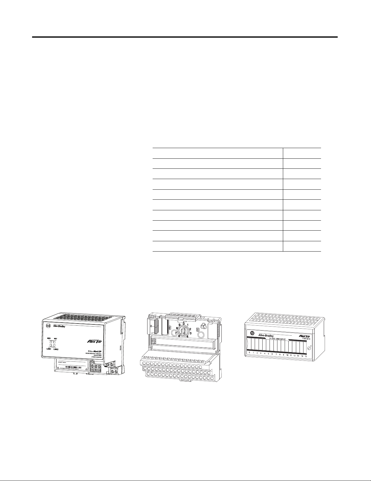
The FLEX I/O System
The FLEX I/O system is a small, modular I/O system for distributed
applications that performs all of the functions of rack-based I/O. The FLEX I/O
system contains the following components:
• Adapter – transfers read and write configuration data to and from the
I/O module
• Terminal base – contains a terminal strip to terminate wiring for two- or
three-wire devices
• I/O module – contains the bus interface and circuitry needed to perform
specific functions related to your application
Topic Page
The FLEX I/O System 1
Adapter Features 2
Types of Adapters 2
Hardware and Software Compatibility 2
What the Adapter Does 3
Use of the Control and Information Protocol (CIP) 3
Understanding the Producer/Consumer Model 3
Specifying the Requested Packet Interval (RPI) 4
Support of Rack Optimized and Direct Connections 4
Adapter I/O moduleTerminal base
1113
1112
45821

Publication 1794-UM066A-EN-P - February 2012
2 Overview of FLEX I/O and Your Redundant EtherNet/IP Adapter Module
The FLEX system consists of an adapter module, terminal base unit, DIN rail,
power supply, and adapter cabling components. You can use up to 8 terminal
bases per adapter module.
For detailed instructions on how to set up and install your module, refer to the
topic, Install Your FLEX I/O Adapter on page 7.
Adapter Features
The 1794-AENTR and 1794-AENTRXT adapter features include:
• use of EtherNet/IP messages encapsulated within standard TCP/UDP/IP
protocol
• common application layer with ControlNet and DeviceNet
• interfacing via Category 5 rated twisted pair cable
• half/full duplex 10 Mbit or 100 Mbit operation
• DIN rail mounting
• communication to and from other FLEX I/O modules on the same
DIN rail
• communication supported by RSLinx software
• IP address assigned via standard BootP/DHCP tools
• I/O configuration via RSLogix 5000 software
• no network scheduling required
• no routing tables required
Types of Adapters
The adapter refers to the following catalogs.
Hardware and Software
Compatibility
The adapters and the applications described in this manual are compatible with
the following firmware versions and software releases. Contact Rockwell
Automation if you need software or firmware upgrades to use this equipment.
Catalog Voltage Module
Capacity
Description
1794-AENTR 24V DC 8, max. Dual port EtherNet/IP adapter
1794-AENTRXT 24V DC 8, max. Dual port EtherNet/IP adapter with extended
temperatures range
Hardware and Software Compatibility
Product Firmware Version/
Software Release
1794-AENTR/1794-AENTRXT adapter 1.xx or higher
Logix 557x Controller 20 or higher
RSLogix 5000 Software 20 or higher
RSLinx software 2.59 or higher
Publication 1794-UM066A-EN-P - February 2012
Overview of FLEX I/O and Your Redundant EtherNet/IP Adapter Module 3
What the Adapter Does
The 1794-AENTR and 1794-AENTRXT adapters perform two primary tasks:
• Control of real time I/O data (implicit messaging). The adapter serves as a
bridge between I/O modules and the network.
• Support of messaging data for configuration and programming
information(explicit messaging).
Use of the Control and
Information Protocol (CIP)
The 1794-AENTR and 1794-AENTRXT adapters use the Control and
Information Protocol (CIP). CIP is the application layer protocol specified for
EtherNet/IP, the Ethernet Industrial Protocol, as well as for ControlNet and
DeviceNet. It is a message-based protocol that implements a relative path to send
a message from the producing device in a system to the consuming devices.
The producing device contains the path information that steers the message
along the proper route to reach its consumers. Since the producing device holds
this information, other devices along the path simply pass this information; they
do not need to store it.
This has two significant benefits:
• You do not need to configure routing tables in the bridging modules,
which greatly simplifies maintenance and module replacement.
• You maintain full control over the route taken by each message, which
enables you to select alternative paths for the same end device.
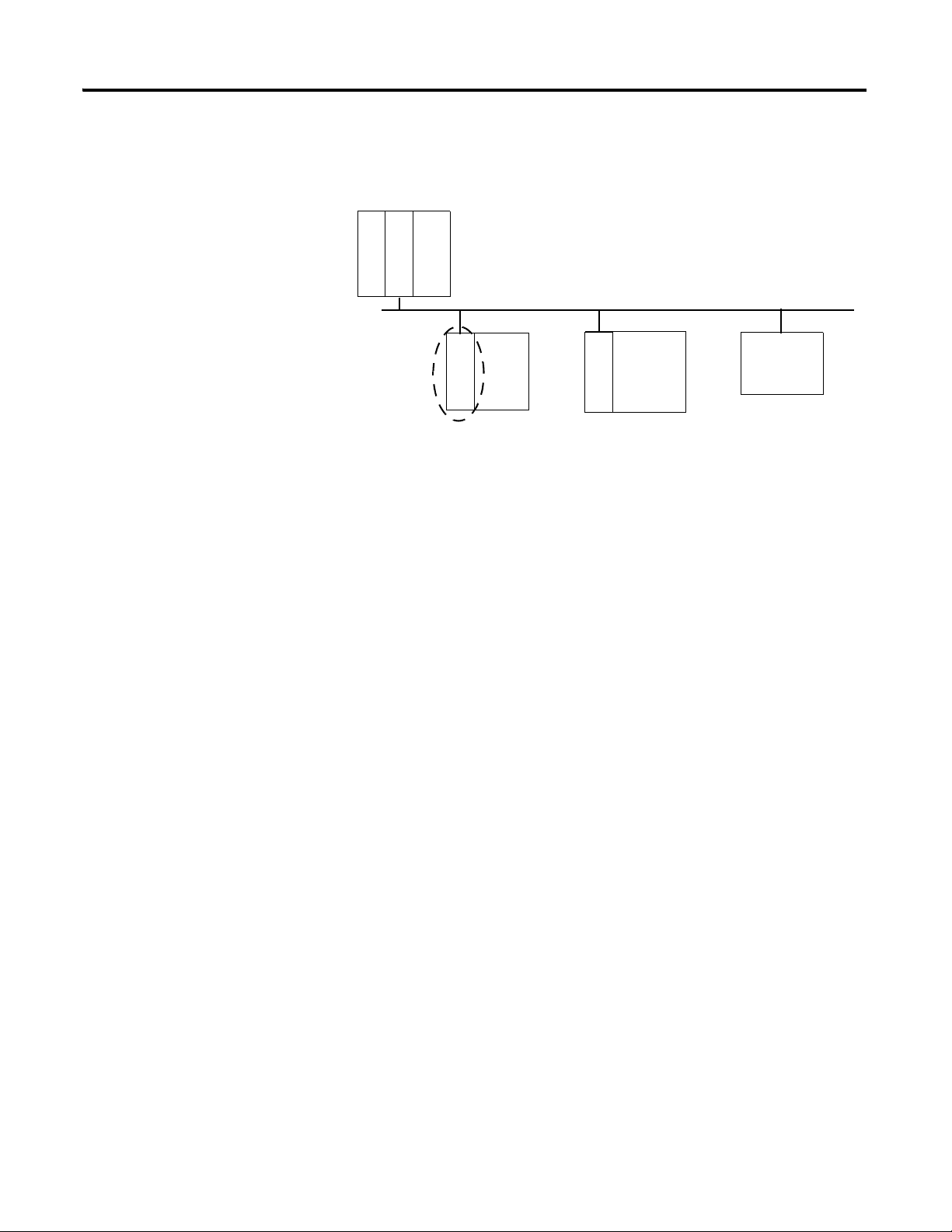
Understanding the
Producer/Consumer Model
The CIP producer/consumer networking model replaces the old
source/destination (master/slave) model. The producer/consumer model
reduces network traffic and increases speed of transmission. In traditional I/O
systems, controllers poll input modules to obtain their input status. In the CIP
system input modules are not polled by a controller. Instead, they produce
(multicast) their data either upon a change of state (COS) or periodically. The
frequency of update depends upon the options chosen during configuration and
where on the network the input module resides. The input module, therefore, is a
producer of input data and the controller is a consumer of the data.
L
5
5
7
2
EtherNet/IP network
E
N
2
T
R
Other
network
devices
A
E
N
T
R
FLEX
I/O
E
N
2
T
R
ControlLogix
I/O

Publication 1794-UM066A-EN-P - February 2012
4 Overview of FLEX I/O and Your Redundant EtherNet/IP Adapter Module
The controller can also produce data for other controllers to consume. The
produced and consumed data is accessible by multiple controllers over the
EtherNet/IP network. This data exchange conforms to the producer/consumer
model.
Specifying the Requested
Packet Interval (RPI)
The RPI is the update rate specified for a particular piece of data on the network.
The RPI can be specified for the adapter and include all of the I/O modules
communicating through it (using a rack optimized connection) or specified for a
particular module (using direct connection). When you add a module or an
adapter to the I/O configuration of a controller, you must enter the RPI as a
parameter. This value specifies how often to produce the data for that device. For
example, if you specify an RPI of 50 ms, it means that every 50ms the device
should send its data to the controller or the controller should send its data to the
device.
RPIs are only used for devices that produce data. For example, a ControlLogix
EtherNet/IP bridge module in the same chassis as the controller does not require
an RPI because it is not a data-producing member of the system; it is used only as
a bridge to remote racks.
Support of Rack Optimized
and Direct Connections
The 1794-AENTR and 1794-AENTRXT adapters support both direct and rack
optimized connections. A direct connection is a real-time data transfer link
between the controller and the device that the configuration data references.
Direct connection messaging occurs at a cyclic rate specified by the RPI during
configuration. A rack optimized connection is a grouping of data from more than
one I/O module into a single block of data sent over a single connection at the
same data rate.
Rack optimized connections reduce the total number of connections needed to
transfer data when using many I/O modules in a system. The following example
illustrates the benefit of rack optimized connections.
Assume you have set up a system that contains 8 discrete I/O modules interfaced
to an adapter. If you use direct connections to transfer data to each of the these
I/O modules, you need 8 connections to transfer all of the data, one to each of

Publication 1794-UM066A-EN-P - February 2012
Overview of FLEX I/O and Your Redundant EtherNet/IP Adapter Module 5
the 8 I/O modules. If you use a rack-optimized connection to transfer the data,
you only need a single connection – the connection to the adapter.
Refer to the EtherNet/IP Embedded Switch Technology Application Guide,
publication number ENET-AP005
, for more information on connections.
Mixing Rack Optimized and Direct Connections
You can mix communication formats for different I/O modules communicating
through the same adapter. I/O modules set up to use rack optimization will
communicate at the rate of the requested packet interval (RPI) configured for the
1794-AENTR or 1794-AENTRXT adapter. I/O modules configured for direct
communication will communicate at their own set RPIs and ignore the
adapter RPI.
Chapter Summary
This chapter briefly described the FLEX I/O system, the FLEX I/O dual port
EtherNet/IP adapters, and the basic adapter features. Read the next chapter to
learn how to physically install the adapters and connect them to the EtherNet/IP
network.
IMPORTANT
Although rack optimized connections offer an efficient way to use
resources, there are a few limitations on their use:
• You can only use rack optimized connections to send data to and
from discrete I/O modules. Analog I/O requires direct
connections.
• Rack optimized connections can contain I/O data and status
information only. Additional module information, such as
diagnostics, is not available through a rack-optimized connection.
• All data is sent at the same time at the RPI rate of the adapter.

Publication 1794-UM066A-EN-P - February 2012
6 Overview of FLEX I/O and Your Redundant EtherNet/IP Adapter Module
Notes:
Chapter
2
Install Your FLEX I/O Adapter
Overview
This chapter describes how to physically install the 1794-AENTR or
1794-AENTRXT adapter on the DIN rail and connect it to the EtherNet/IP
network. The following table lists where to find specific information.
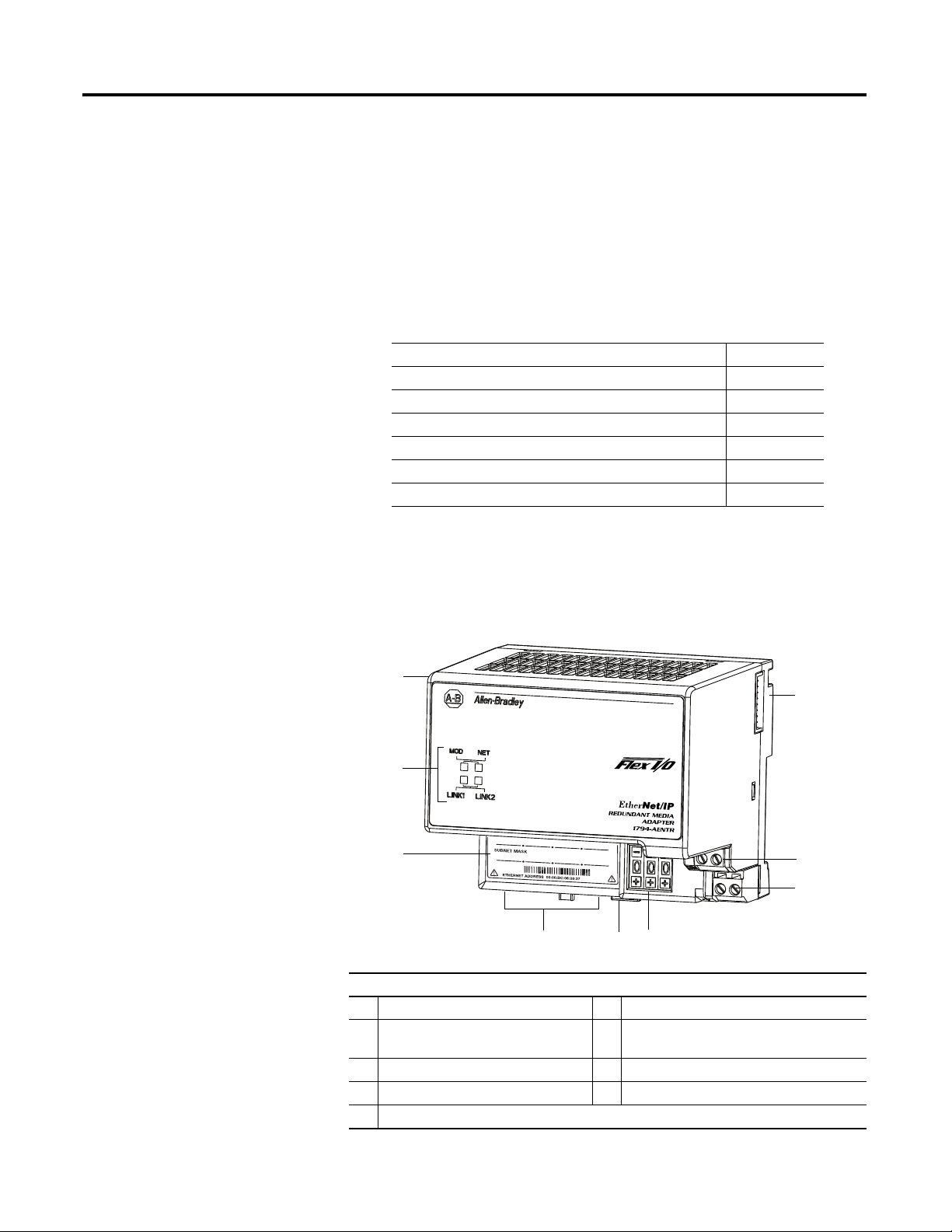
Module Components
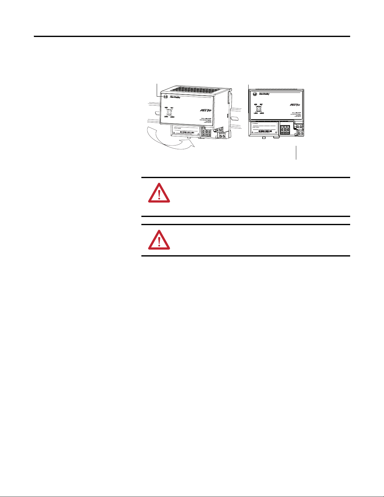
Use the following illustration to identify the external features of the FLEX I/O
EtherNet/IP adapter.
Dual Port EtherNet/IP Adapter – 1794-AENTR, 1794-AENTRXT
Topic Page
Module Components 7
Mount Your Adapter on a DIN Rail 8
Mount on a Panel or Wall 9
Connect Wiring 11
Set the Network Address 12
Mounting Dimensions 13
Component Identification
1 Dual Port EtherNet/IP adapter 6 Module locking tab
2 FlexBus connector 7 Network cable RJ45 connectors
(underside)
3 24V common connections 8 MAC ID label
4 24V DC connections 9 Status indicators
5 IP address switches
1
9
8
7
5
6
3
2
45821
4
Publication 1794-UM066A-EN-P - February 2012
8 Install Your FLEX I/O Adapter
Mount Your Adapter on a
DIN Rail
Follow these steps to mount the adapter on a new system before installing any
I/O modules.
1. Position the adapter module (A) on an IEC standard (35 x 7.5 x 1 mm)
top-hat DIN rail (B) at a slight angle (DIN rail: Allen-Bradley part
number 199-DR1; 46277-3; EN50022).
2. Hook the lip on the rear of the adapter onto the top of the DIN rail, and
pivot the adapter module onto the rail.
3. Press the adapter module down onto the DIN rail until flush. Locking tab
(C) snaps the adapter into position and locks it onto the DIN rail.
4. If the adapter module does not lock in place, use a screwdriver or similar
device to move the locking tab down while pressing the adapter module
flush onto the DIN rail, and release the locking tab to lock the adapter
module in place.
If necessary, push up on the locking tab to lock.
5. Connect the adapter wiring as shown in the Connect Wiring diagram.
ATTENTION: During mounting of all devices, be sure that all
debris (for example, metal chips, wire strands) is kept from falling
into the module. Debris that falls into the module could cause
damage on power up.
ATTENTION: Do not remove or replace an Adapter Module while
power is applied. Interruption of the backplane can result in
unintentional operation or machine motion.
45822
A B
C
Publication 1794-UM066A-EN-P - February 2012
Install Your FLEX I/O Adapter 9
Mount on a Panel or Wall
If mounting this adapter to a panel or wall, refer to publication 1794-TD013,
Panel Mounting Kit, Cat. No. 1794-NM1.
Mount or Replace the Adapter on an Existing System
1. Disconnect any wiring jumpered to the adjacent terminal base.
2. Remove the Ethernet connectors from the bottom of the adapter.
3. Disconnect any user power wiring connections to the adapter.
4. Open the module latching mechanism and remove the module from the
base unit to which the adapter will be attached.
5. Push the FlexBus connector toward the right side of the terminal base to
unplug the backplane connection.
6. Release the locking tab and remove the adapter module.
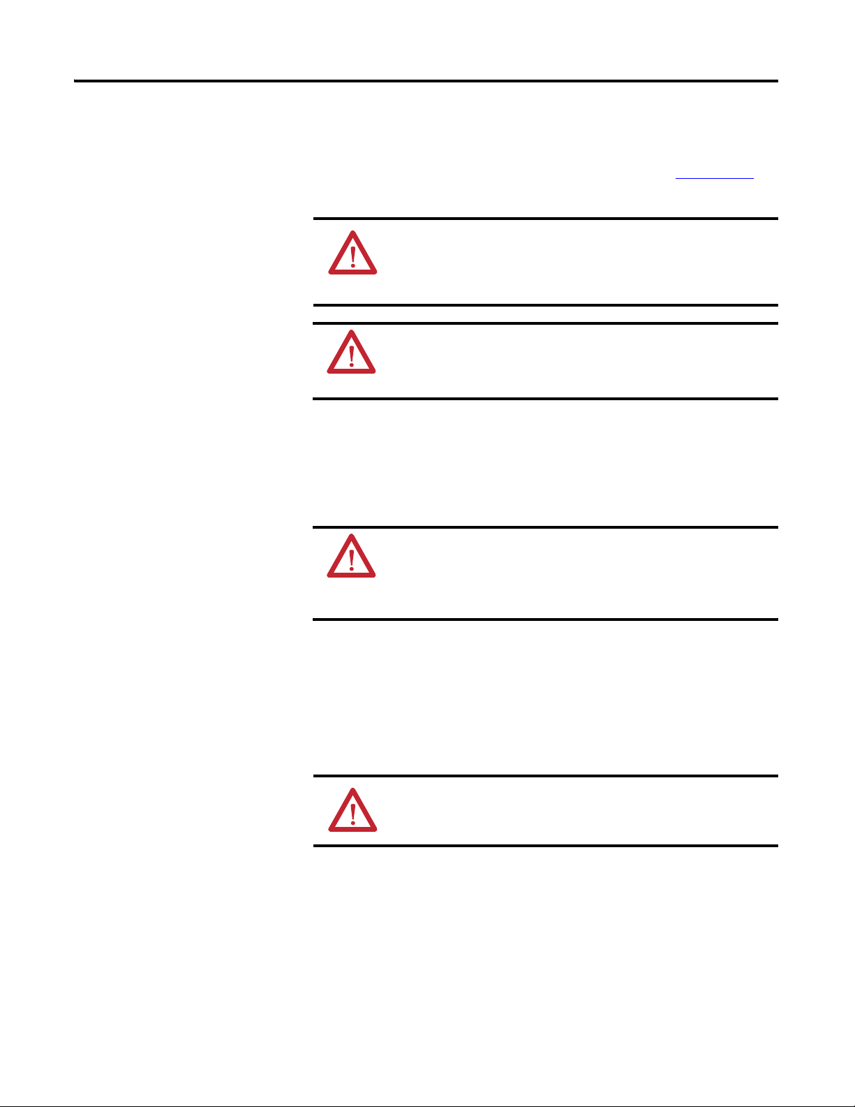
Before installing the new adapter, notice the notch on the right rear of the
adapter. This notch accepts the hook on the terminal base unit. The notch
is open at the bottom. The hook and adjacent connection point keep the
ATTENTION: If you insert or remove the module while backplane
power is on, an electrical arc can occur. This could cause an
explosion in hazardous location installations. Be sure that power is
removed or the area is nonhazardous before proceeding.
WARNING: When used in a Class I, Division 2, hazardous
location, this equipment must be mounted in a suitable enclosure
with proper wiring method that complies with the governing
electrical codes.
WARNING: If you connect or disconnect the communication cable
with power applied to the adapter or any device on the network, an
electrical arc can occur. This could cause an explosion in hazardous
location installations. Be sure that power is removed or the area is
nonhazardous before proceeding.
ATTENTION: Make certain the FlexBus connector is completely
clear of the adapter. The slide must be completely to the right and
the raised spot on the slide visible.
Publication 1794-UM066A-EN-P - February 2012
10 Install Your FLEX I/O Adapter
terminal base and the adapter tight together, reducing the possibility of a
break in communication over the backplane.
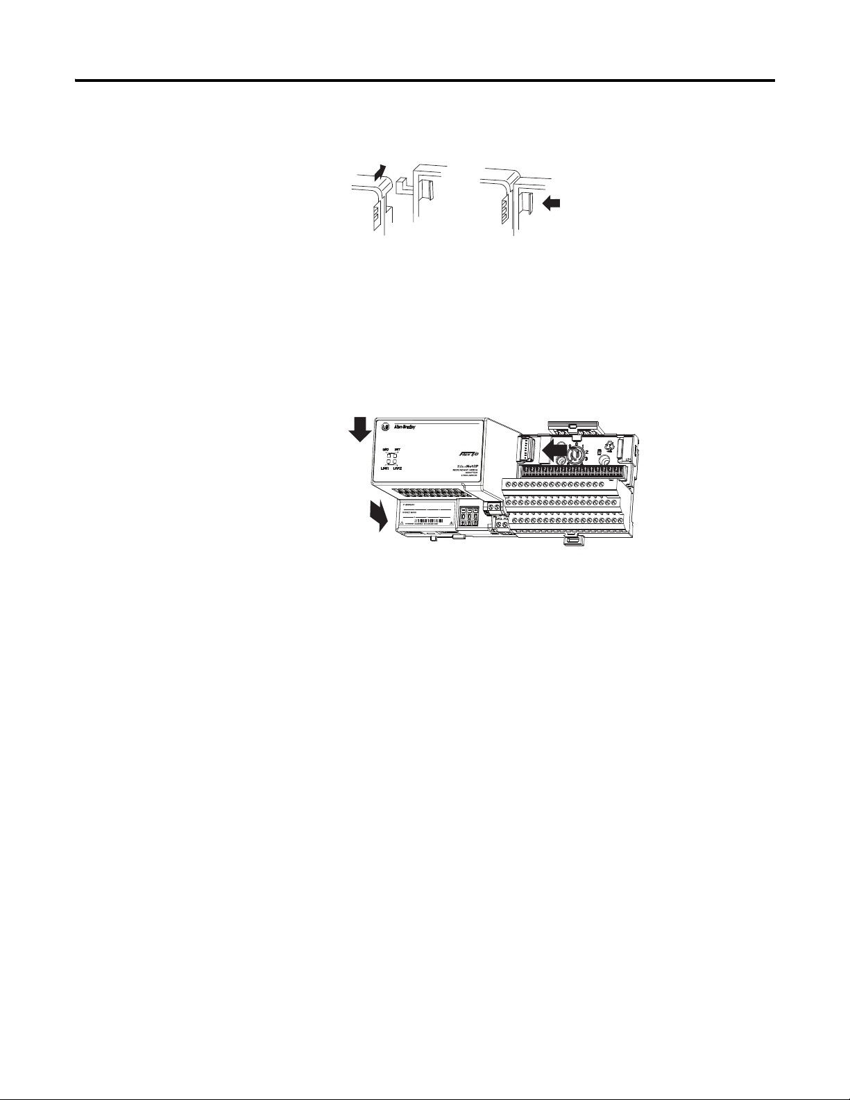
7. Complete the adapter mounting as shown below.
Push down and in at the same time to lock the adapter to the DIN rail.
If the adapter does not lock in place, use a screwdriver or similar device to
move the locking tab down while pressing the adapter flush onto the DIN
rail, and release the locking tab to lock the adapter module in place. If
necessary, push up on the locking tab to lock.
When the adapter is locked onto the DIN rail, gently push the FlexBus
connector into the adapter to complete the backplane.
8. Reinstall the module in the adjacent terminal base unit.
Publication 1794-UM066A-EN-P - February 2012
Install Your FLEX I/O Adapter 11
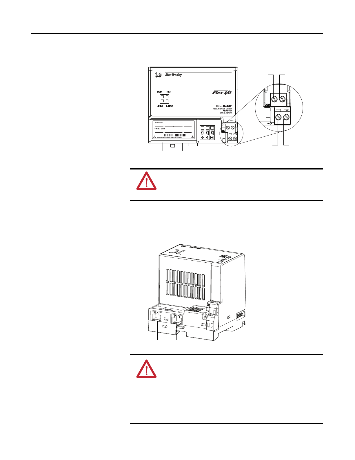
Connect Wiring
1. Connect an Ethernet network cable to the RJ45 connector (A).
2. Connect the redundant Ethernet network cable to the RJ45
connector (B).
WARNING: If you connect or disconnect wiring while the
field-side power is on, an electrical arc can occur. This could cause
an explosion in hazardous location installations. Be sure that
power is removed or the area is nonhazardous before proceeding.
ATTENTION: When connecting wiring, torque terminal screws C,
D, E and F to 0.8 Nm (7 lb-in.).
ATTENTION: If multiple power sources are used, do not exceed
the specified isolation voltage.
ATTENTION: Power wiring must be less than 10 m (32.8 ft.) in
length.
ATTENTION: Do not wire more than two conductors on any single
terminal.
A
FE
CD
45823
B
A B
Publication 1794-UM066A-EN-P - February 2012
12 Install Your FLEX I/O Adapter
3. Connect 24V DC common to the left side of the upper connector,
terminal F.
4. Connect +24V DC input power to the left side of the lower
connector, terminal C.
5. Use connections D and E to pass +24V DC common (E) and
24V DC power (D) to the next module in the series (if required).
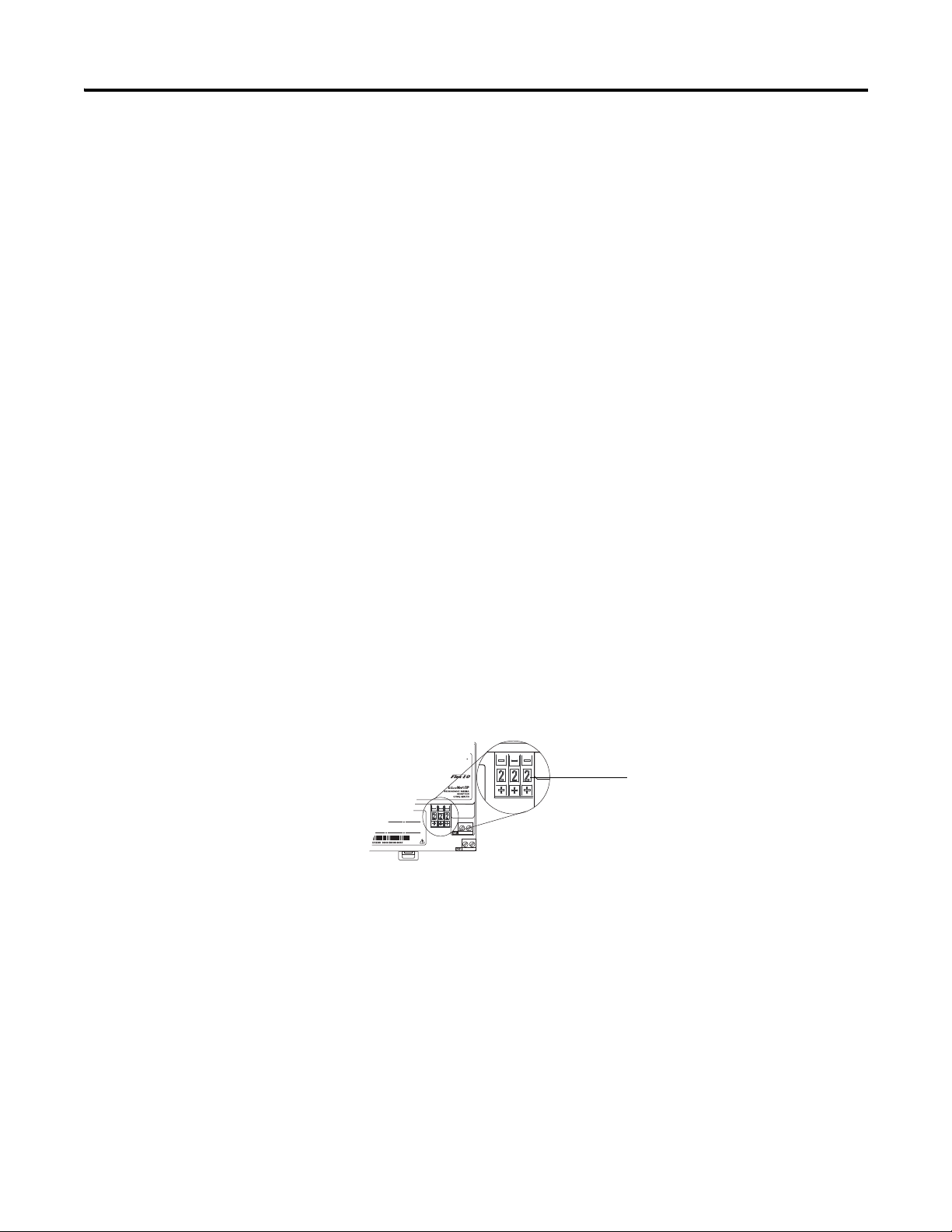
Set the Network Address
The adapter ships with the thumbwheel switches set to 999 and DHCP enabled.
You can set the network Internet Protocol (IP) address in these ways:
• Use the thumbwheel switches on the module.
• Use a Dynamic Host Configuration Protocol (DHCP) server, such as
Rockwell Automation DHCP.
• Retrieve the IP address (if previously set) from nonvolatile memory.
The adapter reads the thumbwheel switches first to determine if the switches are
set to a valid number. You set the node address by using the three-position
thumbwheel switch. Press the + or - buttons to change the number. Valid settings
are 001…254.
When the switches are set to a valid number, the adapter IP address is
192.168.1.xxx (where xxx represents the number set on the switches). The
adapter subnet mask is 255.255.255.0 and the gateway address is set to 0.0.0.0.
The adapter does not have a host name assigned, or use any Domain Name
System when using the thumbwheel settings.
If you set the switches to an invalid number (such as 000, or a value greater than
254), the adapter checks to see if you enabled DHCP.
45824
Press the + or - buttons to
change the numbers
Publication 1794-UM066A-EN-P - February 2012
Install Your FLEX I/O Adapter 13
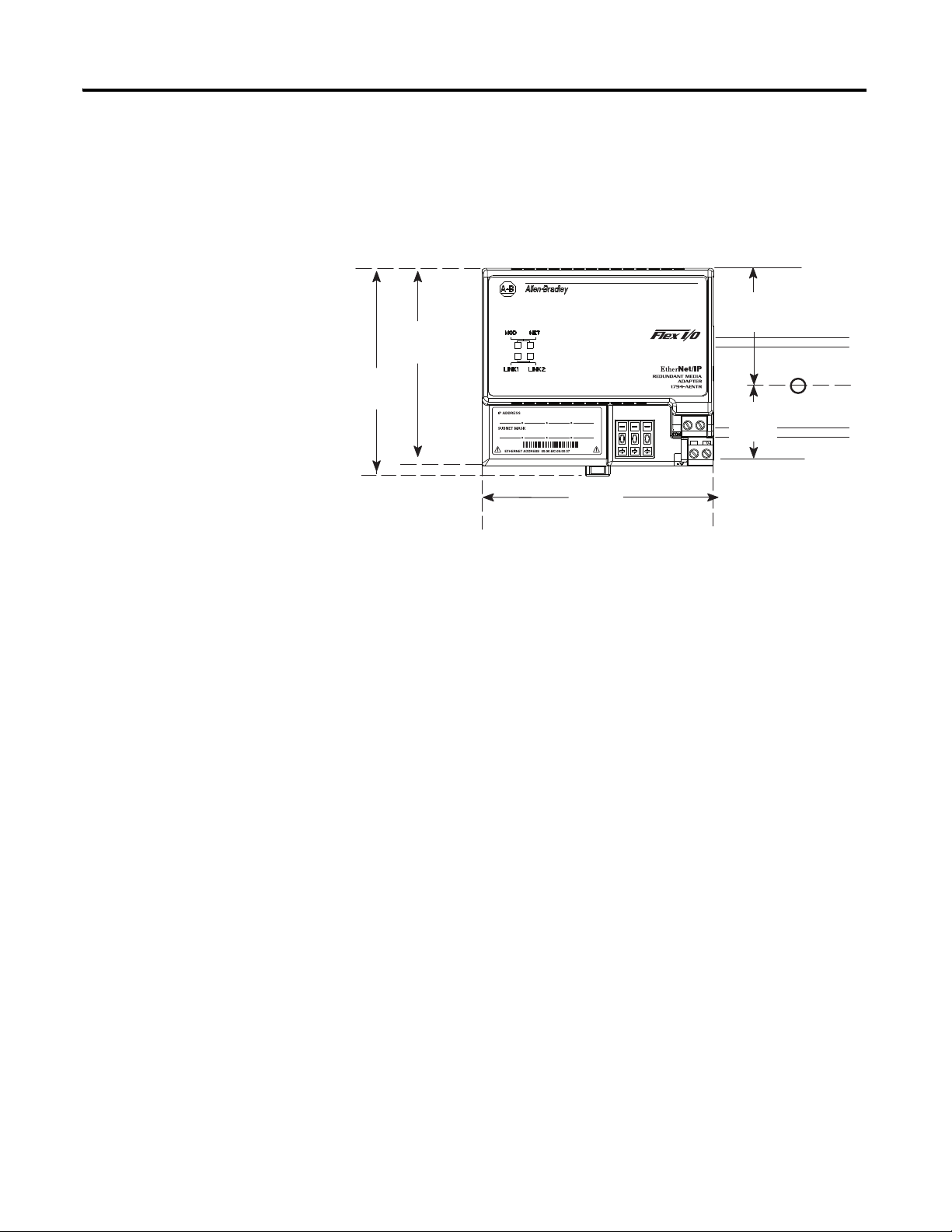
Mounting Dimensions
The module has the following mounting dimensions.
45826
1794-AENTR shown
Millimeters
(Inches)
80.4
(3.16)
87.4
(3.44)
94
(3.70)
1794-AENTR, 1794-AENTRXT
87.4 H x 94W x 92D
(344H x 3.7W x 3.6D)
50
(1.96)
30.4
(1.19)

Publication 1794-UM066A-EN-P - February 2012
14 Install Your FLEX I/O Adapter
Notes:

15 Publication 1794-UM066A-EN-P - February 2012
Chapter
3
Configure the Adapter for Your
EtherNet/IP Network
Overview
This chapter describes how to configure the 1794-AENTR or 1794-AENTRXT
adapter module for the ControlLogix system.
Configuration
Requirements
Before you can use your 1794-AENTR or 1794-AENTRXT adapter, you must
configure its IP address, and optionally, its subnet mask and gateway address. You
can use the Rockwell BootP/DHCP utility to perform the configuration. You
can also use generic BootP software or, within some limitations, a DHCP server.
IP Address
The IP address identifies each node on the IP network (or system of connected
networks). Each TCP/IP node on a network (including the 1794-AENTR or
1794-AENTRXT adapter) must have a unique IP address.
Topic Page
Configuration Requirements
15
IP Address
15
Gateway Address
16
Subnet Mask
17
Use the Rockwell BootP/DHCP Utility
18
Configure Your Adapter using DHCP Software
21
IMPORTANT
When using the BootP protocol, you must enter the Ethernet
hardware address of your adapter. Rockwell assigns each
1794-AENTR or 1794-AENTRXT adapter a unique 48-bit hardware
address at the factory. The address is printed on a label on the front
of your 1794-AENTR or 1794-AENTRXT adapter. It consists of six
hexadecimal digits separated by colons. This address is fixed by the
hardware and cannot be changed.
If you change or replace the 1794-AENTR or 1794-AENTRXT adapter,
you must enter the new Ethernet hardware address of the adapter
when you configure the new adapter.

Publication 1794-UM066A-EN-P - February 2012
16 Configure the Adapter for Your EtherNet/IP Network
The IP address is 32 bits long and has a Net ID part and a Host ID part.
Networks are classified A, B, C, (or other). The class of the network determines
how an IP address is formatted.
You can distinguish the class of the IP address from the first integer in its
dotted-decimal IP address as follows:
Each node on the same physical network must have an IP address of the same
class and must have the same Net ID. Each node on the same network must have
a different Host ID thus giving it a unique IP address.
IP addresses are written as four decimal integers (0-255) separated by periods
where each integer gives the value of one byte of the IP address.
Gateway Address
The Gateway Address is the default address of a network. It provides a single
domain name and point of entry to the site. Gateways connect individual physical
networks into a system of networks. When a node needs to communicate with a
node on another network, a gateway transfers the data between the two
Class A
Class B
Class C
Net ID
Net ID
Net ID
Host ID
Host ID
Host ID
0
0
0
1 0
1 1 0
8
9
16
24
17
31
31
31
25
0
Range of first integer Class Range of first integer Class
0…127 A 192…223 C
128…191 B 224…255 other
EXAMPLE
For example, the 32-bit IP address:
10000000 00000001 00000000 00000001 is written as
128.1.0.1.
TIP
Contact your network administrator or the Network Information
Center for a unique fixed IP address to assign to your module.
Publication 1794-UM066A-EN-P - February 2012
Configure the Adapter for Your EtherNet/IP Network 17
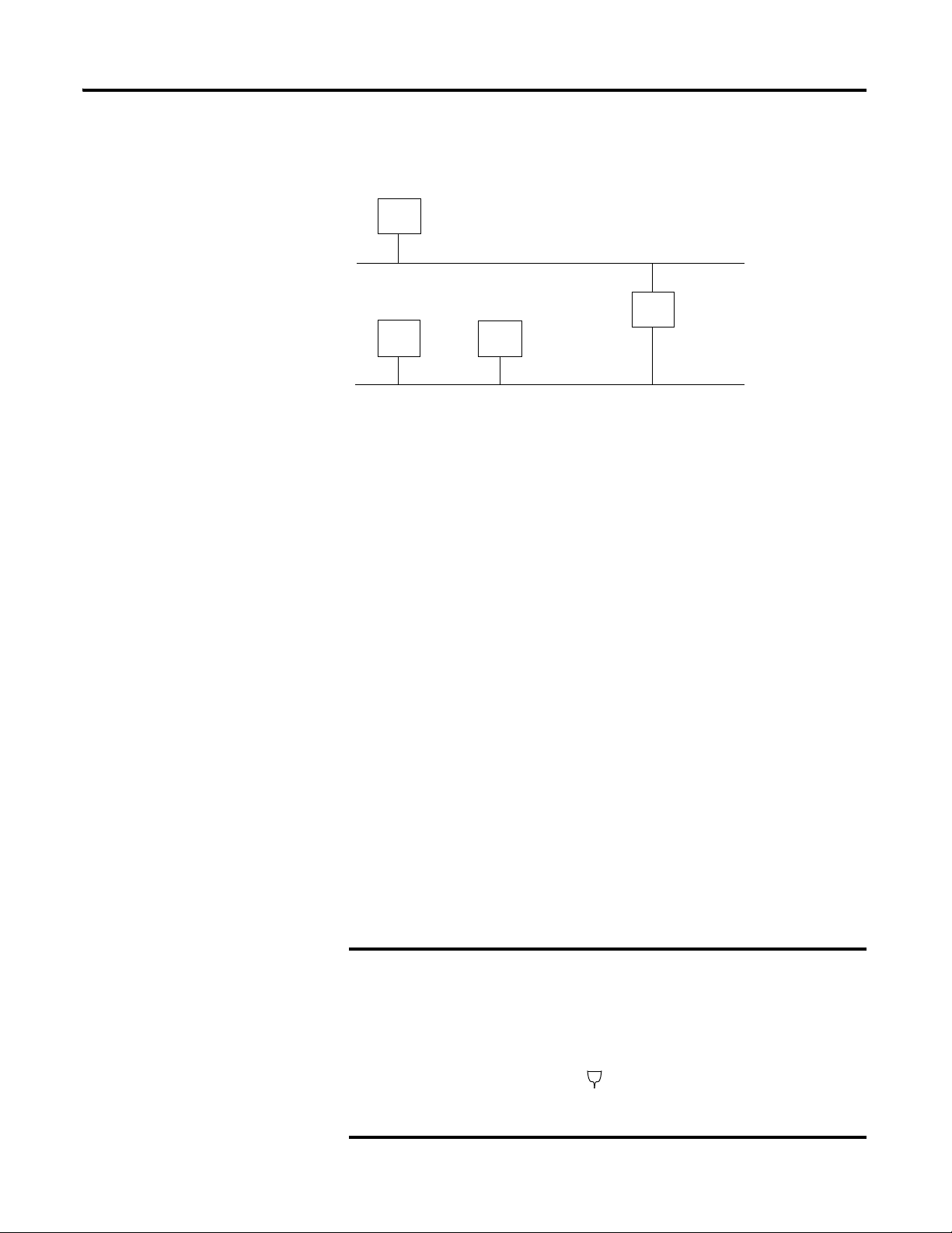
networks. The following figure shows gateway G connecting Network 1 with
Network 2.
When host B with IP address 128.2.0.1 communicates with host C, it knows
from C’s IP address that C is on the same network. In an Ethernet environment,
B then resolves C’s IP address into a hardware address (MAC address) and
communicates with C directly.
When host B communicates with host A, it knows from A’s IP address that A is
on another network (the net IDs are different). In order to send data to A, B must
have the IP address of the gateway connecting the two networks. In this example,
the gateway’s IP address on Network 2 is 128.2.0.3.
The gateway has two IP addresses (128.1.0.2 and 128.2.0.3). The first must be
used by hosts on Network 1 and the second must be used by hosts on Network 2.
To be usable, a host’s gateway must be addressed using a net ID matching its own.
Subnet Mask
The subnet mask is used for splitting IP networks into a series of subgroups, or
subnets. The mask is a binary pattern that is matched up with the IP address to
turn part of the Host ID address field into a field for subnets.
Take Network 2 (a Class B network) in the previous example and add another
network. Selecting the following subnet mask would add two additional net ID
bits, allowing for four logical networks:
EXAMPLE
Take Network 2 (a Class B network) in the previous example
and add another network. Selecting the following subnet mask
would add two additional net ID bits, allowing for four logical
networks:
Network 1
Network 2
128.2.0.3
128.1.0.2
128.1.0.1
128.2.0.1
128.2.0.2
A
B
C
G
11111111 11111111 11000000 00000001 = 255.255.192.0
These two bits of the host ID used to
extend the net ID

Publication 1794-UM066A-EN-P - February 2012
18 Configure the Adapter for Your EtherNet/IP Network
Two bits of the Class B host ID have been used to extend the net ID. Each unique
combination of bits in the part of the Host ID where subnet mask bits are 1
specifies a different logical network.
The new configuration is:
A second network with Hosts D and E was added. Gateway G2 connects
Network 2.1 with Network 2.2.
Hosts D and E use Gateway G2 to communicate with hosts not on Network 2.2.
Hosts B and C use Gateway G to communicate with hosts not on Network 2.1.
When B is communicating with D, G (the configured gateway for B) routes the
data from B to D through G2.
Use the Rockwell
BootP/DHCP Utility
The Rockwell BootP/DHCP utility is a stand alone program that incorporates
the functionality of standard BootP/DHCP software with a user-friendly
graphical interface. It is located in the Utils directory on the RSLogix 5000
installation CD. The module must have DHCP enabled (factory default and the
network address switches set to an illegal value) to use the utility.
To configure your module using the BootP/DHCP utility, perform the following
steps:
1. Run the BootP/DHCP software.
128.2.64.1
Network 1
Network 2.1
Network 2.2
128.1.0.1
128.1.0.2
128.2.128.3
A
B
C
G
D
128.2.128.1
128.2.128.2
E
G2
128.2.64.3
Publication 1794-UM066A-EN-P - February 2012
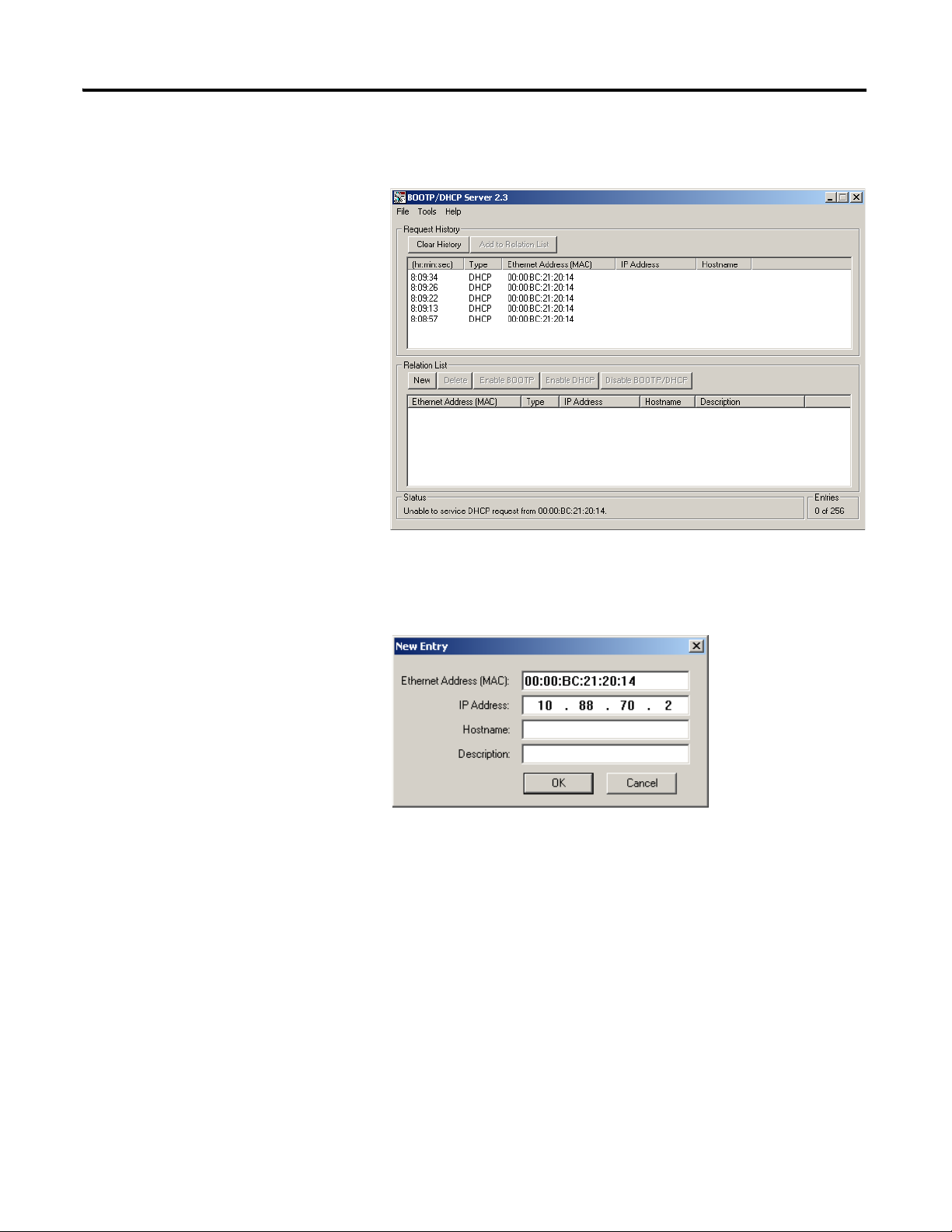
Configure the Adapter for Your EtherNet/IP Network 19
The BOOTP/DHCP Request History dialog appears showing the
hardware addresses of devices issuing BootP/DHCP requests.
2. Double-click the hardware address of the device you want to configure.
The New Entry dialog appears showing the device’s Ethernet
Address (MAC).
3. Enter the IP Address you want to assign to the device and click OK.
Loading...