


 Loading...
Installation Instructions
ControlNet-to-DeviceNet Linking Device
Catalog Number 1788-CN2DN
Topic |
Page |
|
|
Important User Information |
2 |
|
|
About the CN2DN Linking Device |
7 |
|
|
Parts List |
8 |
|
|
Required System Components |
9 |
|
|
Install the CN2DN Device |
9 |
|
|
Mount the CN2DN Device on a DIN Rail |
10 |
|
|
Mount the CN2DN Device on a Panel or Other Fixture |
12 |
|
|
Wire a Power Supply to the CN2DN Device |
13 |
|
|
Set the Node Addresses and Communication Rate |
15 |
|
|
Connect the CN2DN Device to a ControlNet Network |
16 |
|
|
Connect the CN2DN Device to a DeviceNet Network |
17 |
|
|
Uninstall the CN2DN Linking Device |
19 |
|
|
Interpret the LED Indicators |
21 |
|
|
Troubleshoot the DeviceNet Network |
29 |
|
|
Troubleshoot the ControlNet Network |
46 |
|
|
Specifications |
47 |
|
|
Additional Resources |
51 |
|
|
Publication 1788-IN052D-EN-P - February 2007
2 ControlNet-to-DeviceNet Linking Device
Important User Information
Solid state equipment has operational characteristics differing from those of electromechanical equipment. Safety Guidelines for the Application, Installation and Maintenance of Solid State Controls (publication SGI-1.1 available from your local Rockwell Automation sales office or online at http://literature.rockwellautomation.com) describes some important differences between solid state equipment and hard-wired electromechanical devices. Because of this difference, and also because of the wide variety of uses for solid state equipment, all persons responsible for applying this equipment must satisfy themselves that each intended application of this equipment is acceptable.
In no event will Rockwell Automation, Inc. be responsible or liable for indirect or consequential damages resulting from the use or application of this equipment.
The examples and diagrams in this manual are included solely for illustrative purposes. Because of the many variables and requirements associated with any particular installation, Rockwell Automation, Inc. cannot assume responsibility or liability for actual use based on the examples and diagrams.
No patent liability is assumed by Rockwell Automation, Inc. with respect to use of information, circuits, equipment, or software described in this manual.
Reproduction of the contents of this manual, in whole or in part, without written permission of Rockwell Automation, Inc., is prohibited.
Throughout this manual, when necessary, we use notes to make you aware of safety considerations.
|
WARNING |
|
Identifies information about practices or circumstances that can cause an explosion in |
||
|
|
|
|
|
|
|
|
|
|
|
a hazardous environment, which may lead to personal injury or death, property |
|
|
|
|
|
damage, or economic loss. |
|
|
|
|
|
|
|
|
|
|
|
|
|
|
|
|
|
Identifies information that is critical for successful application and understanding of |
|
IMPORTANT |
|
|||
|
|
the product. |
|||
|
|
|
|
|
|
|
|
|
|
|
|
|
|
|
|
|
|
|
ATTENTION |
|
Identifies information about practices or circumstances that can lead to personal |
||
|
|
|
|
|
|
|
|
|
|
|
injury or death, property damage, or economic loss. Attentions help you to identify a |
|
|
|
|
|
hazard, avoid a hazard and recognize the consequences. |
|
|
|
|
|
|
SHOCK HAZARD
Labels may be located on or inside the equipment, for example, a drive or motor, to alert people that dangerous voltage may be present.
BURN HAZARD
Labels may be located on or inside the equipment, for example, a drive or motor, to alert people that surfaces may be at dangerous temperatures.
Publication 1788-IN052D-EN-P - February 2007
ControlNet-to-DeviceNet Linking Device 3
North American Hazardous Location Approval
The following Information applies when operating |
|
Informations sur l'utilisation de cet équipement en |
|
||||||||||
this equipment in hazardous locations: |
|
environnements dangereux: |
|
||||||||||
|
|
|
|
|
|
|
|
|
|
||||
Products marked "CL I, DIV 2, GP A, B, C, D" are |
|
Les produits marqués "CL I, DIV 2, GP A, B, C, D" |
|
||||||||||
suitable for use in Class I Division 2 Groups A, B, |
|
ne conviennent qu'à une utilisation en |
|
||||||||||
C, D, Hazardous Locations and nonhazardous |
|
environnements de Classe I Division 2 Groupes A, |
|
||||||||||
locations only. Each product is supplied with |
|
B, C, D dangereux et non dangereux. Chaque |
|
||||||||||
markings on the rating nameplate indicating the |
|
produit est livré avec des marquages sur sa plaque |
|
||||||||||
hazardous location temperature code. When |
|
d'identification qui indiquent le code de |
|
||||||||||
combining products within a system, the most |
|
température pour les environnements dangereux. |
|
||||||||||
adverse temperature code (lowest "T" number) |
|
Lorsque plusieurs produits sont combinés dans un |
|
||||||||||
may be used to help determine the overall |
|
système, le code de température le plus |
|
||||||||||
temperature code of the system. Combinations of |
|
défavorable (code de température le plus faible) |
|
||||||||||
equipment in your system are subject to |
|
peut être utilisé pour déterminer le code de |
|
||||||||||
investigation by the local Authority Having |
|
température global du système. Les combinaisons |
|
||||||||||
Jurisdiction at the time of installation. |
|
d'équipements dans le système sont sujettes à |
|
||||||||||
|
|
|
|
|
|
|
inspection par les autorités locales qualifiées au |
|
|||||
|
|
|
|
|
|
|
moment de l'installation. |
|
|||||
|
|
|
|
|
|
|
|
|
|
|
|
|
|
|
|
|
|
|
|
|
|
|
|
|
|
|
|
|
|
|
|
|
EXPLOSION HAZARD |
|
|
|
|
|
RISQUE D'EXPLOSION |
|
|
|
WARNING |
|
|
|
AVERTISSEMEN |
|
|
||||||
|
|
|
|
|
|
|
|
|
|
|
|||
|
|
|
|
|
Do not disconnect equipment |
|
|
|
|
|
|
Couper le courant ou s'assurer |
|
|
|
|
|
|
unless power has been removed |
|
|
|
|
|
|
que l'environnement est classé |
|
|
|
|
|
|
or the area is known to be |
|
|
|
|
|
|
non dangereux avant de |
|
|
|
|
|
|
nonhazardous. |
|
|
|
|
|
|
débrancher l'équipement. |
|
|
|
|
|
|
Do not disconnect connections to |
|
|
|
|
|
|
Couper le courant ou s'assurer |
|
|
|
|
|
|
this equipment unless power has |
|
|
|
|
|
|
que l'environnement est classé |
|
|
|
|
|
|
been removed or the area is |
|
|
|
|
|
|
non dangereux avant de |
|
|
|
|
|
|
known to be nonhazardous. |
|
|
|
|
|
|
débrancher les connecteurs. Fixer |
|
|
|
|
|
|
Secure any external connections |
|
|
|
|
|
|
tous les connecteurs externes |
|
|
|
|
|
|
that mate to this equipment by |
|
|
|
|
|
|
reliés à cet équipement à l'aide |
|
|
|
|
|
|
using screws, sliding latches, |
|
|
|
|
|
|
de vis, loquets coulissants, |
|
|
|
|
|
|
threaded connectors, or other |
|
|
|
|
|
|
connecteurs filetés ou autres |
|
|
|
|
|
|
means provided with this product. |
|
|
|
|
|
|
moyens fournis avec ce produit. |
|
|
|
|
|
|
Substitution of components may |
|
|
|
|
|
|
La substitution de composants |
|
|
|
|
|
|
impair suitability for Class I, |
|
|
|
|
|
|
peut rendre cet équipement |
|
|
|
|
|
|
Division 2. |
|
|
|
|
|
|
inadapté à une utilisation en |
|
|
|
|
|
|
If this product contains batteries, |
|
|
|
|
|
|
environnement de Classe I, |
|
|
|
|
|
|
|
|
|
|
|
|
Division 2. |
|
|
|
|
|
|
|
they must only be changed in an |
|
|
|
|
|
|
|
|
|
|
|
|
|
area known to be nonhazardous. |
|
|
|
|
|
|
S'assurer que l'environnement est |
|
|
|
|
|
|
|
|
|
|
|
|
|
classé non dangereux avant de |
|
|
|
|
|
|
|
|
|
|
|
|
|
changer les piles. |
|
|
|
|
|
|
|
|
|
|
|
|
|
|
|
Publication 1788-IN052D-EN-P - February 2007

4 ControlNet-to-DeviceNet Linking Device
European Hazardous Location Approval
European Zone 2 Certification (The following applies when the product bears the EEx Marking)
This equipment is intended for use in potentially explosive atmospheres as defined by European Union Directive 94/9/EC.
The LCIE (Laboratoire Central des Industries Electriques) certifies that this equipment has been found to comply with the Essential Health and Safety Requirements relating to the design and construction of Category 3 equipment intended for use in potentially explosive atmospheres, given in Annex II to this Directive.
Compliance with the Essential Health and Safety Requirements has been assured by compliance with EN 60079-15.
IMPORTANT
This equipment is not resistant to sunlight or other sources of UV radiation.
Equipment of lesser Enclosure Type Rating must be installed in an enclosure providing at least IP54 protection when applied in Class I, Zone 2 environments.
This equipment shall be used within its specified ratings defined by Allen-Bradley.
Provision shall be made to prevent the rated voltage from being exceeded by transient disturbances of more than 40% when applied in Class I, Zone 2 environments.
Publication 1788-IN052D-EN-P - February 2007

|
|
|
ControlNet-to-DeviceNet Linking Device 5 |
|
|
|
|
Environment and Enclosure |
|||
|
|
|
|
|
|
|
This equipment is intended for use in a Pollution Degree 2 industrial |
ATTENTION |
|||
|
|
|
environment, in overvoltage Category II applications (as defined in IEC |
|
|
|
publication 60664-1), at altitudes up to 2000 m (1.24 mi) without |
|
|
|
derating. |
This equipment is considered Group 1, Class A industrial equipment according to IEC/CISPR Publication 11. Without appropriate precautions, there may be potential difficulties ensuring electromagnetic compatibility in other environments due to conducted as well as radiated disturbance.
This equipment is supplied as open-type equipment. It must be mounted within an enclosure that is suitably designed for those specific environmental conditions that will be present and appropriately designed to prevent personal injury resulting from accessibility to live parts. The enclosure must have suitable flame-retardant properties to prevent or minimize the spread of flame, complying with a flame spread rating of 5VA, V2, V1, V0 (or equivalent) if non-metallic. The interior of the enclosure must be accessible only by the use of a tool. Subsequent sections of this publication may contain additional information regarding specific enclosure type ratings that are required to comply with certain product safety certifications.
Besides this publication, see:
Industrial Automation Wiring and Grounding Guidelines, publication 1770-4.1.
NEMA Standards publication 250 and IEC publication 60529, as applicable, for explanations of the degrees of protection provided by different types of enclosure.
Publication 1788-IN052D-EN-P - February 2007
6 ControlNet-to-DeviceNet Linking Device
Prevent Electrostatic Discharge
ATTENTION This equipment is sensitive to electrostatic discharge, which can
cause internal damage and affect normal operation. Follow these guidelines when you handle this equipment:
•Touch a grounded object to discharge potential static.
•Wear an approved grounding wriststrap.
•Do not touch connectors or pins on component boards.
•Do not touch circuit components inside the equipment.
•Use a static-safe workstation, if available.
•Store the equipment in appropriate static-safe packaging when not in use.
Publication 1788-IN052D-EN-P - February 2007

ControlNet-to-DeviceNet Linking Device 7
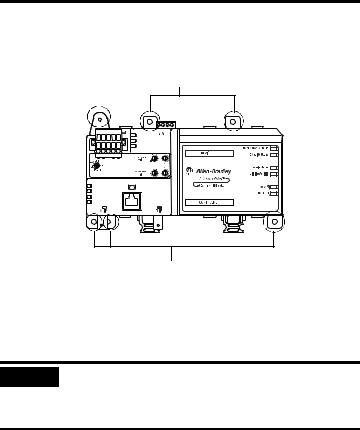
About the CN2DN Linking Device
Use following graphic to identify the components of your ControlNet-to-DeviceNet linking device.
CN2DN Linking Device Components
Power Port and |
DeviceNet Node Address |
|
Switches |
||
Connector |
||
|
||
DeviceNet Port and |
LED Indicators |
|
Connector |
|
|
DeviceNet Baud |
|
|
Rate Switch |
|
|
Network |
|
|
Access Port |
|
|
ControlNet Connection Ports |
ControlNet Node Address |
|
Switches |
||
|
The DeviceNet connection port is located on the top left corner of the device. See the section titled Connect the CN2DN Device to a DeviceNet Network for more information.
Rotary switches to set the ControlNet node address, DeviceNet node address, and the DeviceNet communication rate are located just below the power and DeviceNet ports. See the section titled Uninstall the CN2DN Linking Device for more information.
ATTENTION |
The Network Access Port (NAP) is intended for local temporary |
|
programming use only. It is not for permanent connection. |
Use only specified NAP cable to the network.
Located below the rotary switches, the ControlNet network access port allows for easy access of the ControlNet network using a laptop and 1784-PCC card. Use 1786-CP connection cable to access the ControlNet network using the NAP port.
Publication 1788-IN052D-EN-P - February 2007
8 ControlNet-to-DeviceNet Linking Device
Two ControlNet connection ports are located on the bottom left side of the device and provide the availability to connect a redundant network. See the section titled Connect the CN2DN Device to a ControlNet Network on page 16 for more information.
For more information about the power port and connector, see the section titled Wire a Power Supply to the CN2DN Device on page 13.
For more information about the LED indicators, see the section titled Interpret the LED Indicators on page 21.
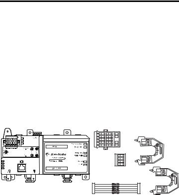
Parts List
The following parts are included with the 1788-CN2DN linking device.
1788-CN2DN Parts
DeviceNet
Connector
End Anchors
Power
Connector
121 Ω Resistors
1788-CN2DN
31670-M
•One 1788-CN2CN linking device
•One power input connector
•One DeviceNet 10-pin linear connector
•Five 121 Ω resistors
•Two end anchors
Publication 1788-IN052D-EN-P - February 2007

ControlNet-to-DeviceNet Linking Device 9
Required System Components
In order to install your 1788-CN2DN device, you will need the following system components.
•A 24V dc power supply and
•A securely installed zinc-plated, yellow-chrome steel, DIN rail, panel, or other suitable fixture.
Install the CN2DN Device
Complete the following tasks to install the CN2DN Linking Device.
•Mount the CN2DN Device on a DIN Rail
•Mount the CN2DN Device on a Panel or Other Fixture
•Wire a Power Supply to the CN2DN Device
•Uninstall the CN2DN Linking Device
•Set the Node Addresses and Communication Rate
•Connect the CN2DN Device to a ControlNet Network
•Connect the CN2DN Device to a DeviceNet Network
Publication 1788-IN052D-EN-P - February 2007
10 ControlNet-to-DeviceNet Linking Device
Mount the CN2DN Device on a DIN Rail
ATTENTION |
This product is grounded through the DIN rail to chassis ground. Use |
||
|
|
|
zinc plated yellow-chromate steel DIN rail to assure proper grounding. |
|
|
|
The use of other DIN rail materials (for example, aluminum and |
|
|
|
plastic) that can corrode, oxidize, or are poor conductors, can result in |
|
|
|
improper or intermittent grounding. Secure DIN rail to mounting |
|
|
|
surface approximately every 200 mm (7.87 in.) and use end-anchors |
|
|
|
appropriately. |
|
|
|
|
|
|
|
|
IMPORTANT
The DIN rail must be properly grounded. See publication Industrial Automation Wiring and Grounding Guidelines, publication 1770-4.1 for more information about DIN rail grounding.
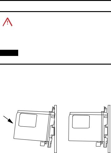
Complete the following steps to mount the CN2DN device on a DIN rail.
1.Align the CN2DN device over the DIN rail.
2.Press the CN2DN device onto the DIN rail until the DIN rail latches lock the linking device in place.
Press Forward
and Down
Publication 1788-IN052D-EN-P - February 2007
ControlNet-to-DeviceNet Linking Device 11
3.Clip each of the end anchors onto the DIN rail next to the CN2DN device.
End Anchor onto DIN Rail
DIN Rail
 Clip On
End Anchors Next to Device |
Grounded DIN Rail |
Slide the Anchor
Against the
CN2DN Device
Tighten the Clamping Screws
4.Slide each anchor against the device and tighten the screws on the front of the end anchor.
Publication 1788-IN052D-EN-P - February 2007
12ControlNet-to-DeviceNet Linking Device
5.If you are mounting your CN2DN device in a high-vibration area, insert screws (not included) into the holes of the mounting tabs and tighten so that the screws are firmly anchored into the panel behind the device.
Mount Tabs (Optional Use)
Ground Connection (Optional) - For use if DIN rail or panel is not grounded. If used, this tab must be properly connected to the earth ground.
Mount Tabs (Optional Use)
You have completed mounting your CN2DN device on a DIN rail.
Mount the CN2DN Device on a Panel or Other Fixture
IMPORTANT
If mounting the CN2DN device to a panel, ensure that the panel is conductive metal and properly grounded. Paint or other coatings should be sanded from the panel to ensure the CN2DN device makes sufficient conductive contact with the panel.
To mount the CN2DN device on a panel or other suitable fixture, insert five screws (not included) through the module’s mounting tabs and into the panel or fixture behind the module. Use screws long enough to penetrate the panel or fixture for a secure mount.
Publication 1788-IN052D-EN-P - February 2007
|
|
|
ControlNet-to-DeviceNet Linking Device 13 |
|
|
|
|
Wire a Power Supply to the CN2DN Device |
|||
|
|
|
|
|
|
|
To comply with the CE Low Voltage Directive (LVD), power to this |
ATTENTION |
|||
|
|
|
equipment and DeviceNet must be powered from a source compliant |
|
|
|
with the following: Safety Extra Low Voltage (SELV) or Protected Extra |
|
|
|
Low Voltage (PELV). |
|
|
|
To comply with UL restrictions, DeviceNet must be powered from a |
|
|
|
source compliant with the following: Class 2 or Limited |
|
|
|
Voltage/Current. |
|
|
||
|
|
|
|
|
|
|
|
ATTENTION |
24V dc power connection wiring length must be less than 10 m (32.81 |
||
|
|
|
|
|
|
|
ft). |
|
|
|
|
|
|
|
|
The CN2DN device requires 18...30V dc input power provided by a power supply that is separate from the DeviceNet network power supply.
Complete the following steps to wire the power supply to the CN2DN linking device.
1.Disconnect power to the power supply.
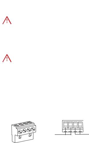
2.Locate the orange power connector.
Power Connector |
Power Connector, Top |
+ - + -
+ -
Power Supply
Wiring
Terminals
Daisy Chain
to Device
Wiring
Terminals
(Optional Use)
Publication 1788-IN052D-EN-P - February 2007
14 ControlNet-to-DeviceNet Linking Device
3.Loosen the two left-most terminal screws of the power connector.
IMPORTANT |
Do not connect more than two wires to any terminal. |
|
|
4.Insert the bare power supply wire ends into the left-side terminals of the power supply connector using the diagram as a guide.
5.Tighten the two left terminal screws using 0.6 Nm (7 in-lb) torque.
IMPORTANT
The power supply connector must be inserted into the CN2DN device for power to reach any devices daisy chained from the CN2DN power supply connector.
6.If you choose to connect another device to the power supply connector of the CN2DN device, loosen the two terminal screws on the right side of the connector.
7.Insert the bare device power wire ends into the two right terminals using the diagram as a reference.
8.Tighten the two right terminal screws using 0.6 Nm (7 in-lb) torque.
9.Insert the power supply connector into the power supply connector port.
10.Reapply power to the dc power supply.
The LED indicators on the right side of the CN2DN device will flash red to indicate power has been connected.
You have completed wiring the power supply to the CN2DN device.
Publication 1788-IN052D-EN-P - February 2007
ControlNet-to-DeviceNet Linking Device 15
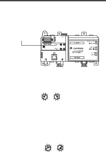
Set the Node Addresses and Communication Rate
Complete the following steps to set the node addresses using the switches on the front of the CN2DN device.
CN2DN Device Switches
DeviceNet
Address
Switches
|
|
|
|
|
|
|
|
|
|
|
|
|
|
|
|
|
|
|
|
ControlNet |
|||
|
|
Address |
|||
DeviceNet Baud |
Switches |
||||
Rate Switch |
|
|
|
|
|
1.To set the DeviceNet node address, use a small flat-head screwdriver to turn the arrows of the switches towards the desired node numbers.
DeviceNet switches shown set to node 14.
2 |
4 |
2 |
4 |
||||||
|
|
|
|
|
|
|
|
|
|
|
0 |
|
|
|
0 |
|
|
||
8 |
6 |
8 |
6 |
||||||
|
|
|
MSD |
|
|
|
LSD |
||
2.To set the DeviceNet communication rate, turn the DeviceNet baud rate switch to the communication rate your DeviceNet network is configured to, for example 125 K, 250 K, or 500 K.
3.To set the ControlNet node address, use a small Phillips-head screwdriver to turn the arrows of the switches towards the desired node numbers.
ControlNet switches shown set to node 26.
2 |
4 |
2 |
4 |
||||||
|
|
|
|
|
|
|
|
|
|
|
0 |
|
|
|
0 |
|
|
||
PGM |
6 |
8 |
6 |
||||||
|
|
MSD |
|
|
|
|
|
LSD |
|
You have completed setting the ControlNet and DeviceNet node addresses and communication rate.
Publication 1788-IN052D-EN-P - February 2007
16 ControlNet-to-DeviceNet Linking Device
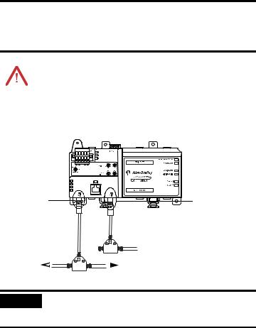
Connect the CN2DN Device to a ControlNet Network
Complete the following steps to connect your CN2DN linking device to the ControlNet network.
WARNING |
If you connect or disconnect the communications cable with power |
||
|
|
|
applied to this module or any device on the network, an electrical arc |
|
|
|
can occur. This could cause an explosion in hazardous location |
|
|
|
installations. |
|
|
|
|
1.Attach the BNC connector of the ControlNet cable to ControlNet port A.
Attach the BNC Connector of the ControlNet tap to ControlNet port A.
If using redundant cabling, attach the BNC connector of the ControlNet tap to ControlNet port B.
Redundant ControlNet
 Network Cable (Optional)
Main ControlNet
Network Cable 
 Main ControlNet
Network Cable
IMPORTANT
Do not connect more than one ControlNet network to the CN2DN device at a time. Connecting the CN2DN device to two networks at one time will cause erratic behavior of the CN2DN device.
2.If you are connecting to redundant media, attach the BNC connector of the other ControlNet cable to ControlNet port B.
The CN2DN linking device is now connected to the ControlNet network.
Publication 1788-IN052D-EN-P - February 2007
Loading...