


 Loading...
User Manual
EtherNet/IP to DeviceNet Linking Device
Catalog Number 1788-EN2DNR
Important User Information
Read this document and the documents listed in the additional resources section about installation, configuration, and operation of this equipment before you install, configure, operate, or maintain this product. Users are required to familiarize themselves with installation and wiring instructions in addition to requirements of all applicable codes, laws, and standards.
Activities including installation, adjustments, putting into service, use, assembly, disassembly, and maintenance are required to be carried out by suitably trained personnel in accordance with applicable code of practice.
If this equipment is used in a manner not specified by the manufacturer, the protection provided by the equipment may be impaired.
In no event will Rockwell Automation, Inc. be responsible or liable for indirect or consequential damages resulting from the use or application of this equipment.
The examples and diagrams in this manual are included solely for illustrative purposes. Because of the many variables and requirements associated with any particular installation, Rockwell Automation, Inc. cannot assume responsibility or liability for actual use based on the examples and diagrams.
No patent liability is assumed by Rockwell Automation, Inc. with respect to use of information, circuits, equipment, or software described in this manual.
Reproduction of the contents of this manual, in whole or in part, without written permission of Rockwell Automation, Inc., is prohibited.
Throughout this manual, when necessary, we use notes to make you aware of safety considerations.
WARNING: Identifies information about practices or circumstances that can cause an explosion in a hazardous environment, which may lead to personal injury or death, property damage, or economic loss.
ATTENTION: Identifies information about practices or circumstances that can lead to personal injury or death, property damage, or economic loss. Attentions help you identify a hazard, avoid a hazard, and recognize the consequence.
IMPORTANT Identifies information that is critical for successful application and understanding of the product.
Labels may also be on or inside the equipment to provide specific precautions.
SHOCK HAZARD: Labels may be on or inside the equipment, for example, a drive or motor, to alert people that dangerous voltage may be present.
BURN HAZARD: Labels may be on or inside the equipment, for example, a drive or motor, to alert people that surfaces may reach dangerous temperatures.
ARC FLASH HAZARD: Labels may be on or inside the equipment, for example, a motor control center, to alert people to potential Arc Flash. Arc Flash will cause severe injury or death. Wear proper Personal Protective Equipment (PPE). Follow ALL Regulatory requirements for safe work practices and for Personal Protective Equipment (PPE).
Allen-Bradley, Rockwell Software, Studio 5000, Studio 5000 Logix Designer, RSNetWorx, RSLinx, and Rockwell Automation are trademarks of Rockwell Automation, Inc. Trademarks not belonging to Rockwell Automation are property of their respective companies.

|
Table of Contents |
|
Preface |
Additional Resources . . . . . . . . . . . . . . . . . . . . . . . . . . . . . . . . . . . . . . . . . . . . . . |
. 5 |
|
Chapter 1 |
|
Linking Device Overview |
About the Linking Device . . . . . . . . . . . . . . . . . . . . . . . . . . . . . . . . . . . . . . . . . |
. 7 |
|
Features . . . . . . . . . . . . . . . . . . . . . . . . . . . . . . . . . . . . . . . . . . . . . . . . . . . . . . . . . . |
. 8 |
|
Linking Device Features . . . . . . . . . . . . . . . . . . . . . . . . . . . . . . . . . . . . . . . |
. 8 |
|
EtherNet/IP Features. . . . . . . . . . . . . . . . . . . . . . . . . . . . . . . . . . . . . . . . . . |
. 8 |
|
DeviceNet Features. . . . . . . . . . . . . . . . . . . . . . . . . . . . . . . . . . . . . . . . . . . . |
. 8 |
|
DeviceNet Standard and Safety I/O . . . . . . . . . . . . . . . . . . . . . . . . . . . . . . . . |
. 8 |
|
Add I/O Online (Online Scanlist Changes Allowed in Run Mode). . . . |
. 8 |
|
Chapter 2 |
|
Install the Linking Device |
System Requirements. . . . . . . . . . . . . . . . . . . . . . . . . . . . . . . . . . . . . . . . . . . . . . |
. 9 |
|
Required Hardware. . . . . . . . . . . . . . . . . . . . . . . . . . . . . . . . . . . . . . . . . . . . |
. 9 |
|
Required Software. . . . . . . . . . . . . . . . . . . . . . . . . . . . . . . . . . . . . . . . . . . . . |
. 9 |
|
Connect the Linking Device to the EtherNet/IP Network. . . . . . . . . . . |
10 |
|
Connect the Linking Device to the DeviceNet Network. . . . . . . . . . . . . |
10 |
|
Set the DeviceNet Node Address and Data Rate . . . . . . . . . . . . . . . . . . . . |
11 |
|
Set the DeviceNet Node Address and Data Rate by Using the |
|
|
Rotary Switches . . . . . . . . . . . . . . . . . . . . . . . . . . . . . . . . . . . . . . . . . . . . . . |
11 |
|
Set the DeviceNet Node Address and Data Rate |
|
|
by Using RSNetWorx for DeviceNet Software. . . . . . . . . . . . . . . . . . |
12 |
|
Set the Linking Device IP Address . . . . . . . . . . . . . . . . . . . . . . . . . . . . . . . . . |
12 |
|
Set the Linking Device IP Address by Using the Rotary Switches . 12 |
|
|
Set the Linking Device IP Address by Using DHCP/BOOTP . . . |
13 |
|
Set the Linking Device IP Address by Using RSLinx Software . . . . |
15 |
|
Set the Linking Device IP Address by Using the Linking Device |
|
|
Web Pages . . . . . . . . . . . . . . . . . . . . . . . . . . . . . . . . . . . . . . . . . . . . . . . . . . . |
16 |
|
Configure the Driver in RSLinx Software . . . . . . . . . . . . . . . . . . . . . . . . . . |
18 |
|
Register the EDS File . . . . . . . . . . . . . . . . . . . . . . . . . . . . . . . . . . . . . . . . . . . . . |
18 |
|
Chapter 3 |
|
Configure the Linking Device |
RSNetWorx for DeviceNet Software . . . . . . . . . . . . . . . . . . . . . . . . . . . . . . |
19 |
|
Set the DeviceNet Node Address and Data Rate . . . . . . . . . . . . . . . . |
20 |
|
Enable/Disable Autobaud. . . . . . . . . . . . . . . . . . . . . . . . . . . . . . . . . . . . . |
23 |
|
Configure DeviceNet I/O . . . . . . . . . . . . . . . . . . . . . . . . . . . . . . . . . . . . |
25 |
|
Studio 5000 Environment . . . . . . . . . . . . . . . . . . . . . . . . . . . . . . . . . . . . . . . . |
28 |
|
Add the Linking Device to a Logix Designer Application . . . . . . . . |
28 |
|
Configure the Linking Device . . . . . . . . . . . . . . . . . . . . . . . . . . . . . . . . . |
28 |
|
Assembly Objects and Connections . . . . . . . . . . . . . . . . . . . . . . . . . . . . |
31 |
Rockwell Automation Publication 1788-UM059A-EN-P - August 2014 |
3 |

Table of Contents |
|
|
|
Chapter 4 |
|
USB Cable |
Connect via USB to the Linking Device . . . . . . . . . . . . . . . . . . . . . . . . . . . . |
33 |
|
Configure the USB Driver. . . . . . . . . . . . . . . . . . . . . . . . . . . . . . . . . . . . . |
34 |
|
Chapter 5 |
|
SD Card |
Install or Remove the SD Card . . . . . . . . . . . . . . . . . . . . . . . . . . . . . . . . . . . . |
37 |
|
Load or Store to the SD Card. . . . . . . . . . . . . . . . . . . . . . . . . . . . . . . . . . . . . . |
38 |
|
Store to the SD Card. . . . . . . . . . . . . . . . . . . . . . . . . . . . . . . . . . . . . . . . . . |
38 |
|
Load from the SD Card . . . . . . . . . . . . . . . . . . . . . . . . . . . . . . . . . . . . . . . |
39 |
|
Chapter 6 |
|
Diagnostic Web Pages |
Diagnostic Web Pages—DeviceNet . . . . . . . . . . . . . . . . . . . . . . . . . . . . . . . . |
41 |
|
DeviceNet Status . . . . . . . . . . . . . . . . . . . . . . . . . . . . . . . . . . . . . . . . . . . . . |
41 |
|
Active Nodes . . . . . . . . . . . . . . . . . . . . . . . . . . . . . . . . . . . . . . . . . . . . . . . . . |
41 |
|
Idle Nodes . . . . . . . . . . . . . . . . . . . . . . . . . . . . . . . . . . . . . . . . . . . . . . . . . . . |
41 |
|
Faulted Nodes. . . . . . . . . . . . . . . . . . . . . . . . . . . . . . . . . . . . . . . . . . . . . . . . |
41 |
|
Invalid Nodes . . . . . . . . . . . . . . . . . . . . . . . . . . . . . . . . . . . . . . . . . . . . . . . . |
42 |
|
Node Status . . . . . . . . . . . . . . . . . . . . . . . . . . . . . . . . . . . . . . . . . . . . . . . . . . |
42 |
|
Diagnostic Web Pages—Ethernet. . . . . . . . . . . . . . . . . . . . . . . . . . . . . . . . . . |
44 |
|
Diagnostic Overview. . . . . . . . . . . . . . . . . . . . . . . . . . . . . . . . . . . . . . . . . . |
44 |
|
Network Settings . . . . . . . . . . . . . . . . . . . . . . . . . . . . . . . . . . . . . . . . . . . . . |
44 |
|
Ethernet Statistics . . . . . . . . . . . . . . . . . . . . . . . . . . . . . . . . . . . . . . . . . . . . |
44 |
|
Ring Statistics . . . . . . . . . . . . . . . . . . . . . . . . . . . . . . . . . . . . . . . . . . . . . . . . |
45 |
|
Diagnostic Web Pages—Miscellaneous. . . . . . . . . . . . . . . . . . . . . . . . . . . . . |
45 |
|
Crash Display . . . . . . . . . . . . . . . . . . . . . . . . . . . . . . . . . . . . . . . . . . . . . . . . |
45 |
|
Heap Statistics . . . . . . . . . . . . . . . . . . . . . . . . . . . . . . . . . . . . . . . . . . . . . . . |
45 |
|
Appendix A |
|
Status Indicators |
Linking Device . . . . . . . . . . . . . . . . . . . . . . . . . . . . . . . . . . . . . . . . . . . . . . . . . . . |
47 |
|
EtherNet/IP Network . . . . . . . . . . . . . . . . . . . . . . . . . . . . . . . . . . . . . . . . . . . . |
47 |
|
DeviceNet Network . . . . . . . . . . . . . . . . . . . . . . . . . . . . . . . . . . . . . . . . . . . . . . |
47 |
Index |
|
|
4 |
Rockwell Automation Publication 1788-UM059A-EN-P - August 2014 |

Preface
Additional Resources
These documents contain additional information concerning related products from Rockwell Automation.
Resource |
Description |
|
|
Industrial Automation Wiring and Grounding Guidelines, |
Provides general guidelines for installing a Rockwell |
publication 1770-4.1 |
Automation industrial system. |
|
|
DeviceNet Media Design and Installation Guide, |
Provides information about how to design, install and |
publication DNET-UM072 |
troubleshoot a DeviceNet cable system. |
|
|
DeviceNet Network Configuration User Manual, |
Describes how to use DeviceNet modules with your |
publication DNET-UM004 |
Logix5000 controller and communicate with various |
|
devices on the DeviceNet network. |
|
|
DeviceNet Modules Installation Instructions, |
Describes how to install and start DeviceNet module |
publication DNET-IN001 |
systems with Logix5000 controllers. |
|
|
EtherNet/IP Embedded Switch Technology Application |
Describes how to install, configure and maintain linear |
Guide, publication ENET-AP005 |
and device level ring (DLR) networks that use Rockwell |
|
Automation EtherNet/IP devices with embedded switch |
|
technology. |
|
|
Product Certifications website, http://www.ab.com |
Provides declarations of conformity, certificates, and other |
|
certification details. |
|
|
You can view or download publications at http:/www.rockwellautomation.com/literature/. To order paper copies of technical documentation, contact your local Allen-Bradley distributor or Rockwell Automation sales representative.
Rockwell Automation Publication 1788-UM059A-EN-P - August 2014 |
5 |

Preface
Notes:
6 |
Rockwell Automation Publication 1788-UM059A-EN-P - August 2014 |

Chapter 1
Linking Device Overview
About the Linking Device
The 1788-EN2DNR EtherNet/IP-to-DeviceNet linking device lets you seamlessly connect your information or control-level networks with your device-level network.
The linking device provides full DeviceNet master functionality, so you can connect up to 63 DeviceNet slave devices to an Ethernet TCP/IP interface that supports the EtherNet/IP network and an HTTP web server. For example, you could use the linking device to do the following:
•As a gateway to connect information or control-level networks to devicelevel networks for programming, configuration, control, or data collection
•As a router/bridge to connect the EtherNet/IP network to the DeviceNet network
The linking device provides centralized data storage, or I/O tables, for data shared between the DeviceNet and EtherNet/IP networks. Data is placed into the I/O tables by one network interface, allowing the data to be read through the other network interface.
The linking device appears as a single device on either network by using standard protocol mechanisms. No special, or extended, protocol features are required for the devices on either network to read or write the data flowing through the I/O tables; all cross-network activity is transparent to the devices on either network.
The linking device also supports Device Level Ring (DLR) and CIP Safety connections.
Phoenix connectors are provided for power and DeviceNet connections. Two RJ45 style connectors are provided for EtherNet/IP connection.
The linking device can be mounted to a DIN rail.
Rockwell Automation Publication 1788-UM059A-EN-P - August 2014 |
7 |

Chapter 1 Linking Device Overview
Features The 1788-EN2DNR module has the following features.
Linking Device Features
For Class 0 CIP Safety connections, 5 ms maximum delay from network to network
EtherNet/IP Features
•The linking device supports these connections:
–32 Class 0 connections (Safety)
–21 Class 1 connections (1 excl. owner, 20 input only/listen only)
–16 Class 3 connections
•Integrated web server
•Beacon-based DLR (Device Level Ring) support
DeviceNet Features
•63 nodes on the DeviceNet network
•Master/scanner as well as slave/adapter functionality
•Safety I/O
•Scanner configuration using RSNetWorx™ for DeviceNet software
•Autoscan
•ADR (Automatic Device Replacement) with a capacity of 256 kB
•Quick connect (as originator)
•I/O slave messaging (bit strobe, polling, cyclic, change of state)
DeviceNet Standard and
Safety I/O
Add I/O Online (Online
Scanlist Changes Allowed in
Run Mode)
The 1788-EN2DNR linking device features the possibility to bridge CIP safety messages. It supports 32 CIP safety connections, with a maximum internal delay of 5 ms.
The Online Scanlist Changes Allowed in Run (OSCAR) feature lets you manipulate the DeviceNet scanner configuration while the scanner is in Run mode. Configuration items that can be changed in Run mode include the scanlist, ADR, and ISD (InterScan Delay). Safety I/O cannot be added to the scanlist.
8 |
Rockwell Automation Publication 1788-UM059A-EN-P - August 2014 |

Chapter 2
Install the Linking Device
System Requirements
The following hardware and software components are required to use the linking device.
Required Hardware
•1788-EN2DNR linking device
•Two 121 Ω (1%, 1/4 watt) termination resistors (shipped with the linking device)
•DeviceNet cabling, power, and devices forming a DeviceNet network
•Ethernet cabling
•Computer with USB connection or access to the Ethernet network
•24 V DC power to the linking device
DeviceNet power can be used; however, using DeviceNet power bypasses the DeviceNet network isolation.
Required Software
•RSNetWorx for DeviceNet software, version 21 or later, to configure DeviceNet devices and the linking device’s DeviceNet functionality
•RSLinx® software, version 3.51 or later
•RSLogix 5000 version 20 or Studio 5000 Automation Engineering & Design Environment™, version 21 or later.
Rockwell Automation Publication 1788-UM059A-EN-P - August 2014 |
9 |

Chapter 2 Install the Linking Device
Connect the Linking Device to the EtherNet/IP Network
Connect the EtherNet/IP network cable to either of the two RJ45 ports on the front of the linking device.
RJ45 Ports
Connect the Linking Device to the DeviceNet Network
ATTENTION: Do not wire more than two conductors on any single terminal. To comply with the CE Low Voltage Directive (LVD), this equipment must be powered from a source compliant with safety extra low voltage (SELV) or protected extra low voltage (PELV). To comply with UL restrictions, this equipment must be powered from a source compliant with Class 2 or Limited Voltage/Current.
1.With power to the linking device off, connect the DeviceNet network cable to the DeviceNet connector on the linking device.
The female terminal block connector is provided with the linking device.
|
|
|
|
|
|
(Red) Net Power 24V DC |
|
|
|
|
|
|
|
|
|
|
|
|
|
|
|
|
|
|
|
|
(White) CAN High + |
|
|
|
|
|
|
CAN Shield |
|
|
|
|
|
|
|
|
|
|
|
|
|
(Blue) CAN Low |
|
|
|
|
|
|
|
|
|
|
|
|
|
(Black) Net Power 24V DC Common 31442-M |
|
|
|
|
|
|
|
TIP |
|
|
The two 121 ? termination resistors that come with the linking device are |
|||
|
|
|
required for proper network termination at each end of the trunk line. See the |
|||
DeviceNet Specification (available from the Open DeviceNet Vendors Association at http://www.odva.org) for specific rules on DeviceNet connections and termination.
10 |
Rockwell Automation Publication 1788-UM059A-EN-P - August 2014 |
Install the Linking Device |
Chapter 2 |
|
|
Set the DeviceNet Node
Address and Data Rate
2.Connect the power cable to the linking device.
The female terminal block connector is provided with the linking device.
1 |
2 |
3 |
Pin No. |
Description |
|
|
1 |
+24 V DC |
|
|
2 |
GND |
|
|
3 |
PE (Protective Earth) |
|
|
3. Apply power to the linking device and DeviceNet network.
Two methods can be used to set the DeviceNet node address and the data rate:
•Use the node address and data rate rotary switches on the side of the linking device
•Use RSNetWorx for DeviceNet software
Set the DeviceNet Node Address and Data Rate by Using the Rotary Switches
The rotary switches are on the right side of the linking device.


 NA x10


 NA x1
NA x1
DATA RATE
Set the desired node address and data rate according to the table below.
Switch |
Node Address |
|
|
00 - 63 |
DeviceNet node address |
|
|
Other value |
Node address selected via RSNetWorx |
|
software |
|
|
Switch |
Data Rate |
|
|
0 |
125 kbps |
|
|
Rockwell Automation Publication 1788-UM059A-EN-P - August 2014 |
11 |

Chapter 2 Install the Linking Device
Switch |
Data Rate |
|
|
1 |
250 kbps |
|
|
2 |
500 kbps |
|
|
Other value |
Data rate selected via RSNetWorx |
|
software |
|
|
Set the Linking Device
IP Address
Set the DeviceNet Node Address and Data Rate by Using RSNetWorx for DeviceNet Software
See Set the DeviceNet Node Address and Data Rate on page 20 for information about using RSNetWorx software to set node address and data rate.
Four methods can be used to set the linking device IP address:
•Use the IP address rotary switches on the side of the linking device
•Use the DHCP protocol
•Use RSLinx Software
•Use the web pages of the linking device
Set the Linking Device IP Address by Using the Rotary Switches
The rotary switches are on the right side of the linking device.
x100
x10
x1
Set the IP address according to the table below.
Switch |
IP Address |
000Administrative mode
The linking device uses the IP address that was used last startup The web pages are available
001 - 254 |
192.168.1.XYZ where XYZ is the value of the three switches |
|
|
888 |
Reset the linking device to initial out-of-box settings |
|
|
Other value |
The linking device starts in operating mode, using the latest configured IP |
|
address |
12 |
Rockwell Automation Publication 1788-UM059A-EN-P - August 2014 |

|
Install the Linking Device Chapter 2 |
|
|
Set the Linking Device IP Address by Using DHCP/BOOTP |
|
TIP |
The use of DHCP is the default configuration for the linking device as shipped. |
When DHCP/BOOTP is enabled and a DHCP or BOOTP server is found, the
IP address, subnet mask, and gateway address are automatically configured by the
DHCP server, as shown in the following figure.
Automatic Configuration
Launch a DHCP/BOOTP Server. If using the Rockwell Automation DHCP/ BOOTP server, then follow these steps to change the IP address, Subnet mask, and Gateway address from this dialog box.
1.Click New.
The Properties dialog box appears.
2.Enter the appropriate values into the following boxes.
•Ethernet address (MAC ID) from the linking device product ID label
•IP address
•Subnet Mask
•Gateway (IP address)
3.Click OK.
Rockwell Automation Publication 1788-UM059A-EN-P - August 2014 |
13 |

Chapter 2 Install the Linking Device
The following figure shows a flowchart describing how the IP configuration is determined when the linking device is powered up.
IP Configuration Flowchart
Start
No |
Rotary |
Yes |
|
Switches = 888? |
|
|
|
|
|
|
|
|
|
|
Factory Reset to DHCP
Rotary
Switches = 000?
Yes |
|
|
No |
||
|
|
|
|
|
LED Indication |
|
|
|
|
|
|
Admin Mode |
|
Operational Mode |
|
||
|
|
|
|
|
|
|
|
|
|
|
|
|
|
No |
Rotary |
Yes |
||
|
|
Switches |
||||
|
|
|
|
|
|
|
|
|
|
1 - 254? |
|
|
|
|
|
|
|
|
|
|
|
|
|
|
|
|
|
Fetch Stored Settings |
|
|
IP Address: |
|||
|
|
192.168.1.X |
||||
|
|
|
|
|
||
DHCP |
Yes |
|
|
|
|||
Enabled? |
|
|
|
|
|
|
|
|
|
|
|
|
|
||
|
|
|
|
|
|
|
|
|
|
|
|
|
|
|
|
|
|
|
Fetch IP Address |
|
|
|
|
|
|
|
|
|
|
||
No |
|
|
from Server |
|
|
|
|
|
|
|
|
|
|
|
|
|
|
|
|
|
|
|
|
|
|
|
|
|
|
|
|
|
|
|
|
|
|
|
|
IP Address:
Static Setting
Start up
TIP You can enable these values by using the linking device’s IP Configuration web page. Refer to Set the Linking Device IP Address by Using the Linking Device Web Pages on page 16.
14 |
Rockwell Automation Publication 1788-UM059A-EN-P - August 2014 |

Install the Linking Device |
Chapter 2 |
|
|
Set the Linking Device IP Address by Using RSLinx Software
To use RSLinx software to set the IP address of the linking device, follow these steps.
1.Connect to the linking device using a USB cable.
2.From the Communications menu, choose RSWho.
3.Navigate to the USB port.
4.Right-click the linking device and choose Module Configuration.
5.Click the Port Configuration tab.
6.For Network Configuration Type, click Static to permanently assign this configuration to the port.
7.Type the desired information in the appropriate boxes.
Rockwell Automation Publication 1788-UM059A-EN-P - August 2014 |
15 |
Chapter 2 Install the Linking Device
8. Configure the port settings.
To |
Then |
|
|
|
|
Use the default port speed and duplex |
Leave Auto-negotiate port speed and duplex checked. |
|
settings |
This setting determines the actual speed and duplex setting. |
|
|
|
|
Manually configure your port’s speed |
Follow these steps. |
|
and duplex settings |
1. |
Clear the Auto-negotiate port speed and duplex checkbox. |
|
2. |
From the Current Port Speed pull-down menu, choose a port |
|
|
speed. |
|
3. |
From the Current Duplex pull-down menu, choose the |
|
|
appropriate Duplex value. |
|
|
|
|
|
|
IMPORTANT Consider the following when you configure the linking device’s port settings:
• If the linking device is connected to an unmanaged switch, leave Auto-negotiate port speed and duplex checked or the communications to the linking device fails.
• If you are forcing the port speed and duplex with a managed switch, the corresponding port of the managed switch must be forced to the same settings or the linking device fails.
9. Click OK.
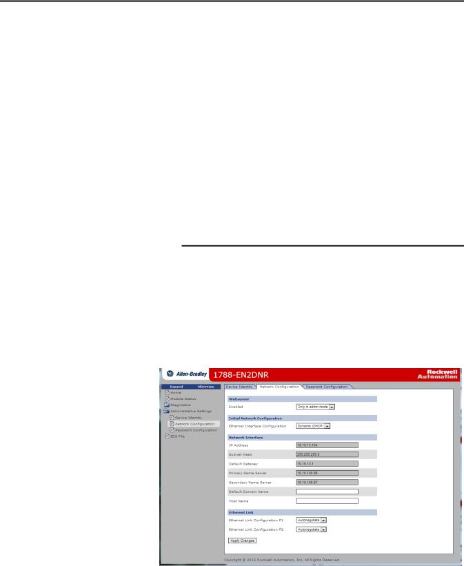
Set the Linking Device IP Address by Using the Linking Device
Web Pages
The EtherNet/IP address can also be configured by using the Network
Configuration web page on the linking device, as shown in the following figure.
16 |
Rockwell Automation Publication 1788-UM059A-EN-P - August 2014 |
Loading...