


1794-IE8H
Table of contents
 Loading...
Installation Instructions
FLEX I/O 8 Input HART Analog Module
Catalog Number 1794-IE8H, Series B
Topic Page
Important User Information 2
Environment and Enclosure 3
Prevent Electrostatic Discharge 4
North American Hazardous Location Approval 5
European Hazardous Location Approval 6
About the Module 7
Install the Module 7
Wire the Module 9
Ground the Module 11
Input Map 12
Configuration Map 13
Cyclic HART Input Data 17
Input Map (Series A Mode) 23
Configuration Map (Series A Mode) 24
Extended Configuration Data Table (Series A Mode) 26
Field Descriptions 27
Status Indicators 31
Specifications 32
2 FLEX I/O 8 Input HART Analog Module
WARNING
IMPORTANT
ATTENTION
SHOCK HAZARD
BURN HAZARD
Important User Information
Solid state equipment has operational characteristics differing from those of electromechanical
equipment. Safety Guidelines for the Application, Installation and Maintenance of Solid State Controls
(Publication SGI-1.1 available from your local Rockwell Automation sales office or online at
http://literature.rockwellautomation.com
equipment and hard-wired electromechanical devices. Because of this difference, and also because of the
wide variety of uses for solid state equipment, all persons responsible for applying this equipment must
satisfy themselves that each intended application of this equipment is acceptable.
In no event will Rockwell Automation, Inc. be responsible or liable for indirect or consequential damages
resulting from the use or application of this equipment.
The examples and diagrams in this manual are included solely for illustrative purposes. Because of the
many variables and requirements associated with any particular installation, Rockwell Automation, Inc.
cannot assume responsibility or liability for actual use based on the examples and diagrams.
No patent liability is assumed by Rockwell Automation, Inc. with respect to use of information, circuits,
equipment, or software described in this manual.
Reproduction of the contents of this manual, in whole or in part, without written permission of Rockwell
Automation, Inc., is prohibited.
Throughout this manual, when necessary, we use notes to make you aware of safety considerations.
Identifies information about practices or circumstances that can cause an explosion
in a hazardous environment, which may lead to personal injury or death, property
damage, or economic loss.
Identifies information that is critical for successful application and understanding of
the product.
Identifies information about practices or circumstances that can lead to personal
injury or death, property damage, or economic loss. Attentions help you identify a
hazard, avoid a hazard and recognize the consequences.
) describes some important differences between solid state
Publication
Labels may be on or inside the equipment (for example, drive or motor) to alert
people that dangerous voltage may be present.
Labels may be on or inside the equipment (for example, drive or motor) to alert
people that surfaces may reach dangerous temperatures.
1794-IN108D-EN-P - January 2014
Environment and Enclosure
ATTENTION
WARNING
This equipment is intended for use in a Pollution Degree 2 industrial
environment, in overvoltage Category II applications (as defined in IEC 60664-1),
at altitudes up to 2000 m (6562 ft) without derating.
This equipment is considered Group 1, Class A industrial equipment according
to IEC/CISPR 11. Without appropriate precautions, there may be difficulties with
electromagnetic compatibility in residential and other environments due to
conducted and radiated disturbances.
This equipment is supplied as open-type equipment. It must be mounted within
an enclosure that is suitably designed for those specific environmental
conditions that will be present and appropriately designed to prevent personal
injury resulting from accessibility to live parts. The enclosure must have suitable
flame-retardant properties to prevent or minimize the spread of flame,
complying with a flame spread rating of 5VA, V2, V1, V0 (or equivalent) if
non-metallic. The interior of the enclosure must be accessible only by the use of
a tool. Subsequent sections of this publication may contain additional
information regarding specific enclosure type ratings that are required to comply
with certain product safety certifications.
In addition to this publication, see:
• Industrial Automation Wiring and Grounding Guidelines, for additional
installation requirements, Allen-Bradley publication 1770-4.1
• NEMA Standards 250 and IEC 60529, as applicable, for explanations of
the degrees of protection provided by different types of enclosure.
FLEX I/O 8 Input HART Analog Module 3
.
If you insert or remove the module while backplane power is on, an electrical
arc can occur. This could cause an explosion in hazardous location installations.
Be sure that power is removed or the area is nonhazardous before proceeding.
Publication
1794-IN108D-EN-P - January 2014
4 FLEX I/O 8 Input HART Analog Module
ATTENTION
ATTENTION
ATTENTION
This product is grounded through the DIN rail to chassis ground. Use zinc plated
yellow-chromate steel DIN rail to assure proper grounding. The use of other DIN
rail materials (for example, aluminum or plastic) that can corrode, oxidize, or are
poor conductors, can result in improper or intermittent grounding. Secure DIN
rail to mounting surface approximately every 200 mm (7.8 in.) and use
end-anchors appropriately.
Prevent Electrostatic Discharge
This equipment is sensitive to electrostatic discharge, which can cause internal
damage and affect normal operation. Follow these guidelines when you handle
this equipment:
• Touch a grounded object to discharge potential static.
• Wear an approved grounding wriststrap.
• Do not touch connectors or pins on component boards.
• Do not touch circuit components inside the equipment.
• Use a static-safe workstation, if available.
• Store the equipment in appropriate static-safe packaging when not in
use.
To comply with the CE Low Voltage Directive (LVD), all connected I/O must be
powered from a source compliant with the following:
Safety Extra Low Voltage (SELV) or Protected Extra Low Voltage (PELV).
Publication
1794-IN108D-EN-P - January 2014
FLEX I/O 8 Input HART Analog Module 5
WARNING
AVERTISSEMENT
ATTENTION
ATTENTION
North American Hazardous Location Approval
The following information applies when
operating this equipment in hazardous
locations:
Products marked "CL I, DIV 2, GP A, B, C, D " are suitable
for use in Class I Division 2 Groups A, B, C, D, Hazardous
Locations and nonhazardous locations only. Each
product is supplied with markings on the rating
nameplate indicating the hazardous location
temperature code. When combining prod ucts within a
system, the most adverse temperature code (lowest "T"
number) may be used to help determine the o verall
temperature code of the system. Combinations of
equipment in your system are subject to investigation
by the local Authority Having Jurisdiction at the time of
installation.
EXPLOSION HAZARD -
• Do not disconnect equipment
unless power has been removed or
the area is known to be
nonhazardous.
• Do not disconnect connections to
this equipment unless power has
been removed or the area is known
to be nonhazardous. Secure any
external connections that mate to
this equipment by using screws,
sliding latches, threaded
connectors, or other means
provided with this product.
• Substitution of components may
impair suitability for Class I,
Division 2.
• If this product contains batteries,
they must only be changed in an
area known to be nonhazardous.
Informations sur l’utilisation de cet équipement
en environnements dangereux:
Les produits marqués “CL I, DIV 2, GP A, B, C, D” ne
conviennent qu’à une utilisation en environnements de Cla sse I
Division 2 Groupes A, B, C, D dangereux et non d angereux.
Chaque produit est livré avec des marquages sur sa plaqu e
d’identification qui indiquent le code de tem pérature pour les
environnements dangereux. Lorsque plusieu rs produits sont
combinés dans un système, le code de température le plus
défavorable (code de température le plus faible ) peut être
utilisé pour déterminer le code de température global du
système. Les combinaisons d’équipements dans le système
sont sujettes à inspection par les autorités locales qualifiées
au moment de l’installation.
RISQUE D’EXPLOSION –
• Couper le courant ou s’assurer que
l’environnement est classé non
dangereux avant de débrancher
l'équipement.
• Couper le courant ou s'assurer que
l’environnement est classé non
dangereux avant de débrancher les
connecteurs. Fixer tous les
connecteurs externes reliés à cet
équipement à l'aide de vis, loquets
coulissants, connecteurs filetés ou
autres moyens fournis avec ce
produit.
• La substitution de composants
peut rendre cet équipement
inadapté à une utilisation en
environnement de Classe 1,
Division 2.
• S’assurer que l’environnement est
classé non dangereux avant de
changer les piles.
For Class I Division 2 applications, use only Class I Division 2 Listed or
Recognized accessories and modules approved for use within 1794 platform.
Do not remove or replace a Terminal Base unit while power is applied.
Interruption of the backplane can result in unintentional operation or machine
motion.
Publication
1794-IN108D-EN-P - January 2014
6 FLEX I/O 8 Input HART Analog Module
ATTENTION
WARNING
European Hazardous Location Approval
European Zone 2 Certification (The following applies when the product bears the Ex
or EEx Marking.)
This equipment is intended for use in potentially explosive atmospheres as defined by
European Union Directive 94/9/EC and has been found to comply with the Essential Health
and Safety Requirements relating to the design and construction of Category 3 equipment
intended for use in potentially explosive atmospheres, given in Annex II to this Directive.
Compliance with the Essential Health and Safety Requirements has been assured by
compliance with EN 60079-15 and EN 60079-0.
This equipment is not resistant to sunlight or other sources of UV radiation.
• This equipment must be installed in an enclosure providing at least IP54
protection when applied in Zone 2 environments.
• This equipment shall be used within its specified ratings defined by
Allen-Bradley.
• Provision shall be made to prevent the rated voltage from being
exceeded by transient disturbances of more than 40% when applied in
Zone 2 environments.
• This equipment must be used only with ATEX certified backplanes.
• Secure any external connections that mate to this equipment by using
screws, sliding latches, threaded connectors, or other means provided
with this product.
• Do not disconnect equipment unless power has been removed or the
area is known to be nonhazardous.
Publication
1794-IN108D-EN-P - January 2014
FLEX I/O 8 Input HART Analog Module 7
ATTENTION
40231
3
4
7
1
2
6
5
8
Label here or under here
About the Module
The HART analog modules can be used with ControlNet, Ethernet and
Profibus-DP (1794-APBDV1 only) adapters. When using the Series B module
with a Series B profile, you must have a ControlNet adapter Revision 5.1 or
higher or an Ethernet adapater Revision 4.2 or higher.
For this scenario (Series A profile with a Series B Module), the data maps
(input, configuration and extended configuration) are designated as Series A
Mode. Note, all other data maps are for a Series B module with a Series B
profile.
Only use the series A configuration when replacing a series A module with a
series B module. If you access the Series A configuration while using the
module as a series B unpredictably operation of the module may occur.
Install the Module
Read this for information about how to install the module. The module must
be used with a 1794-TB3G or 1794-TB3GS terminal base unit.
During mounting of all devices, be sure that all debris (such as metal chips or
wire strands) is kept from falling into the module. Debris that falls into the
module could cause damage on power up.
Publication
1794-IN108D-EN-P - January 2014
8 FLEX I/O 8 Input HART Analog Module
ATTENTION
IMPORTANT
IMPORTANT
IMPORTANT
41307
Do not remove or replace a Terminal Base unit while power is applied.
Interruption of the backplane can result in unintentional operation or machine
motion.
You must disable keying in your profile when replacing a series A module with
a series B module.
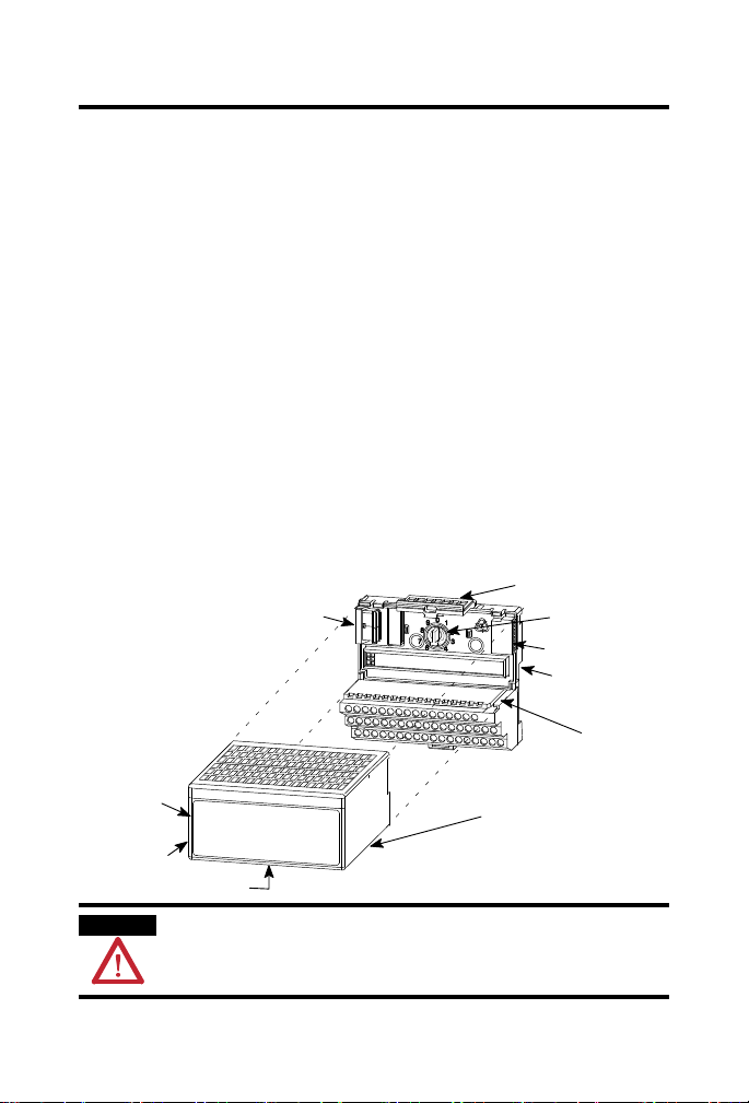
To install the module on a 1794 terminal base, refer to the figure and
complete the following.
1. Rotate the keyswitch (1) on the terminal base (2) clockwise to position
3 as required for this type of module.
Do not change the position of the keyswitch after wiring the terminal base
unit.
2. Make sure the flexbus connector (3) is pushed all the way to the left to
connect with the neighboring terminal base or adapter.
You cannot install the module unless the connector is fully extended.
3. Make sure the pins on the bottom of the module are straight so they
align properly with the connector in the terminal base.
4. Position the module (4) with its alignment bar (5) aligned with the
groove (6) on the terminal base.
5. Press firmly and evenly to seat the module in the terminal base unit,
noting that the module is seated when the latching mechanism (7) is
locked into the module.
6. Remove cap plug (8) and attach another terminal base unit to the right
of this terminal base unit if required.
Publication
1794-IN108D-EN-P - January 2014
FLEX I/O 8 Input HART Analog Module 9
WARNING
44861
Wire the Module
If you connect or disconnect wiring while the field-side power is on, an
electrical arc can occur. This could cause an explosion in hazardous location
installations. Be sure that power is removed or the area is nonhazardous before
proceeding.
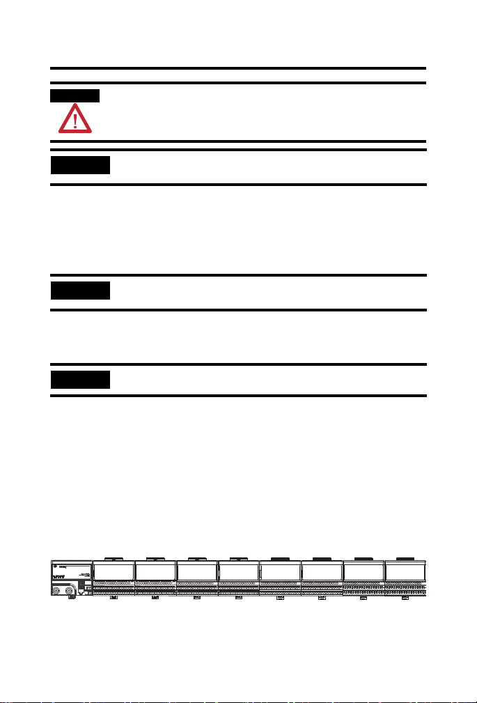
To connect two-wire transmitter devices for 1794-TB3G and 1794-TB3GS
bases, refer to the tables and figure and complete the following.
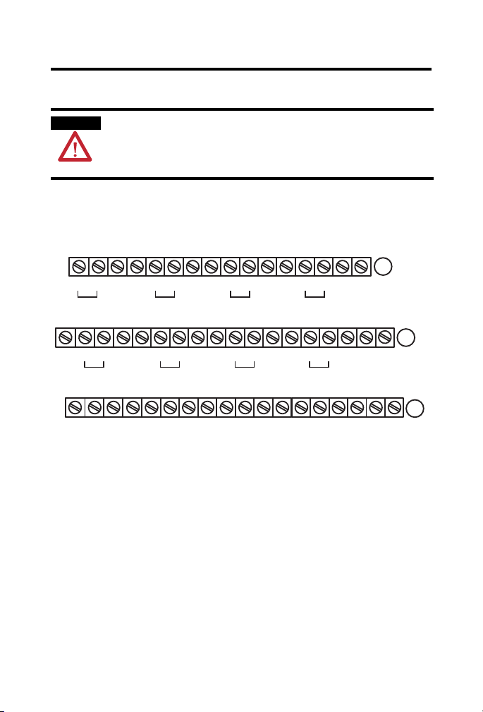
Module Wiring
0 1 2 3 4 5 6 7 8 9 10 11 12 13 14 15
A
+
sig sig
Ch0 Ch1 Ch3Ch2
17
18 19 20 21 22 23 24 25 26 27 28 29 30 31 32
16
+
sig
Ch4
35
36 37 38 39 40 41 42 43 44 45 46 47 48 49
34
+V COM
24V DC
Supply Out
+24V DC = Terminals C-34 and C-50
COM = C-35 and C-51
NC = No connection
For daisy-chaining : Supply in C-34 (+V) and C-35 (COM)
Supply out C-50 (+V) and C-51 (COM)
+
+
sig
Ch5
NC
+
sig
+
sig
33
B
+
sig
Ch6
+
sig
Ch7
50
51
NC
+V COM
24V DC
Supply Out
(1794-TB3G shown)
C
1. Connect the individual input wiring to (+) terminals (0, 4, 8, 12) on
the 0 to 15 row (A) and on the 16 to 33 row (B) (terminals 17, 21, 25,
29) as indicated in the table Wire Connections.
2. Connect the associated input to the corresponding (sig) terminal (1, 5,
9, 13) on the 0 to 15 row (A), and on the 16 to 33 row (B) (terminals
18, 22, 26, 30) for each input as indicated in the table Wire
Connections.
Publication
1794-IN108D-EN-P - January 2014
10 FLEX I/O 8 Input HART Analog Module
ATTENTION
ATTENTION
3. Refer to the Figure for other configurations.
4. Connect +V DC power to terminal 34 on the 34 to 51 row (C).
5. Connect -V to terminal 35 on the 34 to 51 row (C).
6. If continuing power to the next terminal base unit, connect a jumper
from terminal 50 (+V) on this base unit to terminal 34 on the next
base unit.
If continuing common to the next terminal base unit, connect a
jumper from terminal 51 (-V) on this base unit to terminal 35 on the
next base unit.
The 1794-IE8H module shall be used only with Listed Allen-Bradley (Rockwell
Automation) Power Supply (catalog number 1794-PS13) or Listed Class 2 source.
To reduce susceptibility to noise, power analog modules and digital modules
from separate power supplies.
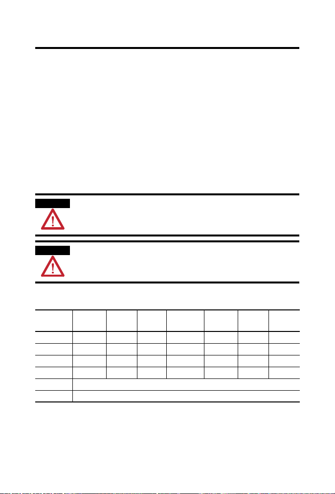
Wire Connections
Input Input
Source
Input 0 A-0 A-1 A-2 Input 4 B-17 B-18 B-19
Input 1 A-4 A-5 A-6 Input 5 B-21 B-22 B-23
Input 2 A-8 A-9 A-10 Input 6 B-25 B-26 B-27
Input 3 A-12 A-13 A-14 Input 7 B-29 B-30 B-31
+V Terminals 34 and 50
-V Terminals 35 and 51
Input
Signal
Input
Return
Input Input
Source
Input
Signal
Input
Return
Publication
1794-IN108D-EN-P - January 2014
FLEX I/O 8 Input HART Analog Module 11
IMPORTANT
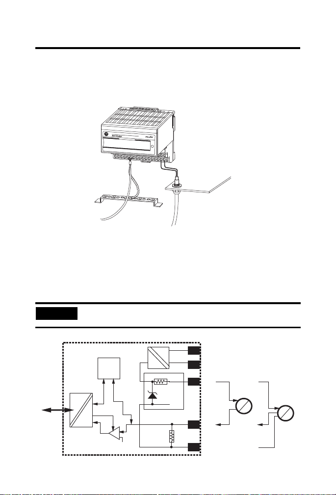
44862
43852
HART
Modem
1794-IE8H/B
Bus
uC
Flexbus
10 Ω
23.7 V
273 Ω
+V
-V
+
4...20 mA
sig
-
Xmit
4...20 mA
Xmit
I
P
I
P
Ground the Module
All I/O wiring must use shielded wire. Shields must be terminated external to
the module, such as bus bars and shield-terminating feed-throughs.
Inputs
Each input can be operated from an analog field device signal.
The channels in these modules are electrically connected to each other and
have a common plus-line.
When interconnecting several lines, you must consider the total accumulated
power.
Publication
1794-IN108D-EN-P - January 2014
Loading...